EP0874995B1 - Schaltungsanordnung und vorrichtung zur erfassung des drehverhaltens eines rades - Google Patents
Schaltungsanordnung und vorrichtung zur erfassung des drehverhaltens eines rades Download PDFInfo
- Publication number
- EP0874995B1 EP0874995B1 EP97919362A EP97919362A EP0874995B1 EP 0874995 B1 EP0874995 B1 EP 0874995B1 EP 97919362 A EP97919362 A EP 97919362A EP 97919362 A EP97919362 A EP 97919362A EP 0874995 B1 EP0874995 B1 EP 0874995B1
- Authority
- EP
- European Patent Office
- Prior art keywords
- pick
- measuring
- measuring data
- connection
- wheel
- Prior art date
- Legal status (The legal status is an assumption and is not a legal conclusion. Google has not performed a legal analysis and makes no representation as to the accuracy of the status listed.)
- Expired - Lifetime
Links
- 229910000831 Steel Inorganic materials 0.000 claims description 11
- 239000010959 steel Substances 0.000 claims description 11
- 239000004020 conductor Substances 0.000 claims description 4
- 230000008878 coupling Effects 0.000 claims description 3
- 238000010168 coupling process Methods 0.000 claims description 3
- 238000005859 coupling reaction Methods 0.000 claims description 3
- 238000011156 evaluation Methods 0.000 description 15
- 230000005291 magnetic effect Effects 0.000 description 4
- 239000002184 metal Substances 0.000 description 4
- 229910052751 metal Inorganic materials 0.000 description 4
- RYGMFSIKBFXOCR-UHFFFAOYSA-N Copper Chemical compound [Cu] RYGMFSIKBFXOCR-UHFFFAOYSA-N 0.000 description 3
- 229910000639 Spring steel Inorganic materials 0.000 description 3
- 230000008901 benefit Effects 0.000 description 3
- 238000001514 detection method Methods 0.000 description 3
- 230000000694 effects Effects 0.000 description 3
- 238000005259 measurement Methods 0.000 description 3
- 229910052802 copper Inorganic materials 0.000 description 2
- 239000010949 copper Substances 0.000 description 2
- 238000004519 manufacturing process Methods 0.000 description 2
- 230000008054 signal transmission Effects 0.000 description 2
- 230000028838 turning behavior Effects 0.000 description 2
- 229910001369 Brass Inorganic materials 0.000 description 1
- 230000005540 biological transmission Effects 0.000 description 1
- 239000010951 brass Substances 0.000 description 1
- 239000000969 carrier Substances 0.000 description 1
- 230000001419 dependent effect Effects 0.000 description 1
- 230000005684 electric field Effects 0.000 description 1
- 230000005294 ferromagnetic effect Effects 0.000 description 1
- 230000001939 inductive effect Effects 0.000 description 1
- 238000009413 insulation Methods 0.000 description 1
- 230000000149 penetrating effect Effects 0.000 description 1
- 229910000679 solder Inorganic materials 0.000 description 1
- 238000005476 soldering Methods 0.000 description 1
- 230000003068 static effect Effects 0.000 description 1
- XLYOFNOQVPJJNP-UHFFFAOYSA-N water Substances O XLYOFNOQVPJJNP-UHFFFAOYSA-N 0.000 description 1
- 238000003466 welding Methods 0.000 description 1
Images

Classifications
-
- B—PERFORMING OPERATIONS; TRANSPORTING
- B60—VEHICLES IN GENERAL
- B60T—VEHICLE BRAKE CONTROL SYSTEMS OR PARTS THEREOF; BRAKE CONTROL SYSTEMS OR PARTS THEREOF, IN GENERAL; ARRANGEMENT OF BRAKING ELEMENTS ON VEHICLES IN GENERAL; PORTABLE DEVICES FOR PREVENTING UNWANTED MOVEMENT OF VEHICLES; VEHICLE MODIFICATIONS TO FACILITATE COOLING OF BRAKES
- B60T8/00—Arrangements for adjusting wheel-braking force to meet varying vehicular or ground-surface conditions, e.g. limiting or varying distribution of braking force
- B60T8/17—Using electrical or electronic regulation means to control braking
- B60T8/171—Detecting parameters used in the regulation; Measuring values used in the regulation
-
- G—PHYSICS
- G01—MEASURING; TESTING
- G01P—MEASURING LINEAR OR ANGULAR SPEED, ACCELERATION, DECELERATION, OR SHOCK; INDICATING PRESENCE, ABSENCE, OR DIRECTION, OF MOVEMENT
- G01P3/00—Measuring linear or angular speed; Measuring differences of linear or angular speeds
- G01P3/42—Devices characterised by the use of electric or magnetic means
- G01P3/44—Devices characterised by the use of electric or magnetic means for measuring angular speed
- G01P3/48—Devices characterised by the use of electric or magnetic means for measuring angular speed by measuring frequency of generated current or voltage
- G01P3/481—Devices characterised by the use of electric or magnetic means for measuring angular speed by measuring frequency of generated current or voltage of pulse signals
Definitions
- the invention relates to a circuit arrangement for Detection of the turning behavior of a wheel as an input variable of a motor vehicle control system, with an active one Wheel sensor, which consists of a sensor in the form of a with the Wheel encoders and from a stationary Sensor consists of an active, a sensor element with permanent magnets as well as an electronic one Measuring element containing signal processing circuit has and via a connecting cable with an outside of Transducer arranged evaluation circuit connected is.
- a device with a circuit arrangement of this Type in which the sensor on one of electrical conductive material manufactured carrier body is attached, also belongs to the invention.
- Such circuit arrangements and devices for Detection of the speed of a vehicle wheel is already in various embodiments known and on the market.
- These wheel sensors or sensor systems that consist of one Rotary motion executing encoder or gear and from one Transducers exist, can basically be as train passive or active systems or sensors. So far were inductive for technological and price reasons Sensors, i.e. passive measuring systems, as wheel sensors for Motor vehicle control systems preferred. It's closed expect the importance of active sensors to increase.
- An active speed sensor is already from WO 95/17680 known. According to this document there is the measuring device basically from an encoder rotating with the wheel a magnetoresistive sensor element with an as Prestressing permanent magnets and from a Signal processing circuit integrated in one Circuit (IC) is housed. Via a 2-core Connection cables become the output signals of the active sensor routed to the central evaluation circuit.
- IC Signal processing circuit integrated in one Circuit
- a circuit arrangement for evaluating the output signal an active sensor is in DE 44 34 180 A1 shown.
- the sensor output signal is a binary one Current signal using a current mirror circuit is evaluated.
- the sensor is on the vehicle battery connected and is powered by the vehicle battery provided. Even with this circuit arrangement, everyone is individual wheel sensor with the controller or the common Evaluation circuit via an at least 2-core cable connected.
- the sensors pulse generators or Encoders that rotate with the wheel via magnetic, especially permanent magnetic fields.
- Known encoders contain permanent magnetic areas or areas that are in follow the direction of rotation with changing polarity. Basically, it is also possible to rotate the Sensor via light, radio frequency or electrical Fields that are modulated by the rotation, scan.
- Known active sensors provide one as the output signal impressed current, the current strength in the high / low cycle of the Measured value or pulse generator between a high value and changes at a low value.
- impressed current means here that the high and the low values each maintain their nominal values regardless of the Level of the operating voltage applied to the active sensor, e.g. the battery voltage, which is known to be in one Motor vehicle changes within relatively wide limits.
- the sensor element according to the aforementioned WO 95/17680 consists of an embodiment of a permanently magnetically biased, magnetoresistive Bridge element that with a complex Signal processing circuit to an assembly is summarized.
- the element is a bipolar, whose Power consumption between two fixed values over one ferromagnetic gear can be reversed.
- the invention is based on the general task Manufacturing expenditure for active sensors of this type without Limitation of electrical performance and to reduce mechanical resilience, namely Total effort of the completely assembled sensor, including wiring, connectors and assembly.
- the Special feature of the circuit arrangement according to the invention is that the measuring element has an active two-pole represents one as the output and measurement signal impressed current provides that the connection cable is a 1-wire Cable is and that the transducer on the Connection cable and a ground connection of the vehicle the evaluation circuit is connected.
- the Evaluation circuit is expediently via the Potential reference point of the control system with mass connected.
- the Transducer on an electrically conductive material existing support body is attached, is an electrical insulated connection cable available, from one pole of the as a two-pole measuring element to the connecting cable of the sensor leads, the connection cable is 1-wire and wherein the second connection of the dipole is galvanically connected the carrier body of the transmitter and via this with the Ground connection of the vehicle is connected.
- the restriction to a 1-core connection cable between the individual wheel sensors and the central one Evaluation circuit is inventively by working with embossed signal streams as information carriers between the measuring element and the evaluation circuit allows.
- One pole of the measuring element is over the 1-wire Cable connected to the evaluation circuit.
- the other pole lies on ground, the evaluation circuit on the Reference potential (GND) of the control system.
- GND Reference potential
- an active two-pole system is therefore used as the sensor used, the embossed currents of different heights in Transmission path. Distinguishing between two Signal current level is sufficient to transmit or evoke an alternating signal, the frequency of which changes the wheel turning behavior reproduces.
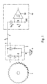
- a sensor 1 is shown in the form of a Toothed wheel; it could also be an encoder permanent magnetic areas that replace the teeth Trigger measurement signal pulses, or another known arrangement be used.
- the 1 serves as a symbolic sensor Measuring element 2 shown, which is preferably made of a Sensor element and one housed on an IC Signal processing circuit composed.
- the sensor element is, for example, a magnetoresistive one Bridge circuit with a bias permanent magnet suitable. This sensor element sits as close to the Periphery of the lock washer or the encoder 1.
- One Sensor element and the associated one Signal processing circuit becomes the measuring element 2 structurally united, which then according to its function and Mode of operation through the shown substitute image, namely by two current sources 3, 4 and a switch 5 is symbolized or represented symbolically.
- the two current sources 3 and 4 which cause the impressed currents I 1 and I 2 , are connected in parallel. Depending on the position of the switch 5, the total current that the sensor or measuring element 2 emits is either I 1 or I 1 + I 2 . Consequently, the output signal of the measuring element 2 consists of a current I A whose value changes between I 1 and I 1 + I 2 .
- the 1 is therefore an active one Sensor element consisting of a sensor element (e.g. a permanently magnetically biased, magnetoresistive Bridge circuit) and a signal processing circuit composed.
- the replacement picture is a circuit with two parallel power sources, only one of which is turned off can be.
- the active sensor element is a bipolar.
- a connection 6 of the two-pin connector (2) is connected via a 1-core cable 7 to an evaluation circuit 10, which can be part of the electronic controller of a motor vehicle control system (ABS, ASR, ASMS etc.).
- the second pole 8 of the two-pole (2) is connected directly to ground, for example by mechanical and galvanic coupling to the metal body 9 of a motor vehicle.
- the "quality" of the galvanic connection is not too high because, as already stated, a potential offset between the connection point or pole 8 of the two-pole or active sensor and the potential reference point GND of the evaluation circuit 10 has no effect. Neither static or direct current potential differences, nor the potential changes caused by so-called ring currents via ground loops and certain consumers are important, because these do not affect the level of the impressed current I 1 or I 1 + I 2 .
- a voltage source with the supply voltage or battery voltage U B and a flip-flop or signal amplifier circuit 10 ', the inputs of which are bridged by an ohmic resistor R, are symbolically represented as part of the evaluation circuit 8.
- the battery with the voltage U B causes a current I A flowing via the 1-wire cable 7, the measuring element 2, ground 9, the potential reference point GND and the input resistance R.
- U S symbolizes the signal voltage at the input of the circuit 10 ', which can be the input circuit of an ABS controller, for example.
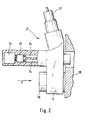
- An embodiment of an active sensor according to the Invention namely a transducer 2 'for FIG. 2 shows wheel speed detection on a motor vehicle.
- a plastic body are one from the actual one Sensor element 12 and the associated electronic Signal processing circuit 13 existing active Measuring element (12 + 13) and the electrical connections 14, 15, a component 16 for attaching the transducer 2 ' a carrier body 18 and a 1-core cable 17 or the Connection of this cable 17 to the active sensor (12 + 13) cast.
- the for mounting the sensor 2 ' serving component 16 exists in the present Embodiment from a thick-walled piece Brass tube.
- To attach the transducer 2 ' the consisting of electrically conductive material Carrier body 18 is one not shown in FIG.
- the component 16 is in the illustrated embodiment with the connecting wire 14 of the active measuring element or Signal processing circuit or the IC's 13 galvanic connected.
- the connection 15 leads via the cable 17 to the ABS controller input. It is enough just that Lead line 15 isolated because the second Terminal 14 of the active measuring element is at ground. In the Sensor 2 'penetrating water can electrical function of this active sensor is not affect because the contact 14 is electrically on the Ground potential of the motor vehicle is when the Connection to port 15 by complete overmolding is protected from moisture with plastic.
- a sensor of the type according to the invention can expediently also in the form of a so-called clip-on sensor be formed.
- This is a special form of a Snap connection or plug connection.
- Sensors are e.g. for scanning magnetized Bearing seals, which in this case serve as encoders, suitable.
- a retaining spring of the plug or snap device presses firmly into a corresponding notch on the body of the Transducer.
- the locking device is elastic trained and made of metal. It is stationary on the wheel bearing attached. Now the notch on the body of the Transducer also made of metal and with the connecting wire leading to earth (e.g. the Connection wire 14 in the embodiment according to FIG.
- Fig. 3 shows a schematic representation of the principle Structure of a measuring device with a steel wire as Connecting cable.
- the 1-core connection cable 20 has one Steel wire core 22 or steel wire core; so far you stopped the use of a cable with copper braid for required.
- the core 22 of the Cable 20 made of nickel-plated spring steel wire with a Diameter from about 0.8 to 1 mm.
- the measuring element 23 this Measuring sensor 19 is, as in the example according to FIG. 2, embedded in plastic.
- One end of the spring steel core 22 is also used as connector pin 24, which is in a receiving opening 25 of this end of the cable molded coupling or plug part 21 is located.
- the Steel wire is through in the plastic mass of the connector loop-like deflection 26 fixed.
- the steel wire 22 is molded with a hard plastic for insulation.
- the steel wire 22 is also through locked a loop-like deflection 28 and with the Measuring element 23 connected via a connecting bracket 29 in which one end of the steel wire 22 through a solder or weld 30 is fixed.
- Steel wire 22 and connection bracket 29 are through this soldering and welding point galvanically connected.
- the measurement signal is impressed with the help Signal currents are transmitted, the electrical is sufficient Conductivity of steel wire cores for signal transmission. It is possible to use spring steel wires with relatively thin Cable cross-section and high tensile strength, where the whip effects mentioned at the beginning are not occur.
- circuit arrangement according to the invention and the The measuring devices described are therefore characterized by particularly simple structure, high stability and simple Assembly off. These benefits are shared with the electrical properties achieved.
Landscapes
- Engineering & Computer Science (AREA)
- Transportation (AREA)
- Mechanical Engineering (AREA)
- Physics & Mathematics (AREA)
- General Physics & Mathematics (AREA)
- Transmission And Conversion Of Sensor Element Output (AREA)
Description
- Fig. 1
- in schematisch vereinfachter Darstellungsweise das Prinzip eines Ausführungsbeispiels der Schaltungsanordnung nach der Erfindung,
- Fig. 2
- in schematisch vereinfachter Darstellung eine Meßvorrichtung nach der Erfindung und
- Fig. 3
- in gleicher Darstellungsweise eine Meßvorrichtung gemäß einem weiteren Ausführungsbeispielder Erfindung.
Claims (5)
- Schaltungsanordnung zur Erfassung des Drehverhaltens eines Rades als Eingangsgröße eines Kraftfahrzeug-Regelungssystems, mit einem aktiven Radsensor (1,2,10), der aus einem Meßwertgeber in Form eines mit dem Rad umlaufenden Encoders (1) und aus einem ortsfesten Meßwertaufnehmer (2) besteht, der ein aktives, ein Sensorelement (5) mit Permanentmagneten und eine elektronische Signalverarbeitungsschaltung enthaltendes Meßelement (2) aufweist und über ein Anschlußkabel (7) mit einer außerhalb des Meßwertaufnehmers angeordneten Auswerteschaltung (10) verbunden ist, dadurch gekennzeichnet, daß das Meßelement(2,12+13) einen aktiven Zweipol darstellt, der als Ausgangs- und Meßsignal einen eingeprägten Strom (IA) liefert, daß das Anschlußkabel (7,17,27) als 1-adriges Kabel ausgebildet ist und daß der Meßwertaufnehmer (2) über das Anschlußkabel und über einen Masseanschluß (9) des Fahrzeugs an die Auswerteschaltung (10) angeschlossen ist.
- Schaltungsanordnung nach Anspruch 1, dadurch gekennzeichnet, daß als 1-adriges Kabel ein mechanisch stabiles Stahlkabel (27) vorgesehen ist.
- Vorrichtung zur Erfassung des Drehverhaltens eines Rades als Eingangsgröße eines Kraftfahrzeug-Regelungssystems, mit einem aktiven Radsensor (1,2,10), der aus einem Meßwertgeber in Form eines mit dem Rad umlaufenden Encoders (1) und aus einem ortsfesten Meßwertaufnehmer (2,2',19) besteht, der ein aktives Meßelement (12,13) aufweist, der an einem aus elektrisch leitendem Material gefertigten Trägerkörper (18) befestigt ist und über ein Anschlußkabel mit einer Auswerteschaltung verbunden ist, dadurch gekennzeichnet, daß der Meßwertaufnehmer (2',19) in einem Gehäuse ein als Zweipol ausgebildetes, einen eingeprägten Strom (IA) lieferndes Meßelement (12+13,23) und eine elektrisch isoliert geführte Anschlußleitung (15) enthält, die von einem Pol des Zweipols (12+13,23) zu dem Anschlußkabel (17,20) des Meßwertaufnehmers (2',19) führt, daß das Anschlußkabel (17,20) 1-adrig ist und daß der zweite Anschluß (14) des Zweipols (12+13,23) galvanisch mit dem Trägerkörper (18) des Meßwertaufnehmers (2',19) und über diesen mit einen Masseanschluß (9) des Kraftfahrzeugs verbunden ist.
- Vorrichtung nach Anspruch 3, dadurch gekennzeichnet, daß der Meßwertaufnehmer mit einem Befestigungselement (16) versehen ist, das an dem Trägerkörper (18) angeschraubt ist, wobei das Befestigungselement (16) mit dem zweiten Anschluß (14) des Zweipols (12+13) und mit dem Trägerkörper (18) galvanisch verbunden ist.
- Vorrichtung nach Anspruch 3, dadurch gekennzeichnet, daß der Meßwertaufnehmer durch eine Schnappverbindung (eine Steckverbindung oder Clip-On-Verbindung) an dem Trägerkörper (18) befestigt ist und daß eine galvanische Verbindung zwischen dem Masseanschluß des Meßelementes (12+13) über das Gehäuse oder ein Gehäuseteil des Meßwertaufnehmers (19) und über Elemente der Schnappverbindung zu dem Trägerkörper (18) besteht.
Applications Claiming Priority (3)
| Application Number | Priority Date | Filing Date | Title |
|---|---|---|---|
| DE19617680A DE19617680A1 (de) | 1996-05-03 | 1996-05-03 | Schaltungsanordnung und Vorrichtung zur Erfassung des Drehverhaltens eines Rades |
| DE19617680 | 1996-05-03 | ||
| PCT/EP1997/001884 WO1997042508A1 (de) | 1996-05-03 | 1997-04-16 | Schaltungsanordnung und vorrichtung zur erfassung des drehverhaltens eines rades |
Publications (2)
| Publication Number | Publication Date |
|---|---|
| EP0874995A1 EP0874995A1 (de) | 1998-11-04 |
| EP0874995B1 true EP0874995B1 (de) | 2002-09-04 |
Family
ID=7793162
Family Applications (1)
| Application Number | Title | Priority Date | Filing Date |
|---|---|---|---|
| EP97919362A Expired - Lifetime EP0874995B1 (de) | 1996-05-03 | 1997-04-16 | Schaltungsanordnung und vorrichtung zur erfassung des drehverhaltens eines rades |
Country Status (3)
| Country | Link |
|---|---|
| EP (1) | EP0874995B1 (de) |
| DE (2) | DE19617680A1 (de) |
| WO (1) | WO1997042508A1 (de) |
Cited By (1)
| Publication number | Priority date | Publication date | Assignee | Title |
|---|---|---|---|---|
| CN105774782A (zh) * | 2014-12-24 | 2016-07-20 | 深圳艾科创新微电子有限公司 | 一种轮速传感信号处理电路及汽车abs系统 |
Families Citing this family (6)
| Publication number | Priority date | Publication date | Assignee | Title |
|---|---|---|---|---|
| DE10010042A1 (de) * | 2000-01-13 | 2001-07-19 | Continental Teves Ag & Co Ohg | Linearer Wegsensor und dessen Verwendung als Betätigungsvorrichtung für Kraftfahrzeuge |
| JP2003524778A (ja) | 2000-01-13 | 2003-08-19 | コンティネンタル・テーベス・アクチエンゲゼルシヤフト・ウント・コンパニー・オッフェネ・ハンデルスゲゼルシヤフト | 線形変位センサおよび自動車用操作装置としてその使用 |
| DE102005046866A1 (de) * | 2005-09-30 | 2007-04-05 | Zf Friedrichshafen Ag | Vorrichtung zur Steuerung eines Getriebes mit separaten Massekontakten elektrischer Bauteile |
| DE102009044550A1 (de) * | 2009-11-16 | 2011-05-19 | Huf Hülsbeck & Fürst Gmbh & Co. Kg | Einrichtung zur Überwachung einer Stellfunktion an einem Kraftfahrzeug |
| FR2965926B1 (fr) * | 2010-10-07 | 2012-11-30 | Peugeot Citroen Automobiles Sa | Capteur de vitesse de roue comprenant un cable de longueur variable |
| DE102019115397A1 (de) * | 2019-06-06 | 2020-12-10 | Knorr-Bremse Systeme für Nutzfahrzeuge GmbH | Raddrehzahlsensor für ein Nutzfahrzeug |
Family Cites Families (16)
| Publication number | Priority date | Publication date | Assignee | Title |
|---|---|---|---|---|
| GB557948A (en) * | 1942-09-11 | 1943-12-13 | Henry Stern | An improved electrically operated speedometer |
| JPS5570744A (en) * | 1978-11-23 | 1980-05-28 | Nippon Soken Inc | Detector for revolution |
| DE3335864A1 (de) * | 1983-10-03 | 1985-04-11 | Robert Bosch Gmbh, 7000 Stuttgart | Induktiver stabsensor mit elektrischer spule |
| DE3344959C2 (de) * | 1983-12-13 | 1997-06-05 | Wabco Gmbh | Impulsdrehzahlgeber |
| DE3522010C3 (de) * | 1985-06-20 | 1999-09-09 | Wabco Gmbh | Wegsensor |
| DE3708375C1 (en) * | 1987-03-14 | 1988-06-16 | Kostal Leopold Gmbh & Co Kg | Method for connecting a steel cable to an electrical plug contact part |
| US4939455A (en) * | 1988-09-02 | 1990-07-03 | Hamilton Standard Controls, Inc. | Sensor having two-wire connection to load |
| US4965517A (en) * | 1989-08-21 | 1990-10-23 | Siemens-Bendix Automotive Electronics L.P. | Flux concentrator for magnetic sensors |
| DE4134881A1 (de) * | 1991-10-23 | 1993-04-29 | Bosch Gmbh Robert | Induktiver sensor |
| DE4228888A1 (de) * | 1992-08-29 | 1994-03-03 | Bosch Gmbh Robert | Induktiver Sensor |
| DE4308030C2 (de) * | 1992-10-21 | 2001-07-26 | Bosch Gmbh Robert | Vorrichtung zum Erfassen der Bewegung eines beweglichen Teils |
| ES2110555T3 (es) * | 1992-10-21 | 1998-02-16 | Bosch Gmbh Robert | Dispositivo para la deteccion del movimiento de una parte movil. |
| DE4238965C2 (de) * | 1992-11-16 | 2003-04-24 | Brose Fahrzeugteile | Elektromotor mit einem Drehzahlsensor |
| DE4324557A1 (de) * | 1993-07-22 | 1995-02-23 | Vdo Schindling | Verfahren zur Herstellung eines Induktivgebers und nach diesem Verfahren hergestellter Induktivgeber |
| JPH09510775A (ja) * | 1993-12-22 | 1997-10-28 | アイティーティー・オートモーティブ・ヨーロップ・ゲーエムベーハー | 回転あるいは角運動を検出するための装置 |
| DE9418469U1 (de) * | 1994-11-18 | 1995-01-12 | Skf Gmbh, 97421 Schweinfurt | Drehzahl-Erfassungsanordnung mit einem stabförmigen Sensor |
-
1996
- 1996-05-03 DE DE19617680A patent/DE19617680A1/de not_active Withdrawn
-
1997
- 1997-04-16 EP EP97919362A patent/EP0874995B1/de not_active Expired - Lifetime
- 1997-04-16 DE DE59708124T patent/DE59708124D1/de not_active Expired - Lifetime
- 1997-04-16 WO PCT/EP1997/001884 patent/WO1997042508A1/de not_active Ceased
Cited By (1)
| Publication number | Priority date | Publication date | Assignee | Title |
|---|---|---|---|---|
| CN105774782A (zh) * | 2014-12-24 | 2016-07-20 | 深圳艾科创新微电子有限公司 | 一种轮速传感信号处理电路及汽车abs系统 |
Also Published As
| Publication number | Publication date |
|---|---|
| WO1997042508A1 (de) | 1997-11-13 |
| EP0874995A1 (de) | 1998-11-04 |
| DE59708124D1 (de) | 2002-10-10 |
| DE19617680A1 (de) | 1997-11-06 |
Similar Documents
| Publication | Publication Date | Title |
|---|---|---|
| DE4008141C2 (de) | Sensor mit Hall-Effekt | |
| EP0922230B1 (de) | Anordnung zur erfassung des drehverhaltens eines rades | |
| DE19620548A1 (de) | Magnetfeld-Sensoranordnung | |
| WO1999013341A1 (de) | Sensoreinrichtung | |
| WO1996024067A1 (de) | Einrichtung zur drehzahlmessung oder drehrichtungserkennung eines drehmagnetfeldes | |
| EP0617260A1 (de) | Fahrzeugniveaugeber | |
| DE102004059374A1 (de) | Magnetdetektor | |
| EP1202024A1 (de) | Sensormodul mit Blechformteil ( magnetoresistiver Drosselklappensensor ) | |
| EP0631112A1 (de) | Dichtung | |
| DE102016218530A1 (de) | Weggeber zum berührungslosen Messen einer relativen Position, Herstellungsverfahren für eine Magnetfeldsensoranordnung und Magnetfeldsensor | |
| EP0874995B1 (de) | Schaltungsanordnung und vorrichtung zur erfassung des drehverhaltens eines rades | |
| EP3983812A1 (de) | Sensor, schutzschalter, ladekabel und ladestation | |
| WO2000070764A1 (de) | Kompakte busschnittstelle mit integrierter potentialtrennung | |
| EP1213189B1 (de) | Einrichtung zur Überwachung eines Bordnetzes eines Fahrzeuges | |
| EP0891647A1 (de) | Elektromotor | |
| DE2732626A1 (de) | Verbindungsvorrichtung zur uebertragung logischer signale | |
| DE102008029476A1 (de) | Berührungslos arbeitende Strommessanordnung zur Messung eines Batteriestromes | |
| DE3128498C2 (de) | ||
| WO2008083653A1 (de) | Messanordnung | |
| DE19544660A1 (de) | Steckeranordnung für ein elektrisches Gerät | |
| DE102008015861A1 (de) | Sensoranordnung | |
| DE29812227U1 (de) | Vorrichtung zum Erfassen von Schalterstellungen eines mechanisch betätigbaren Schalters | |
| DE10230510B4 (de) | Sensoranordnung | |
| DE102007054395A1 (de) | Anordnung zur Messung eines elektrischen Stromes | |
| DE202009018762U1 (de) | Vorrichtung zur Erfassung der Drehzahl und/oder der Drehrichtung eines Drehantriebs eines Kraftfahrzeugs |
Legal Events
| Date | Code | Title | Description |
|---|---|---|---|
| PUAI | Public reference made under article 153(3) epc to a published international application that has entered the european phase |
Free format text: ORIGINAL CODE: 0009012 |
|
| 17P | Request for examination filed |
Effective date: 19980810 |
|
| AK | Designated contracting states |
Kind code of ref document: A1 Designated state(s): DE FR GB |
|
| RAP1 | Party data changed (applicant data changed or rights of an application transferred) |
Owner name: CONTINENTAL TEVES AG & CO. OHG |
|
| 17Q | First examination report despatched |
Effective date: 19991019 |
|
| GRAG | Despatch of communication of intention to grant |
Free format text: ORIGINAL CODE: EPIDOS AGRA |
|
| GRAG | Despatch of communication of intention to grant |
Free format text: ORIGINAL CODE: EPIDOS AGRA |
|
| GRAH | Despatch of communication of intention to grant a patent |
Free format text: ORIGINAL CODE: EPIDOS IGRA |
|
| GRAH | Despatch of communication of intention to grant a patent |
Free format text: ORIGINAL CODE: EPIDOS IGRA |
|
| GRAA | (expected) grant |
Free format text: ORIGINAL CODE: 0009210 |
|
| AK | Designated contracting states |
Kind code of ref document: B1 Designated state(s): DE FR GB |
|
| PG25 | Lapsed in a contracting state [announced via postgrant information from national office to epo] |
Ref country code: GB Free format text: LAPSE BECAUSE OF FAILURE TO SUBMIT A TRANSLATION OF THE DESCRIPTION OR TO PAY THE FEE WITHIN THE PRESCRIBED TIME-LIMIT Effective date: 20020904 |
|
| REG | Reference to a national code |
Ref country code: GB Ref legal event code: FG4D Free format text: NOT ENGLISH |
|
| REF | Corresponds to: |
Ref document number: 59708124 Country of ref document: DE Date of ref document: 20021010 |
|
| ET | Fr: translation filed | ||
| GBV | Gb: ep patent (uk) treated as always having been void in accordance with gb section 77(7)/1977 [no translation filed] |
Effective date: 20020904 |
|
| PLBE | No opposition filed within time limit |
Free format text: ORIGINAL CODE: 0009261 |
|
| STAA | Information on the status of an ep patent application or granted ep patent |
Free format text: STATUS: NO OPPOSITION FILED WITHIN TIME LIMIT |
|
| 26N | No opposition filed |
Effective date: 20030605 |
|
| PGFP | Annual fee paid to national office [announced via postgrant information from national office to epo] |
Ref country code: DE Payment date: 20130430 Year of fee payment: 17 |
|
| PGFP | Annual fee paid to national office [announced via postgrant information from national office to epo] |
Ref country code: FR Payment date: 20130523 Year of fee payment: 17 |
|
| REG | Reference to a national code |
Ref country code: DE Ref legal event code: R231 Ref document number: 59708124 Country of ref document: DE |
|
| PG25 | Lapsed in a contracting state [announced via postgrant information from national office to epo] |
Ref country code: DE Free format text: LAPSE BECAUSE OF THE APPLICANT RENOUNCES Effective date: 20130906 |
|
| REG | Reference to a national code |
Ref country code: FR Ref legal event code: ST Effective date: 20141231 |
|
| PG25 | Lapsed in a contracting state [announced via postgrant information from national office to epo] |
Ref country code: FR Free format text: LAPSE BECAUSE OF NON-PAYMENT OF DUE FEES Effective date: 20140430 |