EP0873890B1 - Baugruppe - Google Patents
BaugruppeInfo
- Publication number
- EP0873890B1 EP0873890B1 EP98109679A EP98109679A EP0873890B1 EP 0873890 B1 EP0873890 B1 EP 0873890B1 EP 98109679 A EP98109679 A EP 98109679A EP 98109679 A EP98109679 A EP 98109679A EP 0873890 B1 EP0873890 B1 EP 0873890B1
- Authority
- EP
- European Patent Office
- Prior art keywords
- insulating housing
- housing
- subassembly according
- recess
- ball neck
- Prior art date
- Legal status (The legal status is an assumption and is not a legal conclusion. Google has not performed a legal analysis and makes no representation as to the accuracy of the status listed.)
- Expired - Lifetime
Links
Images





Classifications
-
- B—PERFORMING OPERATIONS; TRANSPORTING
- B60—VEHICLES IN GENERAL
- B60D—VEHICLE CONNECTIONS
- B60D1/00—Traction couplings; Hitches; Draw-gear; Towing devices
- B60D1/58—Auxiliary devices
- B60D1/62—Auxiliary devices involving supply lines, electric circuits or the like
- B60D1/64—Couplings or joints therefor
-
- B—PERFORMING OPERATIONS; TRANSPORTING
- B60—VEHICLES IN GENERAL
- B60D—VEHICLE CONNECTIONS
- B60D1/00—Traction couplings; Hitches; Draw-gear; Towing devices
- B60D1/01—Traction couplings or hitches characterised by their type
- B60D1/06—Ball-and-socket hitches
-
- B—PERFORMING OPERATIONS; TRANSPORTING
- B60—VEHICLES IN GENERAL
- B60D—VEHICLE CONNECTIONS
- B60D1/00—Traction couplings; Hitches; Draw-gear; Towing devices
- B60D1/58—Auxiliary devices
- B60D1/62—Auxiliary devices involving supply lines, electric circuits or the like
-
- H—ELECTRICITY
- H01—ELECTRIC ELEMENTS
- H01R—ELECTRICALLY-CONDUCTIVE CONNECTIONS; STRUCTURAL ASSOCIATIONS OF A PLURALITY OF MUTUALLY-INSULATED ELECTRICAL CONNECTING ELEMENTS; COUPLING DEVICES; CURRENT COLLECTORS
- H01R13/00—Details of coupling devices of the kinds covered by groups H01R12/70 or H01R24/00 - H01R33/00
- H01R13/46—Bases; Cases
- H01R13/52—Dustproof, splashproof, drip-proof, waterproof, or flameproof cases
- H01R13/5213—Covers
-
- H—ELECTRICITY
- H01—ELECTRIC ELEMENTS
- H01R—ELECTRICALLY-CONDUCTIVE CONNECTIONS; STRUCTURAL ASSOCIATIONS OF A PLURALITY OF MUTUALLY-INSULATED ELECTRICAL CONNECTING ELEMENTS; COUPLING DEVICES; CURRENT COLLECTORS
- H01R13/00—Details of coupling devices of the kinds covered by groups H01R12/70 or H01R24/00 - H01R33/00
- H01R13/73—Means for mounting coupling parts to apparatus or structures, e.g. to a wall
-
- H—ELECTRICITY
- H01—ELECTRIC ELEMENTS
- H01R—ELECTRICALLY-CONDUCTIVE CONNECTIONS; STRUCTURAL ASSOCIATIONS OF A PLURALITY OF MUTUALLY-INSULATED ELECTRICAL CONNECTING ELEMENTS; COUPLING DEVICES; CURRENT COLLECTORS
- H01R2201/00—Connectors or connections adapted for particular applications
- H01R2201/26—Connectors or connections adapted for particular applications for vehicles
Definitions
- the invention relates to an assembly comprising a ball neck for a trailer coupling for motor vehicles, in particular Passenger cars that are in one between one Bracket and a coupling ball lying section is provided with a recess, and a contact unit, which from an opening lying to the side of the ball neck penetrates into the section and which with an insertion opening, with a lid to close the insertion opening is provided.
- EP A2 0 544 630 is a connector for motor vehicles known in which the socket with a mounting flange is provided.
- the invention is therefore based on the object of a solution to find where the contact unit saves space and is inconspicuously arranged.
- the contact unit an insulating case and one arranged in the insulating case as well as contact insert carrying electrical contacts has that the insulating housing is designed so that it can be inserted into the recess with at least one partial area and that a supply cable is essentially transverse or obliquely to a transverse to the plane of curvature of the ball neck Transverse axis enters the insulating housing.
- the contact unit is essential more accessible place is arranged so that a manufacture an electrical connection between the motor vehicle and trailer made much easier and more visible can be.
- the solution according to the invention still has the great advantage that due to the fact that the Contact unit at least with a partial area of the insulating housing is arranged in a recess of the ball neck, on the one hand arranged in a noticeable way and on the other hand against mechanical damage is protected as the ball neck even due to the inevitable forces acting on it is made of very rigid material and therefore at the same time optimal protection of the insulating housing Contact unit guaranteed.
- This solution also enables the insulating housing of the Contact unit in contrast to the previously known contact units simpler and less robust and therefore more spacious run smaller, because in contrast to the previously known Do not simultaneously solve the insulating housing of the contact unit needs to represent a mechanical protective housing, but only has the task of electrical insulation between an interior of the contact unit in which the Contact carrier is arranged, and to cause the ball neck.
- the insulating housing has a has the lid-bearing portion, which continues arranged in the recess portion is.
- the housing sleeve in the through the opening part protruding laterally on the outside arranged pivot bearing for the lid carries. So that poses the pivot bearing does not expand the radial dimension of the Housing sleeve in the area in which this is in the recess is inserted, but only in the protruding one Area and thus creates the possibility of the recess to be as small as possible in the ball neck.
- this is Insulated housing so that it is in the recess usable partial area has an outer lateral surface, which when inserted into the recess on the wall surface can be created. This is an easy way to Fixing the insulating housing created in the recess.
- the insulating housing can then be shaped particularly cheaply, if this has a pivot bearing for the lid, which radially over the outer surface of the insertable into the recess Partial protrudes so that the rotatable Storage of the lid is sufficient without the space Cross section of the partial area that can be inserted into the recess to make it unnecessarily large.
- a particularly advantageous variant of the invention Solution provides that the insulating housing in its in the Recess insertable portion has a housing sleeve.
- the housing sleeve preferably has a cylindrical shape Outer contour.
- Such a housing sleeve is particularly advantageous in that as an advantageous arrangement of the contact insert allows and on the other hand in the radial direction Longitudinal axis of the insulating housing designed to save space can be.
- the housing sleeve of the Isoliergeophuses forms the outer surface with which this can be inserted into the recess.
- a particularly advantageous design of the pivot bearing for the cover provides that this is in one piece on the insulating housing is molded.
- an outer diameter the housing sleeve approximately a diameter of the insertion opening corresponds, that is, the housing sleeve itself in the radial direction only by one for their stability required wall thickness over the diameter of the insertion opening extends beyond and thus the minimum required Outside diameter reached if one assumes that the size of the insertion due to an insertion, for example Standard connector is fixed.
- the housing sleeve one Forming edge enclosing edge, on which a Seal of the lid can be applied.
- a particularly optimal arrangement of the invention Contact unit is given when it is in the recess usable portion of the insulating housing has a length, which is at least half the axial length of the Isoliergeophuses is, so that the Isoliergeophuse only maximum with half its axial length over that with the recess provided section of the ball neck protrudes.
- the insulating housing is preferably designed such that it has an axial length such that it is on both sides protrudes beyond the recess.
- this can be achieved in that the insulating housing over the portion that can be inserted into the recess projecting portions.
- the type of positive anchoring can be done in many different ways Way.
- the insulating housing in the direction its longitudinal axis by abutting the ball neck Form-locking elements is anchored in a form-fitting manner.
- Such positive locking elements abutting the ball neck can for example on an outside of the ball neck adjacent positive locking elements. But it is also conceivable that these positive locking elements on both sides of an annular flange apply, which serves, for example, the recess to limit.
- Such positive locking elements can on the one hand firmly on the Be insulating housing arranged stopper and on the other hand on the insulating housing either by locking elements secured plug-in or screw-on form-locking elements, such as rings or entire parts of the insulating housing, for example bottom parts of the same.
- Another solution provides that the insulating housing in the direction transverse to its longitudinal axis through the recess and in Direction of its longitudinal axis with locking elements is anchored in the ball neck.
- the locking elements can be arranged at any point his. Preferably sees an advantageous embodiment before that the locking elements in a wall of the recess intervene, the wall corresponding locking receptacles having.
- the insulating housing rotatably on the ball neck for example also by the Form-locking elements, is fixed.
- the insulating housing in particular its housing sleeve cup-like design.
- the housing cap can be of various types and Be fixable on the insulating housing.
- the housing cap with the insulating housing is advantageous lockable, or connectable with an adhesive connection or for example also via a screw connection.
- the concept of the attachable housing cap is particularly favorable then continued if one leading to the contact unit Supply cable passes through the housing cap. Especially at this solution, the supply cable can be relative just connect to the contact unit, and ultimately the Place the housing cap on this as a finish.
- the two openings in the recess arranged on opposite sides of the ball neck are so that the recess as penetrating the ball neck Recess is formed.
- the insulating housing it is in this case possible to arrange the insulating housing so that it protrudes on both sides through the openings of the recess.
- the one opening is a has a larger cross-sectional area than the other opening, a solution that, on the one hand, gives the possibility in a simple way manages to feed a supply cable easily, on the other hand however, an even better protection for the contact unit offers.
- the insulating housing withstands through both openings in partial areas and thus one that is as inconspicuous as possible with regard to the installation space Arrangement of the contact unit is possible.
- a particularly favorable solution provides that one of the Open an electrical supply cable to the insulating housing is guided while in the area of the other opening the lid is arranged.
- a particularly simple and particularly space-saving solution provides that the insulating housing in its itself in the recess with a housing sleeve extending into it has cylindrical outer contour.
- the ball neck in the area of the recess as so far have been an integral part of the section no further details made.
- the Ball neck in the section carrying the contact unit the recess has an annular enclosing shape.
- a Such a design of the ball neck has the great advantage that thereby a stable and mutually closed structure is available, which itself is a housing for forms the receptacle of the insulating housing.
- an advantageous form provides that an upper Contour line of the ball neck in the area of the contact unit bearing section has a convex shape.
- the cover of the contact unit still provides is a critical point because the lid is protected as much as possible should be, especially against external mechanical influences.
- the insulating housing Contact unit is arranged in the recess so that the lid in a parallel to the plane of the neck of the curvature Level above the lower contour line of the ball neck extends so that the ball neck itself with its lower Contour line also provides protection for the lid, in particular in all cases where the ball neck is third Objects, for example also touching the floor, because in In this case, the ball neck first touches the contour line and thus the cover against contact with such Protects third party or the floor.
- an advantageous solution provides that the Cover in a plane parallel to the plane of curvature of the ball neck extends below the upper contour line and thus also the Kugelhals even with its upper contour line a protection, for example against falling objects.
- the supply cable can hang freely be guided from the motor vehicle to the contact unit.
- the advantages of the invention have an even more drastic effect Solution if the ball neck of an active Position can be brought into an inactive position and thus itself does not always remain in the active position.
- the solution according to the invention is particularly advantageous then when the ball neck from its active to the inactive Position is pivotable so that the supply cable in in this case only the pivoting movement of the ball neck must follow.
- Axis 16 runs as in the German one Patent application 196 12 962.1-21 described so that with respect the pivotable mounting of the ball neck 12 on the bracket 10 in full on the comments on the above German patent application is referred.
- the holder 10 can also be designed in this way be that it keeps the ball neck 12 rigid or so that the ball neck 12 is removably anchored in the holder 10.
- a bracket in which the ball neck 12 is detachably held is, for example, in the German patent application 196 13 428.5-21, on which in this regard full reference is made.
- Extending ball neck 12 has following the bracket 10 a first cranked section 18, then one in essentially straight section 20, to this then another section 22, on which a second cranked section 24 connects, which ultimately at its end carries the coupling ball 14.
- the ball neck 12 has a lower one Leg 26 and an upper leg 28, which a Enclose recess 30 in an annular manner, recess 30 preferably a circular cylindrical to a transverse axis 32 Has wall surface 34, which starts from a first Opening 36 which lies on one side 38 of the ball neck, extends through section 22 to one second opening 40 which is on an opposite side 42 of the ball neck lies.
- the transverse axis 32 extends transversely, preferably perpendicular to a plane of curvature 44 of the ball neck and the Openings 36 and 40 are approximately parallel to the plane of curvature 44 so that the sides 38 and 42 long sides of the ball neck 12 represent.
- the leg 26 in section 22 is preferably so formed that a lying in the plane of curvature 44 lower contour 46 of the ball neck 12 starting from the section 20 over section 22 to the beginning of the section 24 essentially along a connecting line between the lower contour of section 20 and the lower Contour of section 24 in direct connection to the section 22, preferably approximately as a straight line, while an upper contour lying in the plane of curvature 44 48 of section 28, formed by the leg 28 of the same itself over a connecting line 50 between one upper contour 52 of section 20 and an upper contour 54 of section 24 immediately following the section 22 rises.
- the upper contour 48 is preferably located below a horizontal 56, the height of which by a lower End 58 of the coupling ball is determined, preferably even below a horizontal 60 defined by an end Constriction 62 of the ball neck 12 in immediate Connection to the coupling ball 14.
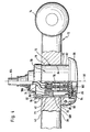
- a first embodiment as a whole designated 70 contact unit according to the invention used which is a cylindrically shaped housing sleeve 71 having insulating housing 72, in which a contact carrier 74 is fixed, which in turn electrical contacts 76, preferably contact sockets, carries.
- the insulating case 72 extends in its longitudinal direction coaxial to the transverse axis 32 and lies with a partial area 78 an outer surface 80 of its housing sleeve 71 on the cylindrical wall surface 34 of the recess 30 and will held aligned by this parallel to the transverse axis 30.
- the insulating housing 72 also stands with its housing sleeve 71 over the opening 36 with a portion 82 and has an insertion opening 84 for a contact element, preferably a contact plug, which can be closed with a cover 86 is.
- the cover 86 is by means of a pivot bearing 88 on the insulating housing 72 on one of the coupling ball 14 opposite side held pivotable about an axis 90, wherein axis 90 preferably approximately in the vertical direction is aligned.
- the pivot bearing 88 is a block over the outer lateral surface 80 of the housing sleeve 71 in the partial area 82 over and is preferably in one piece to the Insulated housing 72 molded.
- the pivot bearing 88 is also on the side 38 of the ball neck 12 in section 22 and thus also serves as Fixing the insulating housing 72 in a first direction Transverse axis 32 relative to ball neck 12.
- the insulating housing 72 is also against one Movement in an opposite second direction parallel fixed to the transverse axis 32 relative to the ball neck 12, that this on its side opposite the cover 86 can be closed with a housing cap 92, which the Outer surface 80 of the protruding through the opening 40 Section 94 of the housing sleeve 71 with a sleeve-like Approach 96 engages, which on the side 42 of the ball neck 12 is present.
- Swivel bearing 88 is thus the insulating housing 72 in the direction the transverse axis 32 is immovable relative to section 22 of the Ball neck 12 fixed.
- the housing cap 92 is either on the Insulating housing 72 can be screwed on or plugged on with a Adhesive connection can be defined or locked with it.
- the housing cap 92 preferably also has one in the Insulating housing 72 engaging extension 98, which the Contact carrier 74 against movement in the direction of the housing cap 92 fixed and at the same time preferably against creates a shoulder 100 inside the insulating housing 72.
- the smallest possible diameter around the insulating housing 72 to lend it has a radial extension with respect to the transverse axis 32, which corresponds approximately to the insertion opening 84.
- the insertion opening 84 has a diameter which corresponds to an outer diameter of a standard connector and carries a projection 85 which with an external thread of the standard plug to secure it is feasible.
- the cover 86 Plug-in opening 84 against dirt and penetration Water sealable that the lid 86 on its inside a seal 102 carries, which is in the radial direction extends so far that it with the housing sleeve 71 abuts its edge surrounding the insertion opening.
- a lead cable 104 leading to the contact unit 70 preferably penetrates the housing cap 92 and runs with it its individual veins 106 through opening 40 to the individual electrical contacts 76 in the contact carrier 74.
- a second embodiment shown in Fig. 5, are those parts with those of the embodiment are identical, provided with the same reference numerals, so that with regard to the description of the same the execution referred to the first embodiment can be.
- the outer surface 80 carries in the recess 30 engaging portion 78 projecting radially Locking lugs 110, which have correspondingly arranged locking recesses 112 engages in the wall surface 34 of the recess 30 can be brought and thus the insulating housing 72 against secure movement in the direction of the transverse axis 32 while securing the insulating case 72 in the opposite Direction parallel to the transverse axis 30 through the pivot bearing 88 he follows. Furthermore, the provision of the in the locking recesses 112 engaging locking elements 110 simultaneously another anti-rotation device of the insulating housing 72 in the recess 30 realizable.
- the supply cable runs 104 through the bottom 108 and thus through the opening 40 the recess 30.
- the insulating housing 72 is the contact unit 70 in the same way as in the first embodiment anchored in the recess 30, but extend the recesses 112 of the recess 30 from the opening 40 the same starting parallel to the transverse axis 32 deep in the Recess 30 into it so that between the opening 36 and the Locking element 110 a thin wall piece 114 as a counter bearing for the locking element 110 is used.
- the supply cable 104 is preferably not through the bottom 108 inserted into the insulating housing 72, but over a portion 116 of the insulating housing 72, which immediately adjoins the floor 108, so that in In this case, the supply cable 104 is essentially transverse or enters the insulating housing 72 at an angle to the transverse axis 32.
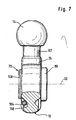
- the supply cable can be opened as in Fig. 7 shown, in a groove 118 of the ball neck 12, which extends along section 20 thereof, immediately insert into the insulating housing 72.
- the recess 30 is stepped, i.e. this extends from the opening 36 with a substantially cylindrical cross section in the Section 22 of the ball neck 12 into one of the openings 40 'surrounding ring flange surface 120 so that the opening 40 'has a smaller cross section than the opening 36.
- the supply cable 104 is fed in after as before, via a connection extending through the opening 40 ' 122 of the insulating housing 72, the connector 122 over extends the bottom 108 of the insulating housing 72.
- the one in turn against one that delimits the opening 40 ' Ring flange 128 acts so that the fixing of the insulating housing 72 ultimately takes place in that on the one hand the Bottom 108 on the annular flange surface facing the recess 30 12 of the ring flange 128 abuts and on the other hand the threaded ring 126 on an opposite side and thus ultimately the bottom 108 against which the recess 30 stepped narrowing ring flange 128 is drawn.
- FIG. 9 shows those parts with those of the previous embodiments are identical, with the same reference numerals provided so that with regard to the description of the same the explanations of the above exemplary embodiments Can be referenced.
- the contact unit for the above exemplary embodiments 70 inserted into a recess 30 ' the cylindrical Wall surfaces 34 'run coaxially to a transverse axis 32', which in this case is not perpendicular to the plane of curvature 44 of the ball neck 12, but with this one Includes angles of less than 90 °.
- the transverse axis 32 is inclined in the direction of the coupling ball 14, so that the angle of less than 90 ° between the transverse axis 32 ' and the section 24 of the ball neck 12 passing through Area of the plane of curvature 44 occurs. So that is accessibility the contact unit 70 further improved, namely characterized in that the insertion opening 84 in the direction of travel Seen motor vehicle backwards and thus lighter is accessible.
- the insulating housing 72 is attached to this Embodiment in the same way as in the fifth embodiment, namely by a threaded ring 126 and one formed by section 22 of the ball neck 12 and the Opening 40 'delimiting ring flange 128 against which the Bottom 108 of the insulating housing 72 through the threaded ring 126 is drawn.
- the ball neck in this embodiment in his Section 22 on page 42 with a reference to the Plane of curvature 44 provided asymmetrical thickening 130, which allows the recess 30 with a sufficient Form depth to prevent the insulating case 72 with its partial area 82 on page 36 too far over protrudes the ball neck in the area of section 22.
- leg 28 is so thick that the Cover 86 with its extension in the direction parallel to Plane of curvature 44 always below the upper contour 48 of the Ball neck in section 22.
Landscapes
- Engineering & Computer Science (AREA)
- Transportation (AREA)
- Mechanical Engineering (AREA)
- Pivots And Pivotal Connections (AREA)
- Connector Housings Or Holding Contact Members (AREA)
- Motor Or Generator Frames (AREA)
- Piezo-Electric Or Mechanical Vibrators, Or Delay Or Filter Circuits (AREA)
- Fluid-Damping Devices (AREA)
Description
- Fig. 1
- eine teilweise perspektivische Seitenansicht eines Kugelhalses einer Anhängekupplung für eine erfindungsgemäße Kontakteinheit;
- Fig. 2
- eine Draufsicht in Richtung des Pfeils A in Fig. 1;
- Fig. 3
- eine vergrößerte Seitenansicht des Kugelhalses gemäß Fig. 1 mit eingesetzter Kontakteinheit gemäß einem ersten Ausführungsbeispiel, welches nicht den Gegenstand des Anspruchs 1 zeigt;
- Fig. 4
- einen Schnitt längs Linie 4-4 in Fig. 3;
- Fig. 5
- eine Schnittdarstellung ähnlich Fig. 4 durch ein zweites Ausführungsbeispiel, welches nicht den Gegenstand des Anspruchs 1 zeigt;
- Fig. 6
- einen Schnitt ähnlich Fig. 4 durch ein drittes Ausführungsbeispiel;
- Fig. 7
- einen Schnitt längs Linie 7-7 in Fig. 6;
- Fig. 8
- einen Schnitt ähnlich Fig. 4 durch ein viertes Ausführungsbeispiel, welches nicht den Gegenstand des Anspruchs 1 zeigt und
- Fig. 9
- einen Schnitt ähnlich Fig. 4 durch ein fünftes Ausführungsbeispiel, welches nicht den Gegenstand des Anspruchs 1 zeigt.
Claims (23)
- Baugruppe, umfassend einen Kugelhals (12) für eine Anhängekupplung für Kraftfahrzeuge, insbesondere Personenkraftfahrzeuge, der in einem zwischen einer Halterung (10) und einer Kupplungskugel (14) liegenden Abschnitt (22) mit einer Ausnehmung (30) versehen ist, und eine Kontakteinheit (70), welche von einer seitlich des Kugelhalses (12) liegenden Öffnung (36) in den Abschnitt (22) eindringt und welche mit einer Einstecköffnung (84), mit einem Deckel (86) zum Verschließen der Einstecköffnung (84) versehen ist, dadurch gekennzeichnet, daß die Kontakteinheit (70) ein Isoliergehäuse (72) und einen in dem Isoliergehäuse (72) angeordneten sowie elektrische Kontakte (76) tragenden Kontakteinsatz (74) aufweist, daß das Isoliergehäuse (72) so ausgebildet ist, daß es zumindest mit einem Teilbereich (78) in die Ausnehmung (30) einsetzbar ist, und daß ein Zuleitungskabel (104) im wesentlichen quer oder schräg zu einer quer zur Krümmungsebene (44) des Kugelhalses 12) verlaufenden Querachse (32) in das Isoliergehäuse (72) eintritt.
- Baugruppe nach Anspruch 1 oder 2, dadurch gekennzeichnet, daß das Isoliergehäuse (72) einen den Deckel (86) tragenden Teilbereich (82) aufweist, welcher in Fortsetzung des in die Ausnehmung (30) einsetzbaren Teilbereichs (78) angeordnet ist.
- Baugruppe nach Anspruch 1 oder 2, dadurch gekennzeichnet, daß das Isoliergehäuse (72) in dem in die Ausnehmung (30) einsetzbaren Teilbereich (78) eine Außenmantelfläche (80) aufweist, welche beim Einsetzen in die Ausnehmung (30) an deren Wandfläche (34) anlegbar ist.
- Baugruppe nach einem der voranstehenden Ansprüche, dadurch gekennzeichnet, daß das Isoliergehäuse (72) ein Schwenklager (88) für den Deckel (86) aufweist, welches radial über die Außenmantelfläche (80) übersteht.
- Baugruppe nach einem der voranstehenden Ansprüche, dadurch gekennzeichnet, daß das Isoliergehäuse (72) in seinem in die Ausnehmung (30) einsetzbaren Teilbereich (78) eine Gehäusehülse (71) aufweist.
- Baugruppe nach Anspruch 5, dadurch gekennzeichnet, daß die Gehäusehülse (71) eine zylindrische Außenkontur aufweist.
- Baugruppe nach einem der Ansprüche 3 bis 6, dadurch gekennzeichnet, daß die Gehäusehülse (71) des Isoliergehäuses (72) die Außenmantelfläche (80) bildet.
- Baugruppe nach einem der Ansprüche 5 bis 7, dadurch gekennzeichnet, daß die Gehäusehülse (71) sich zu dem den Deckel (86) tragenden Teilbereich (82) erstreckt.
- Baugruppe nach Anspruch 8, dadurch gekennzeichnet, daß die Gehäusehülse (71) in dem den Deckel (86) tragenden Teilbereich (82) auf ihrer Außenseite das Schwenklager (88) für den Deckel (86) trägt.
- Baugruppe nach Anspruch 9, dadurch gekennzeichnet, daß das Schwenklager (88) für den Deckel (86) einstückig an das Isoliergehäuse (72) angeformt ist.
- Baugruppe nach einem der Ansprüche 5 bis 10, dadurch gekennzeichnet, daß ein Außendurchmesser der Gehäusehülse (71) ungefähr einem Durchmesser der Einstecköffnung (84) entspricht.
- Baugruppe nach einem der Ansprüche 8 bis 11, dadurch gekennzeichnet, daß die Gehäusehülse (71) einen die Einstecköffnung (84) umschließenden Rand bildet, an welchem eine Dichtung (102) des Deckels (86) anlegbar ist.
- Baugruppe nach einem der voranstehenden Ansprüche, dadurch gekennzeichnet, daß der in die Ausnehmung (30) einsetzbare Teilbereich (78) des Isoliergehäuses eine Länge aufweist, welche mindestens die Hälfte der axialen Länge des Isoliergehäuses (72) beträgt.
- Baugruppe nach Anspruch 13, dadurch gekennzeichnet, daß das Isoliergehäuse (72) eine derartige axiale Länge aufweist, daß dieses beiderseits der Ausnehmung (30) über diese übersteht.
- Baugruppe nach Anspruch 13 oder 14, dadurch gekennzeichnet, daß das Isoliergehäuse (72) beiderseits über den in die Ausnehmung (30) einsetzbaren Teilbereich (78) überstehende Teilbereiche (82, 94) aufweist.
- Baugruppe nach einem der voranstehenden Ansprüche, dadurch gekennzeichnet, daß das Isoliergehäuse (72) formschlüssig an dem Kugelhals (12) verankerbar ist.
- Baugruppe nach einem der voranstehenden Ansprüche, dadurch gekennzeichnet, daß das Isoliergehäuse (72) in Richtung quer zu seiner Längsachse (32) durch ein Anlegen an Wandbereichen der Ausnehmung (30) formschlüssig an dem Kugelhals (12) festlegbar ist.
- Baugruppe nach Anspruch 16 oder 17, dadurch gekennzeichnet, daß das Isoliergehäuse (72) in Richtung seiner Längsachse (32) durch an dem Kugelhals (12) anliegende Formschlußelemente (88, 96; 108, 126) formschlüssig verankert ist.
- Baugruppe nach einem der voranstehenden Ansprüche, dadurch gekennzeichnet, daß das Isoliergehäuse (72) auf einer dem Deckel (86) gegenüberliegenden Seite mit einer Gehäusekappe (92) verschließbar ist.
- Baugruppe nach Anspruch 19, dadurch gekennzeichnet, daß die Gehäusekappe (92) mit dem Isoliergehäuse (72) verrastbar ist.
- Baugruppe nach Anspruch 19, dadurch gekennzeichnet, daß die Gehäusekappe (92) mit dem Isoliergehäuse (72) mittels einer Klebeverbindung verbindbar ist.
- Baugruppe nach Anspruch 19, dadurch gekennzeichnet, daß die Gehäusekappe (92) mit dem Isoliergehäuse (72) mittels einer Schraubverbindung verbindbar ist.
- Baugruppe nach einem der Ansprüche 19 bis 22, dadurch gekennzeichnet, daß ein zur Kontakteinheit (70) führendes Zuleitungskabel (104) die Gehäusekappe durchsetzt.
Applications Claiming Priority (3)
| Application Number | Priority Date | Filing Date | Title |
|---|---|---|---|
| DE19715469A DE19715469C2 (de) | 1997-04-14 | 1997-04-14 | Anhängekupplung für Kraftfahrzeuge |
| DE19715469 | 1997-04-14 | ||
| EP98106023A EP0872364B1 (de) | 1997-04-14 | 1998-04-02 | Anhängekupplung für Kraftfahrzeuge |
Related Parent Applications (1)
| Application Number | Title | Priority Date | Filing Date |
|---|---|---|---|
| EP98106023A Division EP0872364B1 (de) | 1997-04-14 | 1998-04-02 | Anhängekupplung für Kraftfahrzeuge |
Publications (2)
| Publication Number | Publication Date |
|---|---|
| EP0873890A1 EP0873890A1 (de) | 1998-10-28 |
| EP0873890B1 true EP0873890B1 (de) | 2002-07-03 |
Family
ID=7826425
Family Applications (2)
| Application Number | Title | Priority Date | Filing Date |
|---|---|---|---|
| EP98109679A Expired - Lifetime EP0873890B1 (de) | 1997-04-14 | 1998-04-02 | Baugruppe |
| EP98106023A Expired - Lifetime EP0872364B1 (de) | 1997-04-14 | 1998-04-02 | Anhängekupplung für Kraftfahrzeuge |
Family Applications After (1)
| Application Number | Title | Priority Date | Filing Date |
|---|---|---|---|
| EP98106023A Expired - Lifetime EP0872364B1 (de) | 1997-04-14 | 1998-04-02 | Anhängekupplung für Kraftfahrzeuge |
Country Status (3)
| Country | Link |
|---|---|
| EP (2) | EP0873890B1 (de) |
| AT (2) | ATE220010T1 (de) |
| DE (3) | DE19715469C2 (de) |
Cited By (1)
| Publication number | Priority date | Publication date | Assignee | Title |
|---|---|---|---|---|
| EP3819138B1 (de) * | 2019-11-11 | 2023-09-13 | ACPS Automotive GmbH | Einbaueinheit |
Families Citing this family (15)
| Publication number | Priority date | Publication date | Assignee | Title |
|---|---|---|---|---|
| DE29814965U1 (de) † | 1998-08-21 | 1998-11-05 | Erich Jaeger GmbH & Co KG, 61350 Bad Homburg | Steckdose für mehrpolige Steckverbindung |
| DE10027573A1 (de) * | 2000-06-02 | 2001-12-06 | Oris Fahrzeugteile Riehle H | Anhängevorrichtung |
| AU2003210372A1 (en) | 2002-02-28 | 2003-09-09 | Al-Ko Kober Ag | Pivotable towing device for towing vehicles |
| DE20203270U1 (de) * | 2002-02-28 | 2003-07-10 | AL-KO Kober AG, 89359 Kötz | Schwenkbare Anhängevorrichtung für Zugfahrzeuge |
| DE20204423U1 (de) * | 2002-03-20 | 2002-07-04 | Erich Jaeger GmbH & Co. KG, 61169 Friedberg | Steckdose für elektrische Steckverbindungen |
| DE10243433A1 (de) * | 2002-09-18 | 2004-04-01 | Jaeger Cartronix Gmbh | Anhängerkupplung |
| DE102008047372A1 (de) * | 2008-09-15 | 2010-04-15 | Westfalia-Automotive Gmbh | Anhängekupplung |
| DE202009011568U1 (de) | 2009-08-26 | 2010-03-25 | Plastimat Gmbh | Steckdose für eine mehrpolige Steckvorrichtung |
| DE102009050932A1 (de) | 2009-10-28 | 2010-05-27 | Daimler Ag | Anhängerkupplungseinrichtung für einen Kraftwagen |
| DE202010003623U1 (de) * | 2010-03-16 | 2011-08-22 | Westfalia-Automotive Gmbh | Kontaktvorrichtungsanordnung für eine Anhängekupplung |
| DE202011051955U1 (de) | 2011-11-14 | 2012-02-17 | "Volta" Kraftfahrzeug-Elektrozubehör-Vertrieb GmbH | Zugfahrzeug |
| EP2738024A1 (de) * | 2012-12-03 | 2014-06-04 | Thule Towing Systems B.V. | Kupplungsvorrichtung für einen Zughaken |
| DE102014108071A1 (de) | 2014-06-06 | 2015-12-17 | Scambia Holdings Cyprus Limited | Anhängekupplung |
| DE102014118879A1 (de) * | 2014-12-17 | 2016-06-23 | Scambia Holdings Cyprus Limited | Anhängekupplung |
| DE102016117017A1 (de) | 2016-09-09 | 2018-03-15 | Westfalia-Automotive Gmbh | Anhängekupplung mit einem Kupplungsarm |
Family Cites Families (11)
| Publication number | Priority date | Publication date | Assignee | Title |
|---|---|---|---|---|
| US2658185A (en) * | 1950-05-22 | 1953-11-03 | Sr George W Hatcher | Electrical connector |
| GB835653A (en) * | 1957-05-03 | 1960-05-25 | Tatra Np | Improvements in articulating couplings for articulated vehicles |
| US3473826A (en) * | 1967-11-07 | 1969-10-21 | Big Boy Products Inc | Drawbar and ball assembly |
| GB2042316B (en) * | 1979-02-23 | 1983-02-09 | Kaitanen P | Tractor hitches |
| DE9112391U1 (de) * | 1991-10-04 | 1992-01-30 | Dambacher, Karl, Dipl.-Ing., 7080 Aalen | Kupplung |
| IT223354Z2 (it) * | 1991-11-28 | 1995-06-21 | Menber S S P A Costruzioni Ele | Connettore elettrico,particolarmente per la connessione fra un veicolotrainante ed un veicolo trainato con dispositivo antibloccaggio dei freni. |
| DE4301506A1 (de) * | 1993-01-21 | 1994-07-28 | Gebhard Dietrich | Steckdose für eine Steckverbindung für den elektrischen Anschluß von Kraftfahrzeuganhängern an Kraftfahrzeugen |
| US5580076A (en) * | 1993-09-01 | 1996-12-03 | Deroule; Yvonne H. | Automatic trailer hitch system |
| IT1262001B (it) * | 1993-09-30 | 1996-06-12 | Plini & Gigliotti Snc | Gancio di traino smontabile. |
| DE19612962A1 (de) | 1996-04-01 | 1997-10-02 | Oris Fahrzeugteile Riehle H | Anhängekupplung |
| DE19613428A1 (de) * | 1996-04-04 | 1997-10-09 | Oris Fahrzeugteile Riehle H | Anhängevorrichtung für die Anordnung an insbesondere Personenkraftwagen |
-
1997
- 1997-04-14 DE DE19715469A patent/DE19715469C2/de not_active Expired - Lifetime
-
1998
- 1998-04-02 EP EP98109679A patent/EP0873890B1/de not_active Expired - Lifetime
- 1998-04-02 AT AT98109679T patent/ATE220010T1/de not_active IP Right Cessation
- 1998-04-02 AT AT98106023T patent/ATE214342T1/de not_active IP Right Cessation
- 1998-04-02 DE DE59803311T patent/DE59803311D1/de not_active Expired - Lifetime
- 1998-04-02 DE DE59804627T patent/DE59804627D1/de not_active Expired - Lifetime
- 1998-04-02 EP EP98106023A patent/EP0872364B1/de not_active Expired - Lifetime
Cited By (1)
| Publication number | Priority date | Publication date | Assignee | Title |
|---|---|---|---|---|
| EP3819138B1 (de) * | 2019-11-11 | 2023-09-13 | ACPS Automotive GmbH | Einbaueinheit |
Also Published As
| Publication number | Publication date |
|---|---|
| ATE220010T1 (de) | 2002-07-15 |
| DE59803311D1 (de) | 2002-04-18 |
| DE19715469C2 (de) | 1999-11-18 |
| EP0872364B1 (de) | 2002-03-13 |
| ATE214342T1 (de) | 2002-03-15 |
| DE59804627D1 (de) | 2002-08-08 |
| EP0873890A1 (de) | 1998-10-28 |
| DE19715469A1 (de) | 1998-10-15 |
| EP0872364A1 (de) | 1998-10-21 |
Similar Documents
| Publication | Publication Date | Title |
|---|---|---|
| EP0872364B1 (de) | Anhängekupplung für Kraftfahrzeuge | |
| DE3812996C2 (de) | ||
| DE2704885C2 (de) | Fassungsteil für eine elektrische Steckkupplung, insbesondere eine Anhänger-Steckkupplung | |
| AT519366B1 (de) | Anschlussgehäuse und anschlusssystem | |
| WO2011095561A2 (de) | Elektrisches gerät mit einer durchführung eines kabels durch eine gehäusewand | |
| EP0692405A2 (de) | Einstellsystem für einen Reflektor eines Fahrzeug-Scheinwerfers | |
| DE3532532A1 (de) | Lenkstockschalter fuer kraftfahrzeuge | |
| DE19636477C2 (de) | Fahrzeugantenneneinrichtung | |
| DE10035996B4 (de) | Näherungsschalter | |
| DE10024029B4 (de) | Elektrische Steckverbindung | |
| DE7608649U1 (de) | Abdichtungseinrichtung für eine Anschlu Bverbjndung | |
| WO1991010270A1 (de) | Klemmvorrichtung zur herstellung einer elektrischen leitungsverbindung | |
| DE69306455T2 (de) | Elektrische Buchse für eine Anschlussklemme | |
| DE29825216U1 (de) | Kontakteinheit und Anhängekupplung für Kraftfahrzeuge mit einer Kontakteinheit | |
| EP0415136B1 (de) | Steckereinsatz für ein Metallrohrgehäuse | |
| DE19859803B4 (de) | Polklemme zur Befestigung wenigstens eines Kabels an einem Pol eines Akkumulators | |
| EP2933881A1 (de) | Hf-verbinder | |
| DE3730033C2 (de) | ||
| WO2023166085A1 (de) | Batteriesteckverbindung, bestehend aus einer einbaubuchse und einem einbaustecker | |
| DE4301506A1 (de) | Steckdose für eine Steckverbindung für den elektrischen Anschluß von Kraftfahrzeuganhängern an Kraftfahrzeugen | |
| EP0933260A2 (de) | Tank für die Aufnahme von Flüssigkeit | |
| DE10008063C2 (de) | Antennenanordnung | |
| DE3117315A1 (de) | "steckeranordnung" | |
| DE8116930U1 (de) | "Kupplungsdose mit feuchtigkeitsdichter Abdeckung" | |
| DE20017646U1 (de) | Steckverbinderanordnung |
Legal Events
| Date | Code | Title | Description |
|---|---|---|---|
| PUAI | Public reference made under article 153(3) epc to a published international application that has entered the european phase |
Free format text: ORIGINAL CODE: 0009012 |
|
| AC | Divisional application: reference to earlier application |
Ref document number: 872364 Country of ref document: EP |
|
| AK | Designated contracting states |
Kind code of ref document: A1 Designated state(s): AT BE CH DE DK ES FR GB IT LI LU NL PT SE |
|
| 17P | Request for examination filed |
Effective date: 19990415 |
|
| RBV | Designated contracting states (corrected) |
Designated state(s): AT BE CH DE DK ES FR GB IT LI LU NL PT SE |
|
| 17Q | First examination report despatched |
Effective date: 20000829 |
|
| GRAG | Despatch of communication of intention to grant |
Free format text: ORIGINAL CODE: EPIDOS AGRA |
|
| RTI1 | Title (correction) |
Free format text: SUBASSEMBLY |
|
| DAX | Request for extension of the european patent (deleted) | ||
| GRAG | Despatch of communication of intention to grant |
Free format text: ORIGINAL CODE: EPIDOS AGRA |
|
| GRAH | Despatch of communication of intention to grant a patent |
Free format text: ORIGINAL CODE: EPIDOS IGRA |
|
| GRAH | Despatch of communication of intention to grant a patent |
Free format text: ORIGINAL CODE: EPIDOS IGRA |
|
| GRAA | (expected) grant |
Free format text: ORIGINAL CODE: 0009210 |
|
| AC | Divisional application: reference to earlier application |
Ref document number: 872364 Country of ref document: EP |
|
| AK | Designated contracting states |
Kind code of ref document: B1 Designated state(s): AT BE CH DE DK ES FR GB IT LI LU NL PT SE |
|
| PG25 | Lapsed in a contracting state [announced via postgrant information from national office to epo] |
Ref country code: IT Free format text: LAPSE BECAUSE OF FAILURE TO SUBMIT A TRANSLATION OF THE DESCRIPTION OR TO PAY THE FEE WITHIN THE PRESCRIBED TIME-LIMIT;WARNING: LAPSES OF ITALIAN PATENTS WITH EFFECTIVE DATE BEFORE 2007 MAY HAVE OCCURRED AT ANY TIME BEFORE 2007. THE CORRECT EFFECTIVE DATE MAY BE DIFFERENT FROM THE ONE RECORDED. Effective date: 20020703 |
|
| REF | Corresponds to: |
Ref document number: 220010 Country of ref document: AT Date of ref document: 20020715 Kind code of ref document: T |
|
| REG | Reference to a national code |
Ref country code: CH Ref legal event code: EP |
|
| REF | Corresponds to: |
Ref document number: 59804627 Country of ref document: DE Date of ref document: 20020808 |
|
| GBT | Gb: translation of ep patent filed (gb section 77(6)(a)/1977) |
Effective date: 20020906 |
|
| PG25 | Lapsed in a contracting state [announced via postgrant information from national office to epo] |
Ref country code: SE Free format text: LAPSE BECAUSE OF FAILURE TO SUBMIT A TRANSLATION OF THE DESCRIPTION OR TO PAY THE FEE WITHIN THE PRESCRIBED TIME-LIMIT Effective date: 20021003 Ref country code: PT Free format text: LAPSE BECAUSE OF FAILURE TO SUBMIT A TRANSLATION OF THE DESCRIPTION OR TO PAY THE FEE WITHIN THE PRESCRIBED TIME-LIMIT Effective date: 20021003 Ref country code: DK Free format text: LAPSE BECAUSE OF FAILURE TO SUBMIT A TRANSLATION OF THE DESCRIPTION OR TO PAY THE FEE WITHIN THE PRESCRIBED TIME-LIMIT Effective date: 20021003 |
|
| ET | Fr: translation filed | ||
| PG25 | Lapsed in a contracting state [announced via postgrant information from national office to epo] |
Ref country code: ES Free format text: LAPSE BECAUSE OF FAILURE TO SUBMIT A TRANSLATION OF THE DESCRIPTION OR TO PAY THE FEE WITHIN THE PRESCRIBED TIME-LIMIT Effective date: 20030130 |
|
| PG25 | Lapsed in a contracting state [announced via postgrant information from national office to epo] |
Ref country code: LU Free format text: LAPSE BECAUSE OF NON-PAYMENT OF DUE FEES Effective date: 20030402 |
|
| PLAV | Examination of admissibility of opposition |
Free format text: ORIGINAL CODE: EPIDOS OPEX |
|
| PLBQ | Unpublished change to opponent data |
Free format text: ORIGINAL CODE: EPIDOS OPPO |
|
| PLBI | Opposition filed |
Free format text: ORIGINAL CODE: 0009260 |
|
| PLBQ | Unpublished change to opponent data |
Free format text: ORIGINAL CODE: EPIDOS OPPO |
|
| PLBI | Opposition filed |
Free format text: ORIGINAL CODE: 0009260 |
|
| PLAV | Examination of admissibility of opposition |
Free format text: ORIGINAL CODE: EPIDOS OPEX |
|
| PG25 | Lapsed in a contracting state [announced via postgrant information from national office to epo] |
Ref country code: LI Free format text: LAPSE BECAUSE OF NON-PAYMENT OF DUE FEES Effective date: 20030430 Ref country code: CH Free format text: LAPSE BECAUSE OF NON-PAYMENT OF DUE FEES Effective date: 20030430 |
|
| PLBF | Reply of patent proprietor to notice(s) of opposition |
Free format text: ORIGINAL CODE: EPIDOS OBSO |
|
| 26 | Opposition filed |
Opponent name: WESTFALIA-AUTOMOTIVE GMBH Effective date: 20030403 |
|
| 26 | Opposition filed |
Opponent name: JAEGER CARTRONIX GMBH Effective date: 20030403 Opponent name: WESTFALIA-AUTOMOTIVE GMBH Effective date: 20030403 |
|
| NLR1 | Nl: opposition has been filed with the epo |
Opponent name: JAEGER CARTRONIX GMBH Opponent name: WESTFALIA-AUTOMOTIVE GMBH |
|
| PLAX | Notice of opposition and request to file observation + time limit sent |
Free format text: ORIGINAL CODE: EPIDOSNOBS2 |
|
| REG | Reference to a national code |
Ref country code: CH Ref legal event code: PL |
|
| PLBB | Reply of patent proprietor to notice(s) of opposition received |
Free format text: ORIGINAL CODE: EPIDOSNOBS3 |
|
| PGFP | Annual fee paid to national office [announced via postgrant information from national office to epo] |
Ref country code: GB Payment date: 20040205 Year of fee payment: 7 |
|
| PGFP | Annual fee paid to national office [announced via postgrant information from national office to epo] |
Ref country code: AT Payment date: 20050202 Year of fee payment: 8 |
|
| PG25 | Lapsed in a contracting state [announced via postgrant information from national office to epo] |
Ref country code: GB Free format text: LAPSE BECAUSE OF NON-PAYMENT OF DUE FEES Effective date: 20050402 |
|
| PLCK | Communication despatched that opposition was rejected |
Free format text: ORIGINAL CODE: EPIDOSNREJ1 |
|
| GBPC | Gb: european patent ceased through non-payment of renewal fee |
Effective date: 20050402 |
|
| APBP | Date of receipt of notice of appeal recorded |
Free format text: ORIGINAL CODE: EPIDOSNNOA2O |
|
| APAH | Appeal reference modified |
Free format text: ORIGINAL CODE: EPIDOSCREFNO |
|
| PG25 | Lapsed in a contracting state [announced via postgrant information from national office to epo] |
Ref country code: AT Free format text: LAPSE BECAUSE OF NON-PAYMENT OF DUE FEES Effective date: 20060402 |
|
| APBQ | Date of receipt of statement of grounds of appeal recorded |
Free format text: ORIGINAL CODE: EPIDOSNNOA3O |
|
| PLAB | Opposition data, opponent's data or that of the opponent's representative modified |
Free format text: ORIGINAL CODE: 0009299OPPO |
|
| R26 | Opposition filed (corrected) |
Opponent name: JAEGER CARTRONIX GMBH Effective date: 20030403 Opponent name: WESTFALIA-AUTOMOTIVE GMBH & CO. KG Effective date: 20030403 |
|
| NLR1 | Nl: opposition has been filed with the epo |
Opponent name: JAEGER CARTRONIX GMBH Opponent name: WESTFALIA-AUTOMOTIVE GMBH & CO. KG |
|
| PGFP | Annual fee paid to national office [announced via postgrant information from national office to epo] |
Ref country code: BE Payment date: 20061010 Year of fee payment: 9 |
|
| RAP2 | Party data changed (patent owner data changed or rights of a patent transferred) |
Owner name: SCAMBIA INDUSTRIAL DEVELOPMENTS AKTIENGESELLSCHAFT |
|
| NLT2 | Nl: modifications (of names), taken from the european patent patent bulletin |
Owner name: SCAMBIA INDUSTRIAL DEVELOPMENTS AKTIENGESELLSCHAFT Effective date: 20061122 |
|
| NLS | Nl: assignments of ep-patents |
Owner name: SCAMBIA INDUSTRIAL DEVELOPMENTS AKTIENGESELLSCHAFT Effective date: 20070122 |
|
| BERE | Be: lapsed |
Owner name: *SCAMBIA INDUSTRIAL DEVELOPMENTS A.G. Effective date: 20070430 |
|
| REG | Reference to a national code |
Ref country code: FR Ref legal event code: TP |
|
| PG25 | Lapsed in a contracting state [announced via postgrant information from national office to epo] |
Ref country code: BE Free format text: LAPSE BECAUSE OF NON-PAYMENT OF DUE FEES Effective date: 20070430 |
|
| APBU | Appeal procedure closed |
Free format text: ORIGINAL CODE: EPIDOSNNOA9O |
|
| PLBN | Opposition rejected |
Free format text: ORIGINAL CODE: 0009273 |
|
| STAA | Information on the status of an ep patent application or granted ep patent |
Free format text: STATUS: OPPOSITION REJECTED |
|
| 27O | Opposition rejected |
Effective date: 20080912 |
|
| REG | Reference to a national code |
Ref country code: FR Ref legal event code: TP Owner name: SCAMBIA HOLDINGS CYPRUS LIMITED, CY Effective date: 20150105 |
|
| REG | Reference to a national code |
Ref country code: NL Ref legal event code: SD Effective date: 20150312 |
|
| REG | Reference to a national code |
Ref country code: DE Ref legal event code: R082 Ref document number: 59804627 Country of ref document: DE Representative=s name: HOEGER, STELLRECHT & PARTNER PATENTANWAELTE, DE |
|
| REG | Reference to a national code |
Ref country code: DE Ref legal event code: R082 Ref document number: 59804627 Country of ref document: DE Representative=s name: HOEGER, STELLRECHT & PARTNER PATENTANWAELTE MB, DE Effective date: 20150407 Ref country code: DE Ref legal event code: R082 Ref document number: 59804627 Country of ref document: DE Representative=s name: HOEGER, STELLRECHT & PARTNER PATENTANWAELTE, DE Effective date: 20150407 Ref country code: DE Ref legal event code: R081 Ref document number: 59804627 Country of ref document: DE Owner name: BOSAL ACPS HOLDING 2 B.V., NL Free format text: FORMER OWNER: SCAMBIA INDUSTRIAL DEVELOPMENTS AKTIENGESELLSCHAFT, SCHAAN, LI Effective date: 20150407 Ref country code: DE Ref legal event code: R081 Ref document number: 59804627 Country of ref document: DE Owner name: SCAMBIA HOLDINGS CYPRUS LTD., CY Free format text: FORMER OWNER: SCAMBIA INDUSTRIAL DEVELOPMENTS AKTIENGESELLSCHAFT, SCHAAN, LI Effective date: 20150407 |
|
| REG | Reference to a national code |
Ref country code: DE Ref legal event code: R082 Ref document number: 59804627 Country of ref document: DE Representative=s name: HOEGER, STELLRECHT & PARTNER PATENTANWAELTE MB, DE |
|
| REG | Reference to a national code |
Ref country code: FR Ref legal event code: PLFP Year of fee payment: 19 |
|
| REG | Reference to a national code |
Ref country code: FR Ref legal event code: PLFP Year of fee payment: 20 |
|
| PGFP | Annual fee paid to national office [announced via postgrant information from national office to epo] |
Ref country code: NL Payment date: 20170419 Year of fee payment: 20 |
|
| PGFP | Annual fee paid to national office [announced via postgrant information from national office to epo] |
Ref country code: DE Payment date: 20170419 Year of fee payment: 20 Ref country code: FR Payment date: 20170419 Year of fee payment: 20 |
|
| REG | Reference to a national code |
Ref country code: DE Ref legal event code: R082 Ref document number: 59804627 Country of ref document: DE Representative=s name: HOEGER, STELLRECHT & PARTNER PATENTANWAELTE MB, DE Ref country code: DE Ref legal event code: R081 Ref document number: 59804627 Country of ref document: DE Owner name: BOSAL ACPS HOLDING 2 B.V., NL Free format text: FORMER OWNER: SCAMBIA HOLDINGS CYPRUS LTD., LIMASSOL, CY |
|
| REG | Reference to a national code |
Ref country code: DE Ref legal event code: R071 Ref document number: 59804627 Country of ref document: DE |
|
| REG | Reference to a national code |
Ref country code: NL Ref legal event code: MK Effective date: 20180401 |