EP0873437B1 - Verfahren zum formen eines spinn- oder zwirnringes sowie nach dem verfahren geformter spinn- oder zwirnring - Google Patents
Verfahren zum formen eines spinn- oder zwirnringes sowie nach dem verfahren geformter spinn- oder zwirnring Download PDFInfo
- Publication number
- EP0873437B1 EP0873437B1 EP96942229A EP96942229A EP0873437B1 EP 0873437 B1 EP0873437 B1 EP 0873437B1 EP 96942229 A EP96942229 A EP 96942229A EP 96942229 A EP96942229 A EP 96942229A EP 0873437 B1 EP0873437 B1 EP 0873437B1
- Authority
- EP
- European Patent Office
- Prior art keywords
- flange
- web
- spinning
- area
- ring
- Prior art date
- Legal status (The legal status is an assumption and is not a legal conclusion. Google has not performed a legal analysis and makes no representation as to the accuracy of the status listed.)
- Expired - Lifetime
Links
- 238000000034 method Methods 0.000 title claims description 40
- 238000009987 spinning Methods 0.000 title claims description 18
- 239000000463 material Substances 0.000 claims description 26
- 229910000831 Steel Inorganic materials 0.000 claims description 16
- 239000010959 steel Substances 0.000 claims description 16
- 230000015572 biosynthetic process Effects 0.000 claims description 5
- 230000007423 decrease Effects 0.000 claims description 4
- 238000003825 pressing Methods 0.000 claims description 3
- 238000000641 cold extrusion Methods 0.000 claims 2
- 238000010791 quenching Methods 0.000 claims 1
- 239000007787 solid Substances 0.000 claims 1
- 238000004080 punching Methods 0.000 description 7
- 238000005520 cutting process Methods 0.000 description 6
- 238000004049 embossing Methods 0.000 description 5
- 238000003754 machining Methods 0.000 description 5
- 238000000465 moulding Methods 0.000 description 5
- 238000007493 shaping process Methods 0.000 description 5
- 230000006835 compression Effects 0.000 description 3
- 238000007906 compression Methods 0.000 description 3
- 238000004519 manufacturing process Methods 0.000 description 3
- 238000009826 distribution Methods 0.000 description 2
- 238000001125 extrusion Methods 0.000 description 2
- 239000000835 fiber Substances 0.000 description 2
- 238000009499 grossing Methods 0.000 description 2
- 238000010409 ironing Methods 0.000 description 2
- 238000005498 polishing Methods 0.000 description 2
- 238000012805 post-processing Methods 0.000 description 2
- 239000007858 starting material Substances 0.000 description 2
- 238000005482 strain hardening Methods 0.000 description 2
- 238000013459 approach Methods 0.000 description 1
- 238000005452 bending Methods 0.000 description 1
- 238000005056 compaction Methods 0.000 description 1
- 239000012634 fragment Substances 0.000 description 1
- 238000010438 heat treatment Methods 0.000 description 1
- 238000009434 installation Methods 0.000 description 1
- 238000012545 processing Methods 0.000 description 1
- 239000011343 solid material Substances 0.000 description 1
Images
Classifications
-
- D—TEXTILES; PAPER
- D01—NATURAL OR MAN-MADE THREADS OR FIBRES; SPINNING
- D01H—SPINNING OR TWISTING
- D01H7/00—Spinning or twisting arrangements
- D01H7/02—Spinning or twisting arrangements for imparting permanent twist
- D01H7/52—Ring-and-traveller arrangements
- D01H7/60—Rings or travellers; Manufacture thereof not otherwise provided for ; Cleaning means for rings
- D01H7/602—Rings
-
- B—PERFORMING OPERATIONS; TRANSPORTING
- B21—MECHANICAL METAL-WORKING WITHOUT ESSENTIALLY REMOVING MATERIAL; PUNCHING METAL
- B21D—WORKING OR PROCESSING OF SHEET METAL OR METAL TUBES, RODS OR PROFILES WITHOUT ESSENTIALLY REMOVING MATERIAL; PUNCHING METAL
- B21D53/00—Making other particular articles
- B21D53/16—Making other particular articles rings, e.g. barrel hoops
Definitions
- the invention relates to a method for molding a spinning or twisting ring according to the preamble of Claim 1 as well as on a non-cutting spinning or Thread ring, with T-shaped profile.
- flange ring uses its parts as a flange and the bridge. Those surfaces on the flange with which the runner cooperates in spinning or twisting, and their profile accuracy and surface quality from Significance are hereinafter referred to as functional areas or functional profiles.
- Known methods for forming a flange ring exist usually from machining operations. Went out is made of tubular rods made of ball bearing or case hardening steel. On multi-spindle machines or CNC machines a corresponding ring profile is worked out from a turning blank, the turning blank being formed by parting off must become.
- a generic method, in which from steel a blank disc is punched out, the blank disc below Formation of a base area deep-drawn in a cup shape, and A circular disc is punched out centrally on the base area is known from GB-A-692 399.
- the object of the invention is to create a method to form a high quality flange ring that both regarding procedural operations as well as regarding Material expenditure for the same is economical.
- the invention lies primarily in the knowledge that exclusively by strip forming, i.e. by drawing and Press operations, a flange ring with sufficient material transfer to form the flange.
- the finished flange ring form is the manufacture corresponding quantities extremely cost-effective. machining Edits are unnecessary, at least to the extent that than the essential dimensions of a flange ring ISO 96-1: 1992 (referred to there as the T-ring) are affected.
- the forming operations themselves, as well as the punching operations, can be carried out without reclamping.
- the punching process to separate the circular disc from the web side done here. So the shear edge comes inward projecting flange shoulder to lie on the top of the flange, i.e. into a material zone that, even after pressing, not in an essential part of the flange and there is no load on the runner during operation experiences.
- edge areas of the Flange given predetermined functional profiles. With that leaves post-processing by turning or grinding avoid entirely. It has been shown that with these Operations accurate profiling, as well as smooth Surface of the functional surfaces is accessible. Avoidance related post-processing by turning or grinding again saves considerable costs to. Finally, the extrusion works immediately on improving the Wear properties.
- the invention also includes one by cold working completely non-cutting spinning or twisted ring, which is full-walled according to the invention and also through a special distribution of the grain sizes on the ring cross-section distinguished.
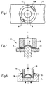
- a partially punched-out round disk is held as a blank disk 12 by means of a net holder 14a, 14b obtained by net punching.
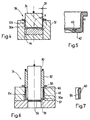
- a hump 16 is formed in the center of the blank disc 12, which forms the basis for a blank for producing a spinning or twisting ring.
- the first deep-drawing tool 22 shown in FIG. 2 and having a die 18 and a stamp 20 is used to form the hump 16 .
- the blank disc 12 shown in FIG. 2 is formed into a cup-shaped blank 12a , an at least approximately cylindrical wall being formed as a web area 30 .
- the blank 12a is still connected to the steel strip 10 by means of the net holder 14a, 14b shown in FIG. 1, but the webs of the net holder 14a, 14b are pulled apart compared to the illustration in FIG. 1 because the outer diameter of the Edge on the blank 12a becomes smaller by the second deep-drawing process.
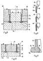
- the tool 36 shown in FIG. 4, having a die 32 and a punch 34 , is used for ironing the blank 12b and for pressing the hump 16 shown in FIG. 2 flat.
- the web area 30a is stretched on the one hand, so that whose wall thickness 38 is reduced to 0.8 mm, for example.
- a controlled material flow in the direction of the arrow 40 according to FIG. 5 takes place from the center into the edge region 42 .
- an annular recess 44 is arranged in the die 32 .
- the blank 12b is still connected to the steel strip 10 according to FIG. 1 by means of the net holder 14a, 14b in this method step.
- the material shift into the edge area 42 serves as a preliminary stage for the formation of an annular flange.
- the punching tool 54 shown in FIG. 6 and having a die 48 and a double punch 50 , 52 is used in order first to punch away the edge 58 and second to punch out a circular disk 56 from the bottom area 57 of the blank 12c forming the flange side . After the circular disk 56 has been punched out, a radially inwardly projecting flange shoulder 59 remains on the bottom region 57 .
- the double stamp 50, 52 can be designed as a follow-up tool, or it can be stamps which can be actuated separately from one another.
- the blank 12c is separated from the steel strip 10 by punching out the edge 58 .
- the punching out of the circular disk 56 from the web side serves for rough shaping of the inner ring diameter.
- the blank 12c was connected to the steel strip 10 shown in FIG. 1 by means of the net holder 14a , 14b .
- the holding of the blank disc 12 in the respective process step on the strip steel 10 served for the feed to the subsequent work station.
- FIG. 7 shows a detail in an enlarged representation of the cutting edge 60 after the edge 58 has been punched away.
- the embossing and deep-drawing tool 68 shown in FIG. 8 having a die 62, a core punch 64 and a ring punch 66 , is used on the blank 12d for stamping or smoothing the non-functional cutting edge 60 (FIGS. 7, 9), for tapering the outside diameter of the web area from 30a (FIG. 6) to 30b (FIG. 8) by deep drawing and for preforming the flange region 70.
- the web region 30b is also compressed during this process.
- the die 62 has an annular recess 71 for receiving and preforming the flange region 70 .
- the flange region 70 of the blank 12d consists of the radially inwardly projecting flange projection 59 and a radially outwardly projecting flange projection 73 .
- the core punch 64 essentially serves to hold the blank 12d on the die 62 and to fix its inside diameter.
- An annular embossing and drawing edge 66a arranged on the inner edge of the ring stamp 66 according to FIG. 9 serves both for embossing or smoothing the cutting edge 60 of the blank 12d and for tapering its outer diameter.
- the stamping and deep-drawing process results in a controlled material flow from the web area 30b into the flange area 70.
- the length of the web area 30b decreases.
- the compression of the material in the flange area 70 which is connected with the material flow and is thereby solidified is particularly advantageous. As a result of the reduction in the diameter of the web area 30b , the material in this can also be compressed.
- FIG 9 illustrates the continuous embossing and deep-drawing process in which the ring stamp 66 is moved in the direction of arrow 74 in three successive individual images.
- the tool 76 shown in section in FIG. 10 has a die 78 , a core punch 80 and a ring punch 82 . It essentially serves for the final shaping of the functional surfaces of the flange ring 84 .
- the T-shaped profile of the flange ring 84 is formed by a web 86 and a flange 88 .
- the flange 88 is extruded from the flange region 70 , both the radially inwardly projecting flange shoulder 59 and the radially outwardly projecting flange shoulder 73 being rounded.
- flange 88 The flattened top of flange 88 is the downward side in the drawings because the flange ring is directed downward with flange 88 during the molding process, as opposed to its installation position.
- the flange approaches 59, 73 convexly shaped functional profiles 72, 73a between the web area 30b and the flange top.
- the flange ring hardened or surface hardened.
- the molding method according to the invention is suitable for Flange rings of different sizes and enables considerable material and cost savings.
- the so produced Flange rings are made of full material instead turned flange rings ready for use.
- the also inventive, non-cutting and complete spinning or twisting ring produced by cold forming T-profile, comprising a web and a flange, approximately according to Fig. 11 differs from that by machining rings produced once by the material of the Bridges practically connected over its full cross section merges into the flange. At least this is before a heat treatment, such as hardening occurring, noticeable on the course of the fibers.
- Such a full-walled ring is therefore not only different from e.g. rings produced solely by turning or by shaping and turning (DE-A1-195 03 321), in which fibers be cut, but also by the chipless manufactured rings in which the flange through Bending steps were molded.
- DE-A1-195 03 321 in which fibers be cut, but also by the chipless manufactured rings in which the flange through Bending steps were molded.
- GB-PS 692'399 directed.
- a full-walled flange ring according to the invention produce is usually one of strip steel thermoformable quality, one Deep drawing deformation followed by compression and compression steps, by means of which the flange is molded. After Such a ring is shaped by case hardening and Polishing finished.
- This also leaves the service life of the Ring favoring greater Brinell hardness on the flange surface to reach. It can be said generally: that the grain size in the flange (88) from the inside (90) to Surface (92) and towards the web (86) by at least 20% decreases.
- the mean size difference is about a factor of 2 or greater.
Landscapes
- Engineering & Computer Science (AREA)
- Mechanical Engineering (AREA)
- Textile Engineering (AREA)
- Shaping Metal By Deep-Drawing, Or The Like (AREA)
- Forging (AREA)
- Spinning Or Twisting Of Yarns (AREA)
Description
- Fig. 1
- ein Teilstück eines Bandstahls mit vorgestanzter, mittels Netzhalterung darin gehaltener Rohlingscheibe,
- Fig. 2
- die Anformung eines Buckels im Zentrum der Rohlingscheibe durch einen ersten Tiefziehvorgang,
- Fig. 3
- einen zweiten Tiefziehvorgang zur Bildung des mindestens annähernd zylindrischen Teils des Ringrohlings,
- Fig. 4
- einen Abstreckziehvorgang mit kontrolliertem Materialfluss und das Flachpressen des Buckels durch Kaltfliessen in den Randbereich zum Vorformen des Ringflansches,
- Fig. 5
- einen Ausschnitt aus dem Randbereich nach Fig. 4 in vergrösserter Darstellung,
- Fig. 6
- einen Folgestanzvorgang als Grobformgebung des Ringinnendurchmessers und zum Ablösen des Ringrohlings vom Bandstahl,
- Fig. 7
- den dem Flanschbereich entgegengesetzten Randbereich mit der Stanzkante nach Fig. 6, in vergrösserter Darstellung,
- Fig. 8
- einen Prägevorgang der nichtfunktionellen Stanzkante, Verjüngung des Aussendurchmessers durch Ziehen, kontrollierter Materialfluss in den Flanschbereich sowie Reduktion der Steglänge zur Erhöhung der Materialverfügbarkeit im Flanschbereich,
- Fig. 9
- die Verjüngung des Aussendurchmessers durch die gerundete Innenkante des Ziehwerkzeuges, dargestellt in drei untereinanderfolgenden Ansichten,
- Fig. 10
- einen Fliesspressvorgang zur Endformgebung der Funktionsflächen des Flanschbereiches und
- Fig. 11
- ein Ausführungsbeispiel eines erfindungsgemässen Flanschringes.
Der Kernstempel 64 dient im wesentlichen zum Halten des Rohlings 12d auf der Matrize 62 und zum Festlegen seines Innendurchmessers. Eine am Innenrand des Ringstempels 66 gemäss Fig. 9 angeordnete ringförmige Präge- und Ziehkante 66a dient sowohl zum Prägen bzw. Glätten der Schnittkante 60 des Rohlings 12d als auch zum Verjüngen seines Aussendurchmessers.
Claims (13)
- Verfahren zum Formen eines Spinn- oder Zwirnringes, mit einem T-förmigen Profil, bei dem aus Bandstahl (10) eine Rohlingscheibe ausgestanzt und die Rohlingscheibe unter Bildung eines Bodenbereiches (57) becherförmig tiefgezogen und am Bodenbereich (57) eine Kreisscheibe (56) zentrisch ausgestanzt wird, dadurch gekennzeichnet, dass die Rohlingscheibe (12) unter gleichzeitiger Bildung eines ringförmigen Stegbereiches (30, 30a) tiefgezogen wird, beim zentrischen Ausstanzen der Kreisscheibe (56) ein Ring mit radial einwärts ragendem Flanschansatz (59) gebildet wird und durch Stauchpressen der am Stegbereich (30, 30a) verbliebene Bodenbereich (57) zu einer abgeflachten Flanschoberseite geformt sowie ein radial auswärts ragender Flanschansatz (73) gebildet wird, wobei sowohl aus dem Bodenbereich (57) vor dem Ausstanzen der Kreisscheibe (56), wie aus dem Stegbereich (30, 30a) Material in den Flanschbereich (70) verdrängt wird.
- Verfahren nach Anspruch 1, dadurch gekennzeichnet, dass das Ausstanzen der Kreisscheibe (56) von der Stegseite her erfolgt.
- Verfahren nach Anspruch 1 oder 2, dadurch gekennzeichnet, dass an der Rohlingscheibe (12) durch Tiefziehen ein zentraler Buckel (16) gebildet und nach dem becherförmigen Tiefziehen durch Kaltfliesspressen zumindest das Buckelmaterial im Bodenbereich (57) radial nach aussen in den Flanschbereich (70, 73) verdrängt wird.
- Verfahren nach Anspruch 2 oder 3, dadurch gekennzeichnet, dass unter Stauchung des Stegbereiches (30b) in axialer Richtung dem Flanschbereich (70, 73) Stegmaterial zugeführt wird.
- Verfahren nach einem der vorstehenden Ansprüche, dadurch gekennzeichnet, dass durch Fliesspressen den Flanschansätzen (72, 73) zwischen Stegbereich (30b) und Flanschoberseite konvex geformte Funktionsprofile erteilt werden.
- Verfahren nach einem der vorstehenden Ansprüche, dadurch gekennzeichnet, dass der Stegbereich (30b) unterhalb des Flanschansatzes (70, 73) durch Abstreckziehen im Durchmesser verjüngt wird.
- Verfahren nach einem der vorstehenden Ansprüche, dadurch gekennzeichnet, dass der durch Netzstanzung (14a, 14b) mit dem Bandstahl (10) verbundene Rohling (12, 12a, 12b) über mehrere Operationen durch Vorschub des Bandstahles (10) weiterbefördert wird.
- Verfahren zur Herstellung eines Spinn- oder Zwirnringes, der nach einem der vorstehenden Ansprüche geformt wird, dadurch gekennzeichnet, dass der geformte Spinn- oder Zwirnring gehärtet wird.
- Spinn- oder Zwirnring, geformt nach dem Verfahren nach einem der Ansprüche 1 bis 7.
- Spinn- oder Zwirnring, hergestellt nach dem Verfahren gemäss Anspruch 8.
- Spinn-oder Zwirnring mit T-Profil, erhältlich nach einem Verfahren nach einem der Ansprüche 1-9, umfassend einen Steg (86) und einen Flansch (88), dadurch gekennzeichnet, dass das Material des Steges praktisch über dessen vollen Querschnitt zusammenhängend in den Flansch übergeht.
- Spinn-oder Zwirnring mit T-Profil, umfassend einen Steg (86) und einen Flansch (88), dadurch. gekennzeichnet, dass die mittlere Korngrösse im Flansch vom Innern zur Oberfläche hin um mindestens 20% abnimmt.
- Spinn-oder Zwirnring mit T-Profil, mit einen Steg und einem daran anschliessenden Flansch, wobei der Flansch vollwandig ist, das Material des Steges praktisch üher dessen vollen Querschnitt zusammenhängend in den Flansch übergeht und wobei die mittlere Korngrösse im Flansch von dessen Innern zur Oberfläche hin um mindestens 20% abnimmt.
Applications Claiming Priority (4)
| Application Number | Priority Date | Filing Date | Title |
|---|---|---|---|
| CH3690/95 | 1995-12-28 | ||
| CH03690/95A CH690779A5 (de) | 1995-12-28 | 1995-12-28 | Verfahren zum Formen eines Spinn- oder Zwirnringes sowie nach dem Verfahren geformter Spinn- oder Zwirnring. |
| CH369095 | 1995-12-28 | ||
| PCT/CH1996/000459 WO1997024477A1 (de) | 1995-12-28 | 1996-12-23 | Verfahren zum formen eines spinn- oder zwirnringes sowie nach dem verfahren geformter spinn- oder zwirnring |
Publications (2)
| Publication Number | Publication Date |
|---|---|
| EP0873437A1 EP0873437A1 (de) | 1998-10-28 |
| EP0873437B1 true EP0873437B1 (de) | 2002-05-02 |
Family
ID=4261430
Family Applications (1)
| Application Number | Title | Priority Date | Filing Date |
|---|---|---|---|
| EP96942229A Expired - Lifetime EP0873437B1 (de) | 1995-12-28 | 1996-12-23 | Verfahren zum formen eines spinn- oder zwirnringes sowie nach dem verfahren geformter spinn- oder zwirnring |
Country Status (7)
| Country | Link |
|---|---|
| EP (1) | EP0873437B1 (de) |
| JP (1) | JP3954104B2 (de) |
| CN (1) | CN1082105C (de) |
| CH (1) | CH690779A5 (de) |
| DE (1) | DE59609165D1 (de) |
| TR (1) | TR199801231T2 (de) |
| WO (1) | WO1997024477A1 (de) |
Cited By (2)
| Publication number | Priority date | Publication date | Assignee | Title |
|---|---|---|---|---|
| WO2018046473A1 (de) * | 2016-09-07 | 2018-03-15 | Thyssenkrupp Steel Europe Ag | Verfahren und werkzeug zur herstellung von blechbauteilen |
| US11097330B2 (en) | 2016-09-29 | 2021-08-24 | Thyssenkrupp Steel Europe Ag | Method for producing a formed component having a dimensionally accurate wall region |
Families Citing this family (6)
| Publication number | Priority date | Publication date | Assignee | Title |
|---|---|---|---|---|
| WO2000074612A1 (en) * | 1999-06-03 | 2000-12-14 | Dj Orthopedics, Llc | D-rings for braces |
| EP1302571B1 (de) * | 2001-10-11 | 2007-05-02 | Kanai Juyo Kogyo Company Limited | Spinnring für eine Ringspinnmaschine und Verfahren zur dessen Herstellung |
| US6568164B2 (en) | 2001-10-12 | 2003-05-27 | Kanai Juyo Kogyo Co., Ltd. | Spinning ring for a ring spinning machine and method of manufacturing thereof |
| DE102009059197A1 (de) * | 2009-12-17 | 2011-06-22 | ThyssenKrupp Steel Europe AG, 47166 | Verfahren und Vorrichtung zur Herstellung eines Halbschalenteils |
| CH706605A1 (de) * | 2012-06-08 | 2013-12-13 | Braecker Ag | Spinn- oder Zwirnring. |
| CN112845869B (zh) * | 2020-12-31 | 2022-03-22 | 铭昊汽车金属零部件(广州)有限公司 | 异形管件成型模具和成型工艺 |
Family Cites Families (5)
| Publication number | Priority date | Publication date | Assignee | Title |
|---|---|---|---|---|
| US1351595A (en) * | 1919-10-21 | 1920-08-31 | Charles D White | Spinning-ring |
| BE504845A (de) * | 1950-07-28 | |||
| GB692399A (en) * | 1951-03-28 | 1953-06-03 | Juan Sape Roch | Improvements in or relating to rings for ring spinning and doubling frames |
| US3236040A (en) * | 1962-10-03 | 1966-02-22 | Schwabische Formdrehteile G M | Spinning or twisting ring |
| DE19503321A1 (de) * | 1995-02-02 | 1996-01-04 | Braecker Ag | Verfahren zur Herstellung eines Spinn- oder Zwirnringes und nach dem Verfahren hergestellter Spinn- oder Zwirnring |
-
1995
- 1995-12-28 CH CH03690/95A patent/CH690779A5/de not_active IP Right Cessation
-
1996
- 1996-12-23 TR TR1998/01231T patent/TR199801231T2/xx unknown
- 1996-12-23 DE DE59609165T patent/DE59609165D1/de not_active Expired - Lifetime
- 1996-12-23 JP JP52394497A patent/JP3954104B2/ja not_active Expired - Fee Related
- 1996-12-23 CN CN96198587A patent/CN1082105C/zh not_active Expired - Fee Related
- 1996-12-23 WO PCT/CH1996/000459 patent/WO1997024477A1/de not_active Ceased
- 1996-12-23 EP EP96942229A patent/EP0873437B1/de not_active Expired - Lifetime
Cited By (2)
| Publication number | Priority date | Publication date | Assignee | Title |
|---|---|---|---|---|
| WO2018046473A1 (de) * | 2016-09-07 | 2018-03-15 | Thyssenkrupp Steel Europe Ag | Verfahren und werkzeug zur herstellung von blechbauteilen |
| US11097330B2 (en) | 2016-09-29 | 2021-08-24 | Thyssenkrupp Steel Europe Ag | Method for producing a formed component having a dimensionally accurate wall region |
Also Published As
| Publication number | Publication date |
|---|---|
| JP2000502758A (ja) | 2000-03-07 |
| JP3954104B2 (ja) | 2007-08-08 |
| CH690779A5 (de) | 2001-01-15 |
| DE59609165D1 (de) | 2002-06-06 |
| TR199801231T2 (xx) | 1998-10-21 |
| CN1202938A (zh) | 1998-12-23 |
| WO1997024477A1 (de) | 1997-07-10 |
| EP0873437A1 (de) | 1998-10-28 |
| CN1082105C (zh) | 2002-04-03 |
| HK1017028A1 (en) | 1999-11-12 |
Similar Documents
| Publication | Publication Date | Title |
|---|---|---|
| DE4442269B4 (de) | Käfig für ein Rollenlager und Verfahren zu dessen Herstellung | |
| DE69001390T2 (de) | Verfahren und vorrichtung zur formgebung von hohlkoerpern durch abstreck-gleitziehen der wand. | |
| DE69106760T2 (de) | Verfahren zum Herstellen eines Reibringes. | |
| DE4419591A1 (de) | Verfahren zur Herstellung eines plastisch geformten Produkts | |
| DE19982876B4 (de) | Verfahren für den Betrieb eines Presswerkzeuges einer Stanzpresse, Presswerkzeug sowie deren Verwendung | |
| EP1919643A1 (de) | Verfahren, fertigungslinie und kolbenrohling zum herstellen eines einteilig ausgebildeten kolbens für verbrennungsmotoren, sowie kolben für verbrennungsmotoren | |
| WO2001058616A1 (de) | Verfahren und drückwalzvorrichtung zum herstellen eines hohlkörpers | |
| EP1414613B1 (de) | Hydraulikkolben aus walzblech und verfahren zu dessen herstellung | |
| DE2228986A1 (de) | Verfahren und Vorrichtung zum Kalt fließpressen von Anschlußstucken | |
| DE60209662T2 (de) | Herstellungsverfahren eines Innen- und Aussenlagerringes | |
| WO2005051594A2 (de) | Kaltumformverfahren zur herstellung von kugelzapfen | |
| EP0873437A1 (de) | Verfahren zum formen eines spinn- oder zwirnringes sowie nach dem verfahren geformter spinn- oder zwirnring | |
| DE102015118495A1 (de) | Verfahren zur Herstellung eines Ventilstößels sowie Ventilstößel | |
| EP2148752B1 (de) | Verfahren zur herstellung von hohlwellengrundkörpern | |
| DE19820864A1 (de) | Mechanischer Bleistift mit Doppelspannfutter | |
| EP0639415B1 (de) | Verfahren zum Herstellen eines rotationssymmetrischen Körpers | |
| DE10121546B4 (de) | Verfahren und Drückrolle zum Anformen einer Nabe | |
| DE19503321A1 (de) | Verfahren zur Herstellung eines Spinn- oder Zwirnringes und nach dem Verfahren hergestellter Spinn- oder Zwirnring | |
| DE112006001748T5 (de) | Verfahren zum Herstellen eines ringförmigen Elements und mit Zinken versehenes ringförmiges Element | |
| DE102005028093B3 (de) | Verfahren zur gleichzeitigen Herstellung eines Kegelrollenlagerinnenrings und eines Kegelrollenlageraußenrings | |
| DE69901702T2 (de) | Herstellungsverfahren für ein rohrförmiges metallisches Bauteil und eine rohrförmige Verbundwelle | |
| DE3101123A1 (de) | Verfahren und einrichtung zum verformen eines metallstabes in ein tulpenfoermiges teil durch fliesspressen in einer geschlossenen kammer | |
| DE102004004233C5 (de) | Verfahren und Vorrichtung zur Herstellung einer Dehnschraube | |
| DE10344885B3 (de) | Verfahren zum Herstellen eines Werkstücks mit Nabe mittels einer Presse und Blechwerkstück | |
| DE3404877A1 (de) | Verfahren zur herstellung von kugelzapfen |
Legal Events
| Date | Code | Title | Description |
|---|---|---|---|
| PUAI | Public reference made under article 153(3) epc to a published international application that has entered the european phase |
Free format text: ORIGINAL CODE: 0009012 |
|
| 17P | Request for examination filed |
Effective date: 19980228 |
|
| AK | Designated contracting states |
Kind code of ref document: A1 Designated state(s): CH DE GB GR IT LI |
|
| 17Q | First examination report despatched |
Effective date: 19990914 |
|
| GRAG | Despatch of communication of intention to grant |
Free format text: ORIGINAL CODE: EPIDOS AGRA |
|
| GRAG | Despatch of communication of intention to grant |
Free format text: ORIGINAL CODE: EPIDOS AGRA |
|
| GRAH | Despatch of communication of intention to grant a patent |
Free format text: ORIGINAL CODE: EPIDOS IGRA |
|
| GRAH | Despatch of communication of intention to grant a patent |
Free format text: ORIGINAL CODE: EPIDOS IGRA |
|
| REG | Reference to a national code |
Ref country code: GB Ref legal event code: IF02 |
|
| GRAA | (expected) grant |
Free format text: ORIGINAL CODE: 0009210 |
|
| AK | Designated contracting states |
Kind code of ref document: B1 Designated state(s): CH DE GB GR IT LI |
|
| REG | Reference to a national code |
Ref country code: GB Ref legal event code: FG4D Free format text: NOT ENGLISH |
|
| REG | Reference to a national code |
Ref country code: CH Ref legal event code: EP |
|
| REG | Reference to a national code |
Ref country code: CH Ref legal event code: NV Representative=s name: PATENTANWAELTE SCHAAD, BALASS, MENZL & PARTNER AG |
|
| REF | Corresponds to: |
Ref document number: 59609165 Country of ref document: DE Date of ref document: 20020606 |
|
| GBT | Gb: translation of ep patent filed (gb section 77(6)(a)/1977) |
Effective date: 20020731 |
|
| REG | Reference to a national code |
Ref country code: GR Ref legal event code: EP Ref document number: 20020402283 Country of ref document: GR |
|
| PLBE | No opposition filed within time limit |
Free format text: ORIGINAL CODE: 0009261 |
|
| STAA | Information on the status of an ep patent application or granted ep patent |
Free format text: STATUS: NO OPPOSITION FILED WITHIN TIME LIMIT |
|
| 26N | No opposition filed |
Effective date: 20030204 |
|
| PGFP | Annual fee paid to national office [announced via postgrant information from national office to epo] |
Ref country code: GB Payment date: 20071218 Year of fee payment: 12 |
|
| PGFP | Annual fee paid to national office [announced via postgrant information from national office to epo] |
Ref country code: GR Payment date: 20071219 Year of fee payment: 12 |
|
| GBPC | Gb: european patent ceased through non-payment of renewal fee |
Effective date: 20081223 |
|
| PG25 | Lapsed in a contracting state [announced via postgrant information from national office to epo] |
Ref country code: GB Free format text: LAPSE BECAUSE OF NON-PAYMENT OF DUE FEES Effective date: 20081223 |
|
| PG25 | Lapsed in a contracting state [announced via postgrant information from national office to epo] |
Ref country code: GR Free format text: LAPSE BECAUSE OF NON-PAYMENT OF DUE FEES Effective date: 20090703 |
|
| PGFP | Annual fee paid to national office [announced via postgrant information from national office to epo] |
Ref country code: CH Payment date: 20121221 Year of fee payment: 17 |
|
| REG | Reference to a national code |
Ref country code: CH Ref legal event code: PL |
|
| PG25 | Lapsed in a contracting state [announced via postgrant information from national office to epo] |
Ref country code: CH Free format text: LAPSE BECAUSE OF NON-PAYMENT OF DUE FEES Effective date: 20131231 Ref country code: LI Free format text: LAPSE BECAUSE OF NON-PAYMENT OF DUE FEES Effective date: 20131231 |
|
| PGFP | Annual fee paid to national office [announced via postgrant information from national office to epo] |
Ref country code: DE Payment date: 20141211 Year of fee payment: 19 |
|
| PGFP | Annual fee paid to national office [announced via postgrant information from national office to epo] |
Ref country code: IT Payment date: 20141223 Year of fee payment: 19 |
|
| REG | Reference to a national code |
Ref country code: DE Ref legal event code: R119 Ref document number: 59609165 Country of ref document: DE |
|
| PG25 | Lapsed in a contracting state [announced via postgrant information from national office to epo] |
Ref country code: DE Free format text: LAPSE BECAUSE OF NON-PAYMENT OF DUE FEES Effective date: 20160701 |
|
| PG25 | Lapsed in a contracting state [announced via postgrant information from national office to epo] |
Ref country code: IT Free format text: LAPSE BECAUSE OF NON-PAYMENT OF DUE FEES Effective date: 20151223 |