EP0872295A1 - Casting mould and method for the production of hollow castings and hollow castings - Google Patents
Casting mould and method for the production of hollow castings and hollow castings Download PDFInfo
- Publication number
- EP0872295A1 EP0872295A1 EP97810226A EP97810226A EP0872295A1 EP 0872295 A1 EP0872295 A1 EP 0872295A1 EP 97810226 A EP97810226 A EP 97810226A EP 97810226 A EP97810226 A EP 97810226A EP 0872295 A1 EP0872295 A1 EP 0872295A1
- Authority
- EP
- European Patent Office
- Prior art keywords
- mold
- casting
- sand
- area
- hollow
- Prior art date
- Legal status (The legal status is an assumption and is not a legal conclusion. Google has not performed a legal analysis and makes no representation as to the accuracy of the status listed.)
- Granted
Links
Images


Classifications
-
- B—PERFORMING OPERATIONS; TRANSPORTING
- B22—CASTING; POWDER METALLURGY
- B22C—FOUNDRY MOULDING
- B22C9/00—Moulds or cores; Moulding processes
- B22C9/02—Sand moulds or like moulds for shaped castings
-
- B—PERFORMING OPERATIONS; TRANSPORTING
- B22—CASTING; POWDER METALLURGY
- B22C—FOUNDRY MOULDING
- B22C9/00—Moulds or cores; Moulding processes
- B22C9/22—Moulds for peculiarly-shaped castings
- B22C9/24—Moulds for peculiarly-shaped castings for hollow articles
-
- B—PERFORMING OPERATIONS; TRANSPORTING
- B22—CASTING; POWDER METALLURGY
- B22C—FOUNDRY MOULDING
- B22C9/00—Moulds or cores; Moulding processes
- B22C9/06—Permanent moulds for shaped castings
- B22C9/061—Materials which make up the mould
-
- B—PERFORMING OPERATIONS; TRANSPORTING
- B22—CASTING; POWDER METALLURGY
- B22C—FOUNDRY MOULDING
- B22C9/00—Moulds or cores; Moulding processes
- B22C9/06—Permanent moulds for shaped castings
- B22C9/067—Venting means for moulds
-
- F—MECHANICAL ENGINEERING; LIGHTING; HEATING; WEAPONS; BLASTING
- F02—COMBUSTION ENGINES; HOT-GAS OR COMBUSTION-PRODUCT ENGINE PLANTS
- F02B—INTERNAL-COMBUSTION PISTON ENGINES; COMBUSTION ENGINES IN GENERAL
- F02B3/00—Engines characterised by air compression and subsequent fuel addition
- F02B3/06—Engines characterised by air compression and subsequent fuel addition with compression ignition
-
- F—MECHANICAL ENGINEERING; LIGHTING; HEATING; WEAPONS; BLASTING
- F02—COMBUSTION ENGINES; HOT-GAS OR COMBUSTION-PRODUCT ENGINE PLANTS
- F02F—CYLINDERS, PISTONS OR CASINGS, FOR COMBUSTION ENGINES; ARRANGEMENTS OF SEALINGS IN COMBUSTION ENGINES
- F02F7/00—Casings, e.g. crankcases or frames
- F02F2007/0097—Casings, e.g. crankcases or frames for large diesel engines
Definitions
- the invention relates to a casting mold and a method for the manufacture of hollow metal castings according to the preamble of the respective independent claim and one using this mold or this Process produced hollow casting with two areas different wall thickness.
- the Invention a mold and a method for manufacturing of cylinder liners for reciprocating internal combustion engines, especially for large diesel engines.
- the cylinder liners are subject to Operating condition of an extremely strong mechanical and thermal load.
- the explosion area of the Fuel mixture is high in the cylinder liner Pressures and high temperatures. Therefore must the cylinder liner especially in the explosion area have a high strength to withstand the explosion of the fuel mixture to withstand.
- the Cylinder liners are typically used in these areas thick-walled. That means one The cylinder liner has two main areas with significantly different wall thickness: one first area in which the wall thickness is greater and which according to the usual nomenclature as Collar area is referred to as well as a second Area in which the wall thickness is smaller and which is called the shirt area.
- Cylinder liners for internal combustion engines are often used by means of casting processes from cast iron and especially from Made of gray cast iron alloys.
- the chemical Composition of the alloy used as casting compound become the physical and metallurgical Properties of the cylinder liner, such as Structure, strength, elongation, tribological Properties, also from the solidification process of the Casting material significantly influenced. That is why used mold or the carried out Casting process of great importance for the Properties of the cylinder liner.
- cylinder liners are from State of the art two different types of Casting process known.
- the liquid casting compound is poured into a sand mold, the beforehand according to the desired shape of the castings to be produced, if necessary under Consideration of a machining allowance, modeled has been.
- a sand mold is made with one Binder quartz sand or another, sand-like mineral z. B. by chemical or thermal curing created and is usually only designed for single use.
- Disadvantageous cylinder liners produced in this way is, however, that, for example, in terms of their structure, their strength and their stretch less and less The requirements are sufficient, as they are in modern Reciprocating internal combustion engines, especially with large ones Performance. This is mainly due to it attributed that the solidification process of the Casting compound, especially the setting time, in the Sand form not optimal under metallurgical aspects is.
- the so-called Chill casting process one is mostly used Cast iron mold (mold) into which the liquid casting compound is filled.
- Such molds can usually be used several times.
- Chill casting is subject to the outer shape of the produced castings, however, relatively strong geometrical restrictions because the mold after the Solidify or after the casting has cooled down must be removable. Because of this constraint can geometric details in the outer shape of the Giesslings usually do not with permanent mold casting processes be formed with reasonable effort. So you have to in the manufacture of e.g. B.
- a casting mold and a method for the production of hollow metal castings to provide the most optimal spatial and temporal solidification in the Allow casting compound and at the same time with relative small processing allowances.
- a mold and a To provide methods that are relatively low Machining allowances the manufacture of such Cylinder liners for reciprocating piston internal combustion engines, especially for large diesel engines, enable the with regard to their resilience (e.g. strength, Elongation) also meet the requirements in modern powerful machines are sufficient.
- the Casting mold according to the invention for producing metallic hollow castings from a casting compound, especially for the manufacture of cylinder liners for Reciprocating internal combustion engines, especially for Large diesel engines, has an inlet for the introduction of the Pouring compound into a casting room, which through Forming surfaces are limited and the casting compound records.
- the casting mold according to the invention comprises a Mold and a sand mold, the mold being a first Has shaping surface, and the sand mold the rest decisive shaping surfaces.
- the Casting mold according to the invention and the inventive Procedure the respective advantages of both Sand casting process as well as the permanent mold casting process without the disadvantages mentioned above in Purchase must be made.
- the inventive Combination of the mold with the sand mold can - how explained in more detail below - the spatial and solidification over time in the casting compound optimize that the mechanical strength of the Hollow castings (e.g. its strength and hardness) is significantly larger than that of Giesslingen, which for example with conventional sand casting processes or sand molds are produced.
- the sand mold of the casting mold according to the invention, or their use in the inventive Process high flexibility with regard to the exterior Shape of the area of the shape that it forms Hollow castings, so that only comparatively small Machining allowances are required.
- the mold is preferably the one according to the invention Cast mold designed in one piece because of this thermal damage to the hollow casting, such as they at the interface between two butts Mold parts can occur, have them avoided.
- the mold preferably has lines for a fluid Medium, especially air, for the removal and / or supply of Heat up.
- a fluid Medium especially air
- This measure is advantageous because the Mold before introducing the liquid casting compound into simple way, namely z. B. by warm air through the Blown lines can be preheated.
- the hot mold can be removed after removing the Hollow castings easily and quickly, e.g. B. using cold air, can be cooled and stands for again after a short time a new casting process is available. It also exists advantageous possibility during and / or after Introduce the casting compound to withdraw heat from the mold.
- the sand mold comprises a sand core and a sand coat, the casting room of the sand core on the one hand and the sand coat and the On the other hand, mold is limited.
- the mold is preferably a vessel that is open on one side with an inner wall and a bottom, the inner wall and at least part of the floor form the first shaping surface.
- the bottom of the Mold element has a recess and the Sand core extends into this recess.
- the mold is designed in this way is that the distance between the sand core and the inner wall of the mold is larger than the distance between the sand core and the sandcoat.
- This will the thick-walled area of the hollow casting, that is Area corresponding to the collar area of the cylinder liner corresponds, molded in the mold.
- This is special favorable for the solidification process of the hollow casting because the thick-walled area (collar area) through the Chill mold at least as fast, but also faster, can freeze like the thin-walled Area (shirt area) that is shaped by the sand mold.
- the method according to the invention is used to manufacture metallic hollow castings, in particular Cylinder liners for reciprocating piston internal combustion engines, especially for large diesel engines, whereby the hollow castings have a first and a second region and the The wall thickness of the hollow casting is larger in the first area is as in the second area.
- the process is a casting compound in a mold introduced and solidifies there.
- the mold according to the invention or the Methods according to the invention are particularly suitable for the production of cylinder liners for a Reciprocating internal combustion engine, especially for one Large diesel engine, with two areas different Wall thickness.
- the mold according to the invention is particularly suitable for Suitable for carrying out the method according to the invention.
- the first Area the so-called collar area and a second Have area
- the so-called shirt area where the average wall thickness of the cylinder liner in Collar area is significantly larger than in the shirt area, for example at least twice as large.
- the Collar area is the one in the operating state explosion of the fuel mixture of the engine takes place, which is the highest pressures and Exposed to temperatures and thus the highest stress is.
- the Collar area usually with a larger one Wall thickness designed.
- Fig. 1 shows a preferred in a sectional view Embodiment of the casting mold according to the invention, which is generally provided with the reference number 1.
- the casting mold 1 has an inlet 4 for introducing one Pouring compound 6 into a casting chamber 5.
- the casting chamber 5 is limited by shaping surfaces 7, 8, 9.
- shaping surfaces With the term "shaping surfaces" becomes physical existing areas designated that an essential Influence the shape of the hollow casting, the means the total of the shaping surfaces is 7,8,9 decisive for the shape of the hollow casting, it forms so him.
- the shaping surfaces are essentially correct 7,8,9 with the contact surfaces between casting compound 6 and Mold 1 match.
- Fig. 1 shows the mold 1 in the filled state, i.e. the casting compound 6 is in the casting chamber 5 and fills this one out. 1 for better understanding Casting compound 6 in two parts with different hatching shown.
- the larger one, with the reference number 6a provided part indicates the finished Cylinder liner, i.e. the shape of the end product.
- the smaller part with the reference number 6b indicates the machining allowance.
- the casting mold 1 comprises a mold 3 and a sand mold 2, the mold 3 being a first Has shaping surface 9 and the sand mold 2 the other decisive shaping surfaces 7, 8.
- the Mold 3 is a one-piece, open-sided vessel with an inner wall 31 and a bottom 32 (see also Fig. 2).
- the inner wall 31 forms together with one Part 32a of the bottom 32, the first shaping surface 9.
- Im Bottom 32 of the mold 3 is a recess 322 (see Fig. 2) provided, the function of which later is explained.
- the mold also has 3 lines 33 for a fluid medium, preferably air. This Lines 33 can channels inside the mold wall be or pipelines that run into the interior of the Mold wall are poured. Through these lines 33 air can be blown to heat the mold 3 feed or withdraw.
- the mold 3 is on provided on its outer wall with carrying devices 34 to which it can be raised.
- the mold 3 is, for. B. made in a manner known per se from cast iron.
- the sand mold 2 of the shown in Fig. 1 Embodiment includes a sand core 21 as well a sand coat 22.
- the sand core 21 extends to into the recess 322 in the bottom 32 of the mold 3. Seine
- the outer surface forms the shaping surface 7.
- the Sand coat 22 is essentially in the form of a Hollow cylinder or a hollow truncated cone on and surrounds the sand core 21 essentially concentrically.
- the the sand core 21 facing boundary surface of the Sand jacket 22 forms the shaping surface 8.
- the sand coat 22 be in one piece or - as in Fig. 1 shown - from several molded boxes 22a, 22b, 22c be composed.
- the manufacture of the 22 sand mold can be done in a manner analogous to that of conventional sand casting process well known is and therefore does not require any further explanation.
- Sand coat 22 is sealing but detachable with the mold 3 connected.
- Known sealants can be used Escape of the liquid casting compound 6 between the mold 3 and prevent the sand coat 22.
- the casting space 5 is thus on the one hand from the sand core 21 or the shaping surface 7 and on the other hand of the sand coat 22 and the mold 3 and the associated shaping surfaces 8 and 9, that is The outer shape of the hollow casting is essentially through the first shaping surface 9 of the mold 3 and the Forming surface 8 of the sand shell 22 determined.
- the exemplary embodiment is in the recess 322 in the base 32 the mold 3 is fitted with a further sand element 10, which receives one end of the sand core 21 flush.
- the sand element 10, which can be produced in the same way is shaped like conventional sand molds in such a way that it centers the sankers 21 with respect to the mold 3. This measure ensures the radial symmetry of the Hollow castings can be realized.
- the outer shape of the hollow casting in the first area that is, the area with the greater wall thickness has (collar area), the mold 3 shaped. Therefore, the one shown in Fig. 1 Casting mold 1 the distance between the sand core 21 and the inner wall 31 of the mold 3 larger than the distance between the sand core 21 and the sand coat 22. Furthermore is the embodiment of the mold 1 for designing rising cast, that is, the liquid Casting compound 6 is at the bottom of the mold 1 in the Foundry room 5 introduced.
- inlet 4 comprises an inlet duct 41, which is located approximately in the center of the Sand core 21 through this and along its longitudinal axis extends.
- the inlet channel 41 opens into a distributor 42, which is located in the sand element 10 in the recess 322 located.
- the distributor 42 connects the inlet duct 41 with the casting chamber 5, so that the liquid casting compound 6 through the inlet duct 41 and the distributor 42 to the reaches the lower end of the casting chamber 5.
- Overflow container 11 is provided, which also with Fill the casting compound 6 when the casting chamber 5 is filled.
- the overflow container 11 also serve as Expansion tank from which the casting compound 6 in the Casting chamber 5 can flow back when the volume of the Casting compound 6 in the casting chamber 5 decreases during solidification.
- the mold according to the invention or the method according to the invention also for falling Cast can be designed, d. H. the casting room 5 then from above (as shown in Fig. 1) with the Casting compound 6 filled. This can be done using, for example a ring feeder, which is on the upper end of the Casting mold 1 is placed.
- Fig. 2 shows a section through a variant for the Mold 3.
- Most of the reference numerals in Fig. 2 are already explained earlier. These explanations are to be clarified again by Fig. 2.
- a Difference in the variant shown in Fig. 2 Mold 3 is that the inner wall 31 is not is smooth-walled, but a paragraph 311 having. This makes it possible to change the shape of the Hollow castings even more the desired shape of the Align end product and thus the necessary To further reduce post-processing.
- the mold 3 according to FIG. 2 are in the wall of the mold 3 two separate lines 331 and 332 for the fluid Medium provided for the removal and supply of heat.
- Each of lines 331 and 332 is as a pipeline designed, which is poured into the wall of the mold 3 and the mold 3 rotates twice in the circumferential direction. Extends from a first opening 331a or 332a the associated pipeline inside the Mold wall parallel to the circumference around the mold 3, then leads up in the wall, revolves around the Mold 3 in the circumferential direction and ends at a second Opening 331b or 332b.
- the fluid medium preferably air in order to supply or to add heat to the mold revoke. So it is, for example, using warm air possible to preheat the mold 3 in a simple manner thermal damage on contact with the to avoid hot casting compound 6.
- the mold 3 before the introduction of the Casting compound 6 to a temperature of over 100 ° C. preheat. It is also possible through the Lines 331 and 332 blow cold air to z. B. the Chill mold 3 cool down more quickly after the hollow casting is separated from her. This allows the mold 3 provided faster for further casting processes will. It is also possible to the mold 3 during the Solidification or cooling of the casting compound 6 heat withdraw to z. B. the solidification in the first area To accelerate (collar area) of the hollow casting. In addition, the mold, for example after the Applying release agents and protective agents using warm air be heated to remove residual moisture.
- the mold 3 is z. B. by means of lines 33 blown warm air to over 100 ° C, for example preheated. Of course, preheating can also be done before Assemble the casting mold 1.
- the casting compound 6 solidifies in the casting chamber 5, causing the Hollow casting is created.
- the outer shape of the Hollow castings will be in the first area (Collar area) through the first shaping surface 9 of the Mold 3 shaped and in the second area (shirt area) through the sand coat 22 of the sand mold 2.
- the sand mold 2 can together be lifted off the mold 3 with the hollow casting and deposited in another place to cool down. The mold 3 can thus be used again for one another pouring process can be prepared.
- the Hollow casting in sand mold 2 has cooled sufficiently, it is removed from the mold and can now be reworked until the cylinder liner has its final shape.
- the interaction of the mold 3 and the sand mold 2 is especially for the production of cylinder liners or of hollow castings with two areas clearly different wall thickness advantageous because of itself hereby a particularly favorable time and space Solidification course of the casting compound 6 can be achieved.
- the hollow casting due to the 2 much better heat-conducting mold 3 the heat withdrawn, so that here a large heat flow related to the contact area between the casting compound and the mold 3 prevails.
- the hollow casting solidifies in the Collar area very quickly.
- a short solidification time in the Collar area is under metallurgical aspects desirable because this creates a finer structure in the Hollow casting is created, d. H. a structure with small eutectic cells. This results in very good ones mechanical properties, such as high Strength and high elongation, especially in the collar area, where the cylinder liner is in the operating state is subject to the highest loads.
- the sand mold 2 By combining the sand mold 2 with the mold 3 it is because of the different Thermal conductivity of the sand mold 2 and the mold 3 in particular also possible, the hollow casting in the first Area (collar area) to solidify faster bring as in the second area (shirt area).
- This kind spatial solidification is very advantageous because the Pouring compound 6 in the shirt area is still liquid when in the Collar area already solidifies, because thus can still pour liquid 6 from the shirt-in flow around the collar area to here solidification-related volume reductions in the casting compound balance.
- This will be a disadvantage Void formation in the collar area practically avoided what positive on the mechanical properties of the Cylinder liner in the collar area.
- the one-piece design of the mold 3 is particularly preferred because this results in the heat flow the collar area into the mold 3 during solidification spatially very homogeneous, what is the structure of the educational structure positively influenced.
- the first Shaping surface 9 about half of those surfaces the mold 1, which forms the casting chamber 5 in the Limit the area surrounded by the mold 3, the That is, the first shaping surface 9 is approximately half as much as large as the heat emitting surface of the Collar area.
- the wall thickness of the mold 3 is preferably less than 1.5 times, in particular approximately 0.9 times the distance between the sand core 21 and the inner wall 31 of the mold 3. This distance is equal to the wall thickness of the hollow casting in Collar area.
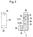
- FIG. 3 shows in a schematic sectional view of a part of rotationally symmetrical collar area of a Hollow castings (left) and the part of the mold 3, the the outer shape of the collar area shown shaped (right).
- the representation in FIG. 3 corresponds essentially to a section of the lower right corner of Fig. 1.
- the wall thickness of the mold 3 with the Reference number DK denotes and that for cooling essential material volume of the mold 3 with the VK.
- for cooling essential material volume are the Volume areas of the mold wall meant that immediately be limited by the shaping surface 9.
- the collar area shown in the left part of FIG. 3 of the hollow casting has a total volume that with VG is designated, as well as a wall thickness that with DG is designated.
- the heat can be dissipated through the surface OG of the Collar area are given off, the heat both by the left part of the surface OG in FIG the sand core 21 flows as well through the lower and right part of the upper floor into the mold 3.
- the the surface of the heat-emitting surface is the same as large as those surfaces of the mold 1 that the of limit the area of the casting space 5 surrounding the mold.
- the method according to the invention can be Cylinder liners for reciprocating piston internal combustion engines, especially for large diesel engines, especially due to the optimized time and spatial solidification course of the casting compound 6, very much good mechanical properties, e.g. B. high strength and have high elongation, so that such Cylinder liners also for use in modern, powerful machines are suitable.
Abstract
Description
Die Erfindung betrifft eine Giessform und ein Verfahren zum Herstellen von metallischen Hohlgiesslingen gemäss dem Oberbegriff des jeweiligen unabhängigen Anspruchs sowie einen mittels dieser Giessform bzw. dieses Verfahrens hergestellten Hohlgiessling mit zwei Bereichen unterschiedlicher Wandstärke. Im speziellen betrifft die Erfindung eine Giessform und ein Verfahren zum Herstellen von Zylinderlaufbuchsen für Hubkolbenbrennkraftmaschinen, insbesondere für Grossdieselmotoren.The invention relates to a casting mold and a method for the manufacture of hollow metal castings according to the preamble of the respective independent claim and one using this mold or this Process produced hollow casting with two areas different wall thickness. In particular, the Invention a mold and a method for manufacturing of cylinder liners for reciprocating internal combustion engines, especially for large diesel engines.
In Hubkolbenbrennkraftmaschinen, insbesondere in Grossdieselmotoren, wie sie beispielsweise im Schiffbau verwendet werden, unterliegen die Zylinderlaufbuchsen im Betriebszustand einer extrem starken mechanischen und thermischen Belastung. Besonders im Explosionsbereich des Brennstoffgemischs ist die Zylinderlaufbuchse hohen Drücken und hohen Temperaturen ausgesetzt. Deshalb muss die Zylinderlaufbuchse insbesondere im Explosionsbereich eine hohe Festigkeit aufweisen, um den bei der Explosion des Brennstoffgemischs entstehenden Spannungen standzuhalten.In reciprocating internal combustion engines, especially in Large diesel engines, such as those used in shipbuilding are used, the cylinder liners are subject to Operating condition of an extremely strong mechanical and thermal load. Especially in the explosion area of the Fuel mixture is high in the cylinder liner Pressures and high temperatures. Therefore must the cylinder liner especially in the explosion area have a high strength to withstand the explosion of the fuel mixture to withstand.
Um die Festigkeit der Zylinderlaufbuchsen in dem Bereich zu erhöhen, in dem im Betriebszustand die Explosion des Brennstoffgemisches stattfindet, werden die Zylinderlaufbuchsen üblicherweise in diesen Bereichen dickwandiger ausgestaltet. Das heisst eine solche Zylinderlaufbuchse weist im wesentlichen zwei Bereiche mit deutlich unterschiedlicher Wandstärke auf: einen ersten Bereich, in welchem die Wandstärke grösser ist und welcher der üblichen Nomenklatur folgend als Kragenbereich bezeichnet wird, sowie einen zweiten Bereich, in welchem die Wandstärke kleiner ist und welcher als Hemdbereich bezeichnet wird.To the strength of the cylinder liners in the area to increase, in which the explosion of the Fuel mixture takes place, the Cylinder liners are typically used in these areas thick-walled. That means one The cylinder liner has two main areas with significantly different wall thickness: one first area in which the wall thickness is greater and which according to the usual nomenclature as Collar area is referred to as well as a second Area in which the wall thickness is smaller and which is called the shirt area.
Häufig werden Zylinderlaufbuchsen für Brennkraftmaschinen mittels Giessverfahren aus Gusseisen und speziell aus Grauguss-Legierungen hergestellt. Neben der chemischen Zusammensetzung der als Giessmasse verwendeten Legierung werden die physikalischen und metallurgischen Eigenschaften der Zylinderlaufbuchse, wie beispielsweise Gefügestruktur, Festigkeit, Dehnung, tribologische Eigenschaften, auch von dem Erstarrungsverlauf der Giessmasse ganz wesentlich beeinflusst. Deshalb ist die verwendete Giessform bzw. das durchgeführte Giessverfahren von grosser Bedeutung für die Eigenschaften der Zylinderlaufbuchse.Cylinder liners for internal combustion engines are often used by means of casting processes from cast iron and especially from Made of gray cast iron alloys. In addition to the chemical Composition of the alloy used as casting compound become the physical and metallurgical Properties of the cylinder liner, such as Structure, strength, elongation, tribological Properties, also from the solidification process of the Casting material significantly influenced. That is why used mold or the carried out Casting process of great importance for the Properties of the cylinder liner.
Für die Herstellung von Zylinderlaufbuchsen sind vom Stand der Technik zwei unterschiedliche Arten von Giessverfahren bekannt. Bei den Sandgiessverfahren wird die flüssige Giessmasse in eine Sandform eingefüllt, die zuvor entsprechend der gewünschten Gestalt des herzustellenden Giesslings, gegebenenfalls unter Berücksichtigung einer Bearbeitungszugabe, modelliert wurde. Eine solche Sandform wird aus mit einem Bindemittel versetztem Quarzsand bzw. einem anderen, sandähnlichen Mineralstoff z. B. durch chemische oder thermische Aushärtung erstellt und ist üblicherweise nur für den Einmalgebrauch ausgelegt. Nachteilig an solcherart hergestellten Zylinderlaufbuchsen ist jedoch, dass sie beispielsweise bezüglich ihrer Gefügestruktur, ihrer Festigkeit und ihrer Dehnung immer weniger den Anforderungen genügen, wie sie in modernen Hubkolbenbrennkraftmaschinen, insbesondere mit grosser Leistung, gestellt werden. Dies ist hauptsächlich darauf zurückzuführen, dass der Erstarrungsverlauf der Giessmasse, insbesondere die Erstarrungszeit, in der Sandform unter metallurgischen Aspekten nicht optimal ist.For the manufacture of cylinder liners are from State of the art two different types of Casting process known. In the sand casting process the liquid casting compound is poured into a sand mold, the beforehand according to the desired shape of the castings to be produced, if necessary under Consideration of a machining allowance, modeled has been. Such a sand mold is made with one Binder quartz sand or another, sand-like mineral z. B. by chemical or thermal curing created and is usually only designed for single use. Disadvantageous cylinder liners produced in this way is, however, that, for example, in terms of their structure, their strength and their stretch less and less The requirements are sufficient, as they are in modern Reciprocating internal combustion engines, especially with large ones Performance. This is mainly due to it attributed that the solidification process of the Casting compound, especially the setting time, in the Sand form not optimal under metallurgical aspects is.
Bei der zweiten Art von Giessverfahren, den sogenannten Kokillengiessverfahren, verwendet man eine meist aus Gusseisen hergestellte Giessform (Kokille), in welche die flüssige Giessmasse eingefüllt wird. Die äussere Gestalt erhält der Giesslings hier also durch eine metallische Form, in der die Giessmasse erstarrt. Solche Kokillen können üblicherweise mehrfach gebraucht werden. Bei Kokillengiessverfahren unterliegt die äussere Gestalt des hergestellten Giesslings jedoch relativ starken geometrischen Einschränkungen, weil die Kokille nach dem Erstarren bzw. nach dem Abkühlen des Giesslings von diesem abziehbar sein muss. Aufgrund dieser Randbedingung können geometrische Details in der äusseren Gestalt des Giesslings normalerweise bei Kokillengiessverfahren nicht mit vertretbarem Aufwand geformt werden. Deshalb muss man bei der Herstellung z. B. von Zylinderlaufbuchsen den Giessling mit relativ grossen Bearbeitungszugaben herstellen, um anschliessend die gewünschte äussere Gestalt der Zylinderlaufbuchse realisieren zu können, das heisst der Giessling weicht bezüglich seiner äusseren Gestalt in der Regel noch recht stark von dem gewünschten Endprodukt ab. Dies bedingt zeit- und kostenintensive Nachbearbeitungen, bei denen grosse Materialmengen z. B. mittels spanender Arbeitsverfahren entfernt werden müssen. Solche grossen Bearbeitungszugaben bedingen einen deutlich erhöhten Bedarf an Giessmasse und sind auch deshalb unter wirtschaftlichen Aspekten nicht wünschenswert.In the second type of casting process, the so-called Chill casting process, one is mostly used Cast iron mold (mold) into which the liquid casting compound is filled. The outer shape the castings get here by a metallic Form in which the casting compound solidifies. Such molds can usually be used several times. At Chill casting is subject to the outer shape of the produced castings, however, relatively strong geometrical restrictions because the mold after the Solidify or after the casting has cooled down must be removable. Because of this constraint can geometric details in the outer shape of the Giesslings usually do not with permanent mold casting processes be formed with reasonable effort. So you have to in the manufacture of e.g. B. of cylinder liners Giessling with relatively large processing allowances to create the desired exterior To be able to realize the shape of the cylinder liner, that is called the castling gives way to its outer Usually shape quite strongly from the desired one End product. This is time-consuming and costly Postprocessing in which large amounts of material e.g. B. can be removed by machining processes have to. Such large processing allowances require one significantly increased need for casting compound and are also therefore not in economic terms desirable.
Insbesondere bei der Herstellung von sehr grossen Giesslingen wie z. B. Zylinderlaufbuchsen für moderne leistungsstarke Grossmotoren, resultieren auch aus dem Gewicht der Kokille Probleme. Eine solche mit Giessmasse gefüllte Kokille hat beispielsweise ein Gewicht im Bereich von einigen zehn Tonnen. Viele Giessereien verfügen nicht über genügend starke Hebevorrichtungen, um solche Massen zu bewegen, z. B. um eine gefüllte Kokille zum Abkühlen an einen anderen Platz zu transportieren, oder um die Kokille von dem Giessling abzuziehen. Es wären umfangreiche und sehr kostenintensive Umrüstarbeiten vonnöten, um genügend starke Hebevorrichtungen zu installieren.Especially in the production of very large ones Castings such as B. cylinder liners for modern powerful large motors also result from the Weight of the mold problems. One with casting compound filled mold has a weight in the Range of several tens of tons. Many foundries do not have enough strong lifting devices to to move such masses, e.g. B. a filled mold to move to another place to cool down, or to pull the mold off the casting. It would be extensive and very costly Conversion work required to be strong enough Install lifting devices.
Ausgehend von diesem Stand der Technik ist es eine Aufgabe der Erfindung, eine Giessform und ein Verfahren zum Herstellen von metallischen Hohlgiesslingen bereitzustellen, welche einen möglichst optimalen räumlichen und zeitlichen Erstarrungsverlauf in der Giessmasse ermöglichen und gleichzeitig mit relativ kleinen Bearbeitungszugaben auskommen. Im speziellen ist es eine Aufgabe der Erfindung, eine Giessform und ein Verfahren bereitzustellen, welche mit relativ geringen Bearbeitungszugaben die Herstellung solcher Zylinderlaufbuchsen für Hubkolbenbrennkraftmaschinen, insbesondere für Grossdieselmotoren, ermöglichen, die hinsichtlich ihrer Belastbarkeit (z. B. Festigkeit, Dehnung) auch den Anforderungen in modernen leistungsstarken Maschinen genügen.Based on this state of the art, it is one Object of the invention, a casting mold and a method for the production of hollow metal castings to provide the most optimal spatial and temporal solidification in the Allow casting compound and at the same time with relative small processing allowances. In particular is it is an object of the invention, a mold and a To provide methods that are relatively low Machining allowances the manufacture of such Cylinder liners for reciprocating piston internal combustion engines, especially for large diesel engines, enable the with regard to their resilience (e.g. strength, Elongation) also meet the requirements in modern powerful machines are sufficient.
Die diese Aufgaben in apparativer und verfahrenstechnischer Hinsicht lösenden Gegenstände der Erfindung sind durch die Merkmale des jeweiligen unabhängigen Anspruchs gekennzeichnet. Die erfindungsgemässe Giessform zum Herstellen von metallischen Hohlgiesslingen aus einer Giessmasse, insbesondere zum Herstellen von Zylinderlaufbuchsen für Hubkolbenbrennkraftmaschinen, speziell für Grossdieselmotoren, hat einem Einlass zum Einbringen der Giessmasse in einen Giessraum, welcher durch Formgebungsflächen begrenzt ist und die Giessmasse aufnimmt. Die erfindungsgemässe Giessform umfasst eine Kokille und eine Sandform, wobei die Kokille eine erste Formgebungsfläche aufweist, und die Sandform die übrigen massgebenden Formgebungsflächen.These tasks in apparatus and procedurally resolved objects of Invention are characterized by the characteristics of each characterized independent claim. The Casting mold according to the invention for producing metallic hollow castings from a casting compound, especially for the manufacture of cylinder liners for Reciprocating internal combustion engines, especially for Large diesel engines, has an inlet for the introduction of the Pouring compound into a casting room, which through Forming surfaces are limited and the casting compound records. The casting mold according to the invention comprises a Mold and a sand mold, the mold being a first Has shaping surface, and the sand mold the rest decisive shaping surfaces.
Überraschenderweise zeigt sich, dass die erfindungsgemässe Giessform und das erfindungsgemässe Verfahren die jeweiligen Vorteile sowohl des Sandgiessverfahrens als auch des Kokillengiessverfahrens aufweisen, ohne dass die vorne erwähnten Nachteile in Kauf genommen werden müssen. Durch die erfindungsgemässe Kombination der Kokille mit der Sandform lässt sich - wie weiter hinten detaillierter erläutert - der räumliche und zeitliche Erstarrungsverlauf in der Giessmasse so optimieren, dass die mechanische Belastbarkeit des Hohlgiesslings (z. B. seine Festigkeit und Härte) deutlich grösser ist, als bei Giesslingen, die beispielsweise mit konventionellen Sandgiessverfahren bzw. Sandformen hergestellt werden. Gleichzeitig ermöglicht die Sandform der erfindungsgemässen Giessform, bzw. ihre Verwendung bei dem erfindungsgemässen Verfahren, eine hohe Flexibilität bezüglich der äusseren Gestalt des von ihr geformten Bereichs des Hohlgiesslings, so dass nur vergleichsweise kleine Bearbeitungszugaben vonnöten sind. Surprisingly, it turns out that the Casting mold according to the invention and the inventive Procedure the respective advantages of both Sand casting process as well as the permanent mold casting process without the disadvantages mentioned above in Purchase must be made. By the inventive Combination of the mold with the sand mold can - how explained in more detail below - the spatial and solidification over time in the casting compound optimize that the mechanical strength of the Hollow castings (e.g. its strength and hardness) is significantly larger than that of Giesslingen, which for example with conventional sand casting processes or sand molds are produced. At the same time enables the sand mold of the casting mold according to the invention, or their use in the inventive Process, high flexibility with regard to the exterior Shape of the area of the shape that it forms Hollow castings, so that only comparatively small Machining allowances are required.
Vorzugsweise ist die Kokille der erfindungsgemässen Giessform einstückig ausgestaltet, weil sich hierdurch thermisch bedingte Schädigungen des Hohlgiesslings, wie sie an der Grenzfläche zwischen zwei aneinanderstossenden Kokillenteilen auftreten können, vermeiden lassen.The mold is preferably the one according to the invention Cast mold designed in one piece because of this thermal damage to the hollow casting, such as they at the interface between two butts Mold parts can occur, have them avoided.
Bevorzugt weist die die Kokille Leitungen für ein fluides Medium, insbesondere Luft, zum Ab- und/oder Zuführen von Wärme auf. Diese Massnahme ist vorteilhaft, weil die Kokille vor dem Einbringen der flüssigen Giessmasse in einfacher Weise, nämlich z. B. indem warme Luft durch die Leitungen geblasen wird, vorgewärmt werden kann. Zusätzlich kann die heisse Kokille nach dem Entfernen des Hohlgiesslings einfach und rasch, z. B. mittels Kaltluft, gekühlt werden und steht so nach kurzer Zeit wieder für einen neuen Giessvorgang zur Verfügung. Auch besteht die vorteilhafte Möglichkeit, während und/oder nach dem Einbringen der Giessmasse der Kokille Wärme zu entziehen.The mold preferably has lines for a fluid Medium, especially air, for the removal and / or supply of Heat up. This measure is advantageous because the Mold before introducing the liquid casting compound into simple way, namely z. B. by warm air through the Blown lines can be preheated. In addition, the hot mold can be removed after removing the Hollow castings easily and quickly, e.g. B. using cold air, can be cooled and stands for again after a short time a new casting process is available. It also exists advantageous possibility during and / or after Introduce the casting compound to withdraw heat from the mold.
In einer bevorzugten Ausgestaltung umfasst die Sandform einen Sandkern und einen Sandmantel, wobei der Giessraum von dem Sandkern einerseits und dem Sandmantel sowie der Kokille andererseits begrenzt ist.In a preferred embodiment, the sand mold comprises a sand core and a sand coat, the casting room of the sand core on the one hand and the sand coat and the On the other hand, mold is limited.
Die Kokille ist vorzugsweise ein einseitig offenes Gefäss mit einer inneren Wandung und einem Boden, wobei die innere Wandung und zumindest ein Teil des Bodens die erste Formgebungsfläche bilden. Durch diese Massnahme entsteht eine möglichst grösse Kontaktfläche zwischen der Kokille und der Giessmasse, wodurch sich die Wärmeübertragung zwischen Giessmasse und Kokille verbessert, insbesondere beschleunigt.The mold is preferably a vessel that is open on one side with an inner wall and a bottom, the inner wall and at least part of the floor form the first shaping surface. Through this measure the largest possible contact area between the Chill mold and the casting compound, whereby the Heat transfer between the casting compound and the mold improved, especially accelerated.
Auch ist es vorteilhaft, wenn der Boden des Kokillenelements eine Ausnehmung aufweist und sich der Sandkern bis in diese Ausnehmung hinein erstreckt. It is also advantageous if the bottom of the Mold element has a recess and the Sand core extends into this recess.
Dadurch lässt sich der Sandkern in einfacher Weise bezüglich des Sandmantels und der Kokille zentrieren, wodurch die Radialsymmetrie des Hohlgiesslings gewährleistet ist.This allows the sand core to be easily removed center with respect to the sand shell and the mold, whereby the radial symmetry of the hollow casting is guaranteed.
Insbesondere für die Herstellung von Zylinderlaufbuchsen ist es vorteilhaft, wenn die Giessform so ausgestaltet ist, dass der Abstand zwischen dem Sandkern und der inneren Wandung der Kokille grösser ist als der Abstand zwischen dem Sandkern und dem Sandmantel. Dadurch wird der dickwandigere Bereich des Hohlgiesslings, also der Bereich, der dem Kragenbereich der Zylinderlaufbuchse entspricht, in der Kokille geformt. Dies ist besonders günstig für den Erstarrungsverlauf des Hohlgiesslings weil der dickwandige Bereich (Kragenbereich) durch die Kokille mindestens gleich schnell, aber auch schneller, zur Erstarrung gebracht werden kann wie der dünnwandige Bereich (Hemdbereich), der von der Sandform geformt wird.Especially for the production of cylinder liners it is advantageous if the mold is designed in this way is that the distance between the sand core and the inner wall of the mold is larger than the distance between the sand core and the sandcoat. This will the thick-walled area of the hollow casting, that is Area corresponding to the collar area of the cylinder liner corresponds, molded in the mold. This is special favorable for the solidification process of the hollow casting because the thick-walled area (collar area) through the Chill mold at least as fast, but also faster, can freeze like the thin-walled Area (shirt area) that is shaped by the sand mold.
Vor allem im Hinblick auf einen möglichst optimalen räumlichen und zeitlichen Erstarrungsverlauf ist es vorteilhaft, die Ausgestaltung der Kokille an denjenigen Bereich der Giessform anzupassen, der von der Kokille umgeben ist. Dies bedeutet insbesondere für die Herstellung von Zylinderlaufbuchsen, dass bei der Ausgestaltung der Kokille die Abmessungen des Kragenbereichs des Hohlgiesslings berücksichtigt werden. Deshalb werden folgende Massnahmen bevorzugt getroffen:
- die erste Formgebungsfläche bildet etwa die Hälfte derjenigen Flächen der Giessform, welche den Giessraum in dem Bereich begrenzen, der von der Kokille umgeben ist. Hieraus resultiert eine grosse Kontaktfläche, durch welche die Wärme aus der Giessmasse in die Kokille fliessen kann.
- das für die Kühlung des Hohlgiesslings wesentliche Materialvolumen der Kokille ist mindestens doppelt so gross ist wie das Volumen des von der Kokille umgebenen Bereichs des Giessraums. Somit ist gewährleistet, dass die Wärmekapazität der Kokille ausreichend ist, um eine rasche Erstarrung im Kragenbereich zu ermöglichen.
- die Wanddicke der Kokille beträgt weniger als das 1.5-fache, insbesondere etwa das 0.9-fache, des Abstands zwischen dem Sandkern und der inneren Wandung der Kokille.
- the first shaping surface forms approximately half of those surfaces of the casting mold which delimit the casting space in the area which is surrounded by the mold. This results in a large contact area through which the heat can flow from the casting compound into the mold.
- the material volume of the mold which is essential for cooling the hollow casting is at least twice as large as the volume of the area of the casting space which is surrounded by the mold. This ensures that the heat capacity of the mold is sufficient to allow rapid solidification in the collar area.
- the wall thickness of the mold is less than 1.5 times, in particular approximately 0.9 times, the distance between the sand core and the inner wall of the mold.
Das erfindungsgemässe Verfahren dient zum Herstellen von metallischen Hohlgiesslingen, insbesondere Zylinderlaufbuchsen für Hubkolbenbrennkraftmaschinen, speziell für Grossdieselmotoren, wobei die Hohlgiesslinge einen ersten und einen zweiten Bereich aufweisen und die Wandstärke des Hohlgiesslings im ersten Bereich grösser ist als im zweiten Bereich. Bei dem erfindungsgemässen Verfahren wird eine Giessmasse in eine Giessform eingebracht und erstarrt dort. Gemäss der Erfindung wird die äussere Gestalt des Hohlgiesslings im ersten Bereich durch eine Kokille und im zweiten Bereich durch eine Sandform geformt.The method according to the invention is used to manufacture metallic hollow castings, in particular Cylinder liners for reciprocating piston internal combustion engines, especially for large diesel engines, whereby the hollow castings have a first and a second region and the The wall thickness of the hollow casting is larger in the first area is as in the second area. In the inventive The process is a casting compound in a mold introduced and solidifies there. According to the invention the outer shape of the hollow casting in the first area by a mold and in the second area by a Shaped sand mold.
Aus bereits vorne im Zusammenhang mit der erfindungsgemässen Giessform genannten Gründen ist es auch für das erfindungsgemässe Verfahren von Vorteil,
- wenn zum Formen der äusseren Gestalt des Hohlgiesslings im ersten Bereich eine einstückige Kokille verwendet wird;
- wenn die Kokille vor dem Einbringen der Giessmasse durch ein fluides Medium, insbesondere Luft, erwärmt wird;
- wenn die Kokille während und/oder nach dem Einbringen der Giessmasse durch einen fluides Medium, insbesondere Luft, gekühlt wird.
- if a one-piece mold is used to form the outer shape of the hollow casting in the first region;
- if the mold is heated by a fluid medium, in particular air, before the casting compound is introduced;
- if the mold is cooled by a fluid medium, in particular air, during and / or after the casting compound has been introduced.
Die erfindungsgemässe Giessform bzw. das erfindungsgemässe Verfahren eignen sich insbesondere für die Herstellung von Zylinderlaufbuchsen für eine Hubkolbenbrennkraftmaschine, speziell für einen Grossdieselmotor, mit zwei Bereichen unterschiedlicher Wandstärke.The mold according to the invention or the Methods according to the invention are particularly suitable for the production of cylinder liners for a Reciprocating internal combustion engine, especially for one Large diesel engine, with two areas different Wall thickness.
Die erfindungsgemässe Giessform ist insbesondere für die Durchführung des erfindungsgemässen Verfahrens geeignet.The mold according to the invention is particularly suitable for Suitable for carrying out the method according to the invention.
Weitere vorteilhafte Massnahmen und bevorzugte Verfahrensausgestaltungen ergeben sich aus den abhängigen Ansprüchen.Other advantageous measures and preferred Process configurations result from the dependent Claims.
Im folgenden wird die Erfindung sowohl in Bezug auf die verfahrenstechnischen als auch in Bezug auf die apparativen Aspekte anhand der Zeichnung näher erläutert. In der schematischen nicht massstäblichen Zeichnung zeigen:
- Fig. 1
- einen Schnitt durch ein Ausführungsbeispiel der erfindungsgemässen Giessform im gefüllten Zustand,
- Fig.2
- einen Schnitt durch eine Variante für die Kokille des Ausführungsbeispiels aus Fig. 1, und
- Fig. 3
- eine schematische Schnittdarstellung eines Teils einer Zylinderlaufbuchse und eines Teils einer Kokille.
- Fig. 1
- 3 shows a section through an exemplary embodiment of the casting mold according to the invention in the filled state,
- Fig. 2
- a section through a variant for the mold of the embodiment of Fig. 1, and
- Fig. 3
- is a schematic sectional view of part of a cylinder liner and part of a mold.
In der Zeichnung sind gleiche oder von der Funktion her gleichwertige Teile mit den gleichen Bezugszeichen versehen.In the drawing, the same or in terms of function equivalent parts with the same reference numerals Mistake.
Die folgenden Erläuterungen der Erfindung anhand eines Ausführungsbeispiels der erfindungsgemässen Giessform zum Herstellen von metallischen Hohlgiesslingen aus einer Giessmassse dienen in sinngemäss gleicher Weise auch als Beschreibung eines Ausführungsbeispiels des erfindungsgemässen Verfahrens zum Herstellen von metallischen Hohlgiesslingen, die einen ersten und einen zweiten Bereich aufweisen, wobei die Wandstärke des Hohlgiesslings im ersten Bereich grösser ist als im zweiten Bereich.The following explanations of the invention using a Embodiment of the mold according to the invention for Manufacture of metallic hollow castings from one Casting compounds serve in the same way as Description of an embodiment of the inventive method for producing metallic hollow castings, the first and one have second area, the wall thickness of the Hollow castings in the first area is larger than in second area.
Ferner beziehen sich die folgenden Erläuterungen mit beispielhaftem Charakter nur auf die Herstellung von Zylinderlaufbuchsen für Hubkolbenbrennkraftmaschinen, insbesondere für Grossdieselmotoren. Sie gelten jedoch sinngemäss auch für die Herstellung anderer metallischer Hohlgiesslinge. Mit dem Begriff "Hohlgiesslinge" sind solche Giesskörper gemeint, die neben ihrer äusseren Begrenzungsfläche zumindest eine Begrenzungsfläche aufweisen, die dem Körperinneren zugewandt ist, also z. B. hohlzylinderförmige Körper, Buchsen ganz allgemein, oder rohrartige Gebilde.The following explanations also apply exemplary character only on the production of Cylinder liners for reciprocating piston internal combustion engines, especially for large diesel engines. However, they apply analogously also for the production of other metallic Hollow castings. With the term "hollow castings" are such casting body meant that next to their outer Boundary surface at least one boundary surface have, which faces the inside of the body, so e.g. B. hollow cylindrical body, bushings in general, or tubular structures.
Es ist heute üblich, insbesondere für Grossdieselmotoren solche Zylinderlaufbuchsen zu verwenden, die einen ersten Bereich, den sogenannten Kragenbereich und einen zweiten Bereich, den sogenannten Hemdbereich, aufweisen, wobei die mittlere Wandstärke der Zylinderlaufbuchse im Kragenbereich deutlich grösser ist als im Hemdbereich, beispielsweise mindestens doppelt so gross. Der Kragenbereich ist derjenige, in dem im Betriebszustand des Motors die Explosion des Brennstoffgemischs stattfindet, der also den höchsten Drücken und Temperaturen und somit der höchsten Belastung ausgesetzt ist. Um dieser Belastung standzuhalten, ist der Kragenbereich normalerweise mit einer grösseren Wandstärke ausgestaltet.It is common today, especially for large diesel engines to use such cylinder liners, the first Area, the so-called collar area and a second Have area, the so-called shirt area, where the average wall thickness of the cylinder liner in Collar area is significantly larger than in the shirt area, for example at least twice as large. Of the Collar area is the one in the operating state explosion of the fuel mixture of the engine takes place, which is the highest pressures and Exposed to temperatures and thus the highest stress is. To withstand this burden, is the Collar area usually with a larger one Wall thickness designed.
Fig. 1 zeigt in einer Schnittdarstellung ein bevorzugtes
Ausführungsbeispiel der erfindungsgemässen Giessform,
welche gesamthaft mit dem Bezugszeichen 1 versehen ist.
Die Giessform 1 hat einen Einlass 4 zum Einbringen einer
Giessmasse 6 in einen Giessraum 5. Der Giessraum 5 ist
durch Formgebungsflächen 7, 8, 9 begrenzt. Mit dem
Begriff "Formgebungsflächen" werden solche körperlich
vorhandenen Flächen bezeichnet, die einen wesentlichen
Einfluss auf die Gestalt des Hohlgiesslings haben, das
heisst die Gesamtheit der Formgebungsflächen 7,8,9 ist
massgebend für die Gestalt des Hohlgiesslings, sie formt
ihn also. Im wesentlichen stimmen die Formgebungsflächen
7,8,9 mit den Kontaktflächen zwischen Giessmasse 6 und
Giessform 1 überein.Fig. 1 shows a preferred in a sectional view
Embodiment of the casting mold according to the invention,
which is generally provided with the
Fig. 1 zeigt die Giessform 1 in gefülltem Zustand, d.h.
die Giessmasse 6 befindet sich im Giessraum 5 und füllt
diesen aus. Zum besseren Verständnis ist in Fig. 1 die
Giessmasse 6 zweiteilig mit unterschiedlichen Schraffuren
dargestellt. Der grössere, mit dem Bezugszeichen 6a
versehene Teil deutet dabei die fertige
Zylinderlaufbuchse an, also die Form des Endprodukts. Der
kleinere, mit dem Bezugzeichen 6b versehene Teil deutet
die Bearbeitungszugabe an. Natürlich ist diese
zweiteilige Darstellung der Giessmasse 6 symbolisch zu
verstehen.Fig. 1 shows the
Erfindungsgemäss umfasst die Giessform 1 eine Kokille 3
und eine Sandform 2, wobei die Kokille 3 eine erste
Formgebungsfläche 9 aufweist und die Sandform 2 die
übrigen massgebenden Formgebungsflächen 7, 8.According to the invention, the casting
Bei dem in Fig. 1 gezeigten Ausführungsbeispiel ist die
Kokille 3 ein einstückiges, einseitig offenes Gefäss mit
einer inneren Wandung 31 und einem Boden 32 (siehe auch
Fig. 2). Die innere Wandung 31 bildet zusammen mit einem
Teil 32a des Bodens 32 die erste Formgebungsfläche 9. Im
Boden 32 der Kokille 3 ist eine Ausnehmung 322 (siehe
Fig. 2) vorgesehen, deren Funktion weiter hinten
erläutert wird. Ferner weist die Kokille 3 Leitungen 33
für ein fluides Medium, vorzugsweise Luft, auf. Diese
Leitungen 33 können Kanäle im Innern der Kokillenwand
sein oder Rohrleitungen, die in das Innere der
Kokillenwand eingegossen sind. Durch diese Leitungen 33
kann Luft geblasen werden, um der Kokille 3 Wärme
zuzuführen oder zu entziehen. Ferner ist die Kokille 3 an
ihrer Aussenwand mit Tragevorrichtungen 34 versehen, an
denen sie angehoben werden kann. Die Kokille 3 ist z. B.
in an sich bekannter Weise aus Gusseisen hergestellt.In the embodiment shown in Fig. 1 is the
Die Sandform 2 des in Fig. 1 dargestellten
Ausführungsbeispiels umfasst einen Sandkern 21 sowie
einen Sandmantel 22. Der Sandkern 21 erstreckt sich bis
in die Ausnehmung 322 im Boden 32 der Kokille 3. Seine
Mantelfläche bildet die Formgebungsfläche 7. Der
Sandmantel 22 weist im wesentlichen die Form eines
Hohlzylinders oder eines hohlen Kegelstumpfs auf und
umgibt den Sandkern 21 im wesentlichen konzentrisch. Die
dem Sandkern 21 zugewandte Begrenzungsfläche des
Sandmantels 22 bildet die Formgebungsfläche 8. Je nach
der äusseren Gestalt des herzustellenden Hohlgiesslings
kann der Sandmantel 22 einstückig sein oder - wie in
Fig. 1 dargestellt - aus mehreren Formkästen 22a,22b,22c
zusammengesetzt sein. Die Herstellung der Sandform 22 an
sich kann in analoger Weise erfolgen wie dies von
konventionellen Sandgiessverfahren hinreichend bekannt
ist und bedarf daher keiner näheren Erläuterung. Der
Sandmantel 22 ist dichtend aber lösbar mit der Kokille 3
verbunden. Durch bekannte Dichtmittel lässt sich ein
Austreten der flüssigen Giessmasse 6 zwischen der Kokille
3 und dem Sandmantel 22 unterbinden.The
Somit ist der Giessraum 5 einerseits von dem Sandkern 21
bzw. der Formgebungsfläche 7 begrenzt und andererseits
von dem Sandmantel 22 und der Kokille 3 bzw. den
zugehörigen Formgebungsflächen 8 und 9, das heisst die
äussere Gestalt des Hohlgiesslings wird im wesentlichen
durch die erste Formgebungsfläche 9 der Kokille 3 und die
Formgebungsfläche 8 des Sandmantels 22 bestimmt.The casting space 5 is thus on the one hand from the
Bei dem in Fig. 1 dargestellten bevorzugten
Ausführungsbeispiel ist in die Ausnehmung 322 im Boden 32
der Kokille 3 ein weiteres Sandelement 10 eingepasst,
welches ein Ende des Sandkerns 21 bündig aufnimmt. Dabei
ist das Sandelement 10, das in gleicher Weise herstellbar
ist wie konventionelle Sandformen, derart geformt, dass
es den Sankern 21 bezüglich der Kokille 3 zentriert.
Durch diese Massnahme ist die Radialsymmetrie des
Hohlgiesslings realisierbar.In the preferred shown in Fig. 1
The exemplary embodiment is in the
Die äussere Gestalt des Hohlgiesslings im ersten Bereich,
also demjenigen Bereich, der die grössere Wandstärke
aufweist (Kragenbereich), wird durch die Kokille 3
geformt. Deshalb ist bei der in Fig. 1 dargestellten
Giessform 1 der Abstand zwischen dem Sandkern 21 und der
inneren Wandung 31 der Kokille 3 grösser als der Abstand
zwischen dem Sandkern 21 und dem Sandmantel 22. Ferner
ist das Ausführungsbeispiel der Giessform 1 für
steigenden Guss ausgestaltet, das heisst die flüssige
Giessmasse 6 wird am unteren Ende der Giessform 1 in den
Giessraum 5 eingebracht. Hierzu umfasst der Einlass 4
einen Einlasskanal 41, der sich etwa im Zentrum des
Sandkerns 21 durch diesen und entlang seiner Längsachse
erstreckt. Der Einlasskanal 41 mündet in einen Verteiler
42, der sich in dem Sandelement 10 in der Ausnehmung 322
befindet. Der Verteiler 42 verbindet den Einlasskanal 41
mit dem Giessraum 5, so dass die flüssige Giessmasse 6
durch den Einlasskanal 41 und den Verteiler 42 an das
untere Ende des Giessraums 5 gelangt. Am oberen Ende
(gemäss der Darstellung in Fig. 1) des Giessraums 5 sind
Überlaufbehälter 11 vorgesehen, die sich ebenfalls mit
Giessmasse 6 füllen, wenn der Giessraum 5 gefüllt ist.
Die Überlaufbehälter 11 dienen gleichzeitig als
Ausgleichsbehälter, aus denen die Giessmasse 6 in den
Giessraum 5 zurückfliessen kann, wenn das Volumen der
Giessmasse 6 im Giessraum 5 bei der Erstarrung abnimmt.The outer shape of the hollow casting in the first area,
that is, the area with the greater wall thickness
has (collar area), the
Es versteht sich, dass die erfindungsgemässe Giessform
bzw. das erfindungsgemässe Verfahren auch für fallenden
Guss ausgelegt sein können, d. h. der Giessraum 5 wird
dann von oben (gemäss der Darstellung in Fig. 1) mit der
Giessmasse 6 befüllt. Dies kann beispielsweise mittels
eines Ringspeisers erfolgen, der auf das obere Ende der
Giessform 1 aufgesetzt wird.It is understood that the mold according to the invention
or the method according to the invention also for falling
Cast can be designed, d. H. the casting room 5
then from above (as shown in Fig. 1) with the
Casting compound 6 filled. This can be done using, for example
a ring feeder, which is on the upper end of the
Fig. 2 zeigt einen Schnitt durch eine Variante für die
Kokille 3. Die meisten der Bezugszeichen in Fig. 2 sind
bereits weiter vorne erläutert. Diese Erläuterungen
sollen durch Fig. 2 nochmals verdeutlicht werden. Ein
Unterschied bei der in Fig. 2 dargestellten Variante der
Kokille 3 liegt darin, dass die innere Wandung 31 nicht
glattwandig ausgestaltet ist, sondern einen Absatz 311
aufweist. Hierdurch ist es möglich, die Form des
Hohlgiesslings noch mehr der gewünschtewn Form des
Endprodukt anzugleichen und somit die notwendige
Nachbearbeitung weiter zu reduzieren. Bei der Variante
der Kokille 3 gemäss Fig. 2 sind in der Wand der Kokille
3 zwei getrennte Leitungen 331 und 332 für das fluide
Medium zum Ab- und Zuführen von Wärme vorgesehen. Jede
der Leitungen 331 und 332 ist als Rohrleitung
ausgestaltet, die in die Wand der Kokille 3 eingegossen
ist und die Kokille 3 zweimal in Umfangsrichtung umläuft.
Von einer ersten Öffnung 331a bzw. 332a erstreckt sich
die jeweils zugehörige Rohrleitung im Innern der
Kokillenwand parallel zum Umfang um die Kokille 3 herum,
führt dann in der Wand nach oben, umläuft nochmals die
Kokille 3 in Umfangsrichtung und endet an einer zweiten
Öffnung 331b bzw. 332b. Durch jede dieser Leitungen 331
und 332 kann das fluide Medium, vorzugsweise Luft, bewegt
werden, um der Kokille Wärme zuzuführen oder zu
entziehen. Somit ist es beispielsweise mittels Warmluft
möglich, die Kokille 3 in einfacher Weise vorzuwärmen, um
thermisch bedingte Schädigungen bei dem Kontakt mit der
heissen Giessmasse 6 zu vermeiden. Es hat sich als
günstig erwiesen, die Kokille 3 vor dem Einbringen der
Giessmasse 6 auf eine Temperatur von über 100°C
vorzuwärmen. Ausserdem ist es möglich, durch die
Leitungen 331 und 332 Kaltluft zu blasen, um z. B. die
Kokille 3 rascher abzukühlen, nachdem der Hohlgiesling
von ihr getrennt ist. Dadurch kann die Kokille 3
schneller für weitere Giessvorgänge bereitgestellt
werden. Auch ist es möglich, der Kokille 3 während des
Erstarrens bzw. des Abkühlens der Giessmasse 6 Wärme zu
entziehen, um z. B. die Erstarrung im ersten Bereich
(Kragenbereich) des Hohlgiesslings zu beschleunigen.
Zudem kann die Kokille, beispielsweise nach dem
Aufbringen von Trenn- und Schutzmitteln, mittels Warmluft
ausgeheizt werden, um Restfeuchtigkeit zu entfernen.Fig. 2 shows a section through a variant for the
Im folgenden wird nun die Herstellung einer
Zylinderlaufbuchse für einen Grossdieselmotor mittels der
Giessform 1 beschrieben. Zunächst werden in an sich
bekannter Weise der Sandkern 21 (Fig. 1), das Sandelement
10 sowie der Sandmantel 22 bzw. die den Sandmantel 22
bildenden Formkästen 22a,22b,22c entsprechend der
gewünschten Gestalt des Hohlgiesslings modelliert. Aus
den einzelnen Teilen und der Kokille 3 wird dann die
Giessform 1 zusammengesetzt, der Sandkern 21 wird
justiert bzw. zentriert, und der Sandmantel 22 wird fest
mit der Kokille 3 verbunden, z. B. verschraubt. Dabei
wird die Verbindungsstelle zwischen dem Sandmantel 22 und
der Kokille 3 durch ein Dichtmittel abgedichtet.In the following, the production of a
Cylinder liner for a large diesel engine using the
Die Kokille 3 wird z. B. mittels durch die Leitungen 33
geblasener Warmluft auf beispielsweise über 100°C
vorgewärmt. Natürlich kann das Vorwärmen auch vor dem
Zusammensetzen der Giessform 1 erfolgen. Nun wird die
flüssige Giessmasse 6, normalerweise eine
Gusseisenlegierung, durch den Einlasskanal 41 und den
Verteiler 42 in den Giessraum 5 eingebracht.The
Die Giessmasse 6 erstarrt im Giessraum 5 wodurch der
Hohlgiessling entsteht. Die äussere Gestalt des
Hohlgiesslings wird dabei im ersten Bereich
(Kragenbereich) durch die erste Formgebungsfläche 9 der
Kokille 3 geformt und im zweiten Bereich (Hemdbereich)
durch den Sandmantel 22 der Sandform 2. Nachdem die
Giessmasse 6 erstarrt ist, kann die Sandform 2 zusammen
mit dem Hohlgiessling von der Kokille 3 abgehoben werden
und an einem anderen Ort zum Abkühlen deponiert werden.
Die Kokille 3 kann somit bereits wieder für einen
weiteren Giessvorgang vorbereitet werden. Nachdem der
Hohlgiessling in der Sandform 2 genügend abgekühlt ist,
wird er entformt und kann nun nachbearbeitet werden, bis
die Zylinderlaufbuchse ihre endgültige Gestalt hat.The casting compound 6 solidifies in the casting chamber 5, causing the
Hollow casting is created. The outer shape of the
Hollow castings will be in the first area
(Collar area) through the
Das Zusammenwirken der Kokille 3 und der Sandform 2 ist
insbesondere für die Herstellung von Zylinderlaufbuchsen
bzw. von Hohlgiesslingen mit zwei Bereichen deutlich
unterschiedlicher Wandstärke vorteilhaft, weil sich
hiermit ein besonders günstiger zeitlicher und räumlicher
Erstarrungsverlauf der Giessmasse 6 erzielen lässt. Im
ersten - dickwandigeren - Bereich (Kragenbereich) wird
dem Hohlgiessling durch die im Vergleich zur Sandform 2
wesentlich besser wärmeleitende Kokille 3 die Wärme
entzogen, so dass hier ein grosser Wärmefluss bezogen auf
die Kontaktfläche zwischen Giessmasse und Kokille 3
herrscht. Dadurch erstarrt der Hohlgiessling im
Kragenbereich sehr schnell. Eine kurze Erstarrungszeit im
Kragenbereich ist unter metallurgischen Aspekten
wünschenswert, weil hierdurch ein feineres Gefüge im
Hohlgiessling entsteht, d. h. ein Gefüge mit kleinen
eutektischen Zellen. Daraus resultieren sehr gute
mechanische Eigenschaften, wie beispielsweise hohe
Festigkeit und hohe Dehnung, gerade im Kragenbereich,
also dort, wo die Zylinderlaufbuchse im Betriebszustand
den höchsten Belastungen unterliegt.The interaction of the
Im Hemdbereich, also dort, wo die Wanddicke des
Hohlgiesslings kleiner ist, reicht ein kleiner Wärmefluss
bezogen auf die Kontaktfläche zwischen Giessmasse 6 und
Sandform 2 aus, weil die für die Erstarrung zu
entziehende Wärme pro Kontaktfläche kleiner ist. Zudem
ist die mechanischen Belastung der Zylinderlaufbuchse im
Betriebszustand im Hemdbereich nicht so hoch wie im
Kragenbereich, so dass eine kurze Erstarrungszeit im
Hemdbereich nicht so wesentlich ist wie im Kragenbereich.
Somit können für den Hemdbereich die Vorteile des
Sandformgiessens, insbesondere die grössere Flexibilität
bezüglich der äusseren Gestalt des Hohlgiesslings,
genutzt werden. Zudem reduziert sich das Gewicht der
Giessform im Vergleich zu einer Vollkokille, so dass die
Handhabung der Giessform vereinfacht wird. In the shirt area, i.e. where the wall thickness of the
Hollow castings is smaller, a small heat flow is sufficient
based on the contact area between casting compound 6 and
Durch die Kombination der Sandform 2 mit der Kokille 3
ist es aufgrund der unterschiedlichen
Wärmeleitfähigkeiten der Sandform 2 und der Kokille 3
insbesondere auch möglich, den Hohlgiessling im ersten
Bereich (Kragenbereich) schneller zum Erstarren zu
bringen als im zweiten Bereich (Hemdbereich). Diese Art
der räumlichen Erstarrung ist sehr vorteilhaft, weil die
Giessmasse 6 im Hemdbereich noch flüssig ist, wenn im
Kragenbereich bereits die Erstarrung fortschreitet, denn
somit kann noch flüssige Giessmasse 6 aus dem Hemd- in
den Kragenbereich nachfliessen, um hier
erstarrungsbedingte Volumenreduzierungen der Giessmasse
auszugleichen. Dadurch wird eine nachteilige
Lunkerbildung im Kragenbereich praktisch vermieden, was
sich positiv auf die mechanischen Eigenschaften der
Zylinderlaufbuchse im Kragenbereich auswirkt.By combining the
Die einstückige Ausgestaltung der Kokille 3 wird
insbesondere bevorzugt, weil hierdurch der Wärmefluss aus
dem Kragenbereich in die Kokille 3 bei der Erstarrung
räumlich sehr homogen ist, was die Struktur des sich
ausbildenden Gefüges positiv beeinflusst.The one-piece design of the
Ferner besteht bei dem beschriebenen Ausführungsbeispiel
die Möglichkeit, der Kokille 3 während der Erstarrung der
Giessmasse im Kragenbereich Wärme zu entziehen, indem
z. B. Kaltluft durch die Leitungen 33 geblasen wird.
Dadurch lässt sich der Temperaturgradient über die
Kokillenwand beeinflussen und die Erstarrung des
Hohlgiesslings im Kragenbereich noch beschleunigen.There is also in the described embodiment
the possibility of the
Auch ist es im Hinblick auf eine rasche Erstarrung des
Hohlgiesslings im Kragenbereich vorteilhaft, wenn - wie
vorne beschrieben - die erste Formgebungsfläche 9 einen
Teil 32a des Bodens 32 der Kokille 3 umfasst. Durch diese
Massnahme wird die Kontaktfläche, durch welche die Wärme
aus der Giessmasse 6 in die Kokille 3 fliessen kann,
möglichst gross, was ebenfalls zu einer raschen
Erstarrung des Kragenbereichs beiträgt.It is also in view of a rapid solidification of the
Hollow castings in the collar area advantageous if - how
described above - the first shaping surface 9 a
Hinsichtlich eines möglichst optimalen räumlichen und
zeitlichen Erstarrungsverlaufs und insbesondere im
Hinblick auf eine rasche Erstarrung im Kragenbereich ist
es vorteilhaft, wenn zum einen die erste
Formgebungsfläche 9 etwa die Hälfte derjenigen Flächen
der Giessform 1 bildet, welche den Giessraum 5 in dem
Bereich begrenzen, der von der Kokille 3 umgeben ist, das
heisst, die erste Formgebungsfläche 9 ist etwa halb so
gross wie die wärmeabgebende Oberfläche des
Kragenbereichs. Zum anderen ist es vorteilhaft, wenn das
für die Kühlung des Hohlgiesslings wesentliche
Materialvolumen der Kokille 3 mindestens doppelt so gross
ist wie das Volumen des von der Kokille 3 umgebenen
Bereichs des Giessraums 5, das heisst das für den
Wärmeentzug wesentliche Materialvolumen der Kokille 3 ist
mindestens doppelt so gross wie das Volumen des
Kragenbereichs. Die Wanddicke der Kokille 3 beträgt
bevorzugt weniger als das 1.5-fache, insbesondere etwa
das 0.9-fache, des Abstands zwischen dem Sandkern 21 und
der inneren Wandung 31 der Kokille 3. Dieser Abstand ist
gleich der Wandstärke des Hohlgiesslings im
Kragenbereich.With regard to the best possible spatial and
temporal solidification course and especially in
With a view to rapid solidification in the collar area
it is advantageous if, on the one hand, the
Diese vorteilhaften Massnahmen sollen anhand von Fig. 3
nochmals verdeutlicht werden. Fig. 3 zeigt in einer
schematischen Schnittdarstellung einen Teil des
rotationssymmetrischen Kragenbereichs eines
Hohlgiesslings (links) sowie den Teil der Kokille 3, der
die äussere Gestalt des dargestellten Kragenbereichs
geformt hat (rechts). Die Dargestellung in Fig. 3
entspricht im wesentlichen einem Ausschnitt aus der
unteren rechten Ecke von Fig. 1. These advantageous measures should be based on FIG. 3
be clarified again. Fig. 3 shows in a
schematic sectional view of a part of
rotationally symmetrical collar area of a
Hollow castings (left) and the part of the
In Fig. 3 ist die Wanddicke der Kokille 3 mit dem
Bezugszeichen DK bezeichnet und das für die Kühlung
wesentliche Materialvolumen der Kokille 3 mit dem
Bezugszeichen VK. Mit dem Begriff "für die Kühlung
wesentliches Materialvolumen" sind dabei die
Volumenbereiche der Kokillenwand gemeint, die unmittelbar
durch die Formgebungsfläche 9 begrenzt werden.
Beispielsweise sind die in Fig. 1 dargestellten
Tragevorrichtungen 34 sowie der unter dem Sandkern 21
angeordnete Teil, auf dem die Kokille 3 steht, nicht zu
dem für die Kühlung wesentlichen Materialvolumen zu
rechnen.In Fig. 3, the wall thickness of the
Der im linken Teil von Fig. 3 dargestellte Kragenbereich
des Hohlgiesslings hat gesamthaft ein Volumen, das mit VG
bezeichnet ist, sowie eine Wandstärke, die mit DG
bezeichnet ist. Während der Erstarrung der Giessmasse 6
kann die Wärme durch die wärmeabgebende Oberfläche OG des
Kragenbereichs abgegeben werden, wobei die Wärme sowohl
durch den gemäss Fig. 3 linken Teil der Oberfläche OG in
den Sandkern 21 fliesst als auch durch den unteren und
rechten Teil der Oberfläche OG in die Kokille 3. Die
wärmeabgebende Oberfläche OG ist flächenmässig gleich
gross wie diejenigen Flächen der Giessform 1, die den von
der Kokille umgebenen Bereich des Giessraums 5 begrenzen.The collar area shown in the left part of FIG. 3
of the hollow casting has a total volume that with VG
is designated, as well as a wall thickness that with DG
is designated. During the solidification of the casting compound 6
the heat can be dissipated through the surface OG of the
Collar area are given off, the heat both
by the left part of the surface OG in FIG
the
Die vornegenannten vorteilhaften Massnahmen zur Optimierung des Erstarrungsverlaufs bedeuten bei dem konkreten in Fig. 3 dargestellten Beispiel, dass
- die erste
Formgebungsfläche 9, welche von der inneren Wandung 31der Kokille 3und dem Teil 32a desBodens der Kokille 3 gebildet wird, etwa halb so gross ist wie die wärmeabgebende Oberfläche OG des Kragenbereichs. Hieraus resultiert eine möglichst grosse Kontaktfläche zwischen dem Kragenbereich und dergut wärmeleitenden Kokille 3. - das Materialvolumen VK der Kokille mindestens doppelt
so gross ist wie das Volumen VG des Kragenbereichs.
Dadurch ist die
Wärmekapazität der Kokille 3 ausreichend, um eine rasche Erstarrung des Kragenbereichs zu ermöglichen. - die Wanddicke
DK der Kokille 3 weniger als das 1.5-fache, insbesondere etwa das 0.9-fache, der Wandstärke DG des Kragenbereichs beträgt.
- the
first shaping surface 9, which is formed by theinner wall 31 of themold 3 and thepart 32a of the bottom of themold 3, is approximately half as large as the heat-emitting surface OG of the collar region. This results in the largest possible contact area between the collar area and the good heat-conductingmold 3. - the material volume VK of the mold is at least twice as large as the volume VG of the collar area. As a result, the heat capacity of the
mold 3 is sufficient to allow the collar area to rapidly solidify. - the wall thickness DK of the
mold 3 is less than 1.5 times, in particular approximately 0.9 times, the wall thickness DG of the collar area.
Die Praxis zeigt ferner, dass es vorteilhaft ist, die
Leitungen 33 so in der Wand der Kokille anzuordnen, dass
ihr Abstand DL von der inneren Wandung 31 der Kokille 3
etwa ein Drittel der Wanddicke DK der Kokille 3 beträgt.Practice also shows that it is advantageous to
Arrange
Weiterhin kann es vorteilhaft sein, im Übergangsbereich
zwischen Kragen- und Hemdbereich Kühlelement 15 (siehe
Fig. 1), beispielsweise metallische Kühlplatten, in der
Giessform 1 vorzusehen, um die rasche Erstarrung des
Kragenbereichs zu fördern.It can also be advantageous in the transition area
between collar and shirt area cooling element 15 (see
Fig. 1), for example metallic cooling plates, in the
To provide
Mit der erfindungsgemässen Giessform bzw. dem erfindungsgemässen Verfahren lassen sich Zylinderlaufbuchsen für Hubkolbenbrennkraftmaschinen, speziell für Grossdieselmotoren, herstellen, die, insbesondere aufgrund des optimierten zeitlichen und räumlichen Erstarrungsverlaufs der Giessmasse 6, sehr gute mechanische Eigenschaften, z. B. hohe Festigkeit und hohe Dehnung, aufweisen, so dass solche Zylinderlaufbuchsen auch für den Einsatz in modernen, leistungsstarken Maschinen geeignet sind.With the mold according to the invention or the The method according to the invention can be Cylinder liners for reciprocating piston internal combustion engines, especially for large diesel engines, especially due to the optimized time and spatial solidification course of the casting compound 6, very much good mechanical properties, e.g. B. high strength and have high elongation, so that such Cylinder liners also for use in modern, powerful machines are suitable.
Claims (17)
Priority Applications (6)
| Application Number | Priority Date | Filing Date | Title |
|---|---|---|---|
| DE59707494T DE59707494D1 (en) | 1997-04-15 | 1997-04-15 | Casting mold and process for producing hollow metal castings and hollow castings |
| EP97810226A EP0872295B1 (en) | 1997-04-15 | 1997-04-15 | Casting mould and method for the production of hollow castings and hollow castings |
| DK97810226T DK0872295T3 (en) | 1997-04-15 | 1997-04-15 | Mold and method for making metallic hollow moldings as well as hollow moldings |
| JP08372098A JP4280322B2 (en) | 1997-04-15 | 1998-03-30 | Mold and method for producing hollow metal castings |
| CNB981066097A CN1168557C (en) | 1997-04-15 | 1998-04-13 | Casting mould and method for manufacturing metallic hollow castings and hollow castings |
| KR1019980013224A KR100538284B1 (en) | 1997-04-15 | 1998-04-14 | Casting mould and a method for manufacturing metallic hollow castings and hollow castings |
Applications Claiming Priority (1)
| Application Number | Priority Date | Filing Date | Title |
|---|---|---|---|
| EP97810226A EP0872295B1 (en) | 1997-04-15 | 1997-04-15 | Casting mould and method for the production of hollow castings and hollow castings |
Publications (2)
| Publication Number | Publication Date |
|---|---|
| EP0872295A1 true EP0872295A1 (en) | 1998-10-21 |
| EP0872295B1 EP0872295B1 (en) | 2002-06-12 |
Family
ID=8230208
Family Applications (1)
| Application Number | Title | Priority Date | Filing Date |
|---|---|---|---|
| EP97810226A Expired - Lifetime EP0872295B1 (en) | 1997-04-15 | 1997-04-15 | Casting mould and method for the production of hollow castings and hollow castings |
Country Status (6)
| Country | Link |
|---|---|
| EP (1) | EP0872295B1 (en) |
| JP (1) | JP4280322B2 (en) |
| KR (1) | KR100538284B1 (en) |
| CN (1) | CN1168557C (en) |
| DE (1) | DE59707494D1 (en) |
| DK (1) | DK0872295T3 (en) |
Cited By (6)
| Publication number | Priority date | Publication date | Assignee | Title |
|---|---|---|---|---|
| KR20030071424A (en) * | 2002-02-28 | 2003-09-03 | 에이치에스디 엔진주식회사 | combined permanent mold to manufacture hollow casting |
| WO2008055973A1 (en) | 2006-11-10 | 2008-05-15 | Nemak Dillingen Gmbh | Casting mould for casting a cast part and use of such a casting mould |
| EP2399692A1 (en) * | 2010-06-28 | 2011-12-28 | Nemak Linz GmbH | Permanent mould for moulding moulded items from molten metal |
| WO2013085401A1 (en) * | 2011-12-05 | 2013-06-13 | Przedsiębiorstwo Innowacyjne Odlewnictwa Specodlew - Sp. Z O. O. | Cooling plate |
| CN105728661A (en) * | 2016-03-09 | 2016-07-06 | 南京晨光艺术工程有限公司 | Bronze bell casting process |
| CN113385639A (en) * | 2021-04-29 | 2021-09-14 | 西安交通大学 | Design method of variable wall thickness sand mold structure for controlling microstructure of casting in targeted manner and variable wall thickness sand mold structure |
Families Citing this family (12)
| Publication number | Priority date | Publication date | Assignee | Title |
|---|---|---|---|---|
| JP4729951B2 (en) * | 2005-03-14 | 2011-07-20 | マツダ株式会社 | Mold apparatus and casting manufacturing method |
| CN100369697C (en) * | 2005-11-01 | 2008-02-20 | 宜昌船舶柴油机厂 | Method for casting cast steel intermediate product of diesel engine |
| KR20110065015A (en) * | 2009-12-09 | 2011-06-15 | 삼성전자주식회사 | Bearing-housing usable with washing machine and manufacturing method thereof |
| DE102011079356A1 (en) * | 2011-07-18 | 2013-01-24 | Mahle International Gmbh | Casting core of a casting mold for producing a cylinder |
| CN104741542B (en) * | 2013-12-26 | 2017-02-08 | 贵州航天风华精密设备有限公司 | Casting method of girder having thin-walled cylinder and casting mold |
| CN106413939B (en) * | 2014-02-25 | 2019-02-15 | 深圳市泽智知识产权有限公司 | Casting mold |
| CN104399881B (en) * | 2014-11-21 | 2017-03-29 | 宜昌船舶柴油机有限公司 | The casting method of low-speed diesel for large-bore vessel bearing block steel-casting |
| DE102015216224A1 (en) * | 2015-08-25 | 2017-03-02 | Volkswagen Aktiengesellschaft | Mold with integrated core bearing bolts and method of making a cast component |
| DE102015216452A1 (en) * | 2015-08-27 | 2017-03-16 | Volkswagen Aktiengesellschaft | Tool and Kokillengießverfahren for producing a cylinder crankcase |
| CN106180596A (en) * | 2016-08-31 | 2016-12-07 | 江苏万力机械股份有限公司 | Iron Mould Coated Sand six cylinder camshaft frock |
| CN109465404A (en) * | 2018-11-16 | 2019-03-15 | 中国航发西安动力控制科技有限公司 | Aero-engine Complex Aluminum Alloy housing molding process and mold |
| CN111069537B (en) * | 2019-12-27 | 2021-08-24 | 大连船用推进器有限公司 | Inverted modeling structure of marine controllable pitch propeller oil cylinder |
Citations (4)
| Publication number | Priority date | Publication date | Assignee | Title |
|---|---|---|---|---|
| JPS5910447A (en) * | 1982-07-08 | 1984-01-19 | Asahi Malleable Iron Co Ltd | Casting mold |
| JPS6167540A (en) * | 1984-09-12 | 1986-04-07 | Izumi Jidosha Kogyo Kk | Casting mold |
| EP0646429A1 (en) * | 1993-09-02 | 1995-04-05 | Mazda Motor Corporation | Method of and apparatus for low-pressure casting |
| DE19533529A1 (en) * | 1995-09-11 | 1997-03-13 | Vaw Alucast Gmbh | Casting of aluminium@ engine block |
Family Cites Families (1)
| Publication number | Priority date | Publication date | Assignee | Title |
|---|---|---|---|---|
| JPH07164100A (en) * | 1993-12-14 | 1995-06-27 | Honda Motor Co Ltd | Cooling device for casting cylinder head |
-
1997
- 1997-04-15 DE DE59707494T patent/DE59707494D1/en not_active Expired - Lifetime
- 1997-04-15 DK DK97810226T patent/DK0872295T3/en active
- 1997-04-15 EP EP97810226A patent/EP0872295B1/en not_active Expired - Lifetime
-
1998
- 1998-03-30 JP JP08372098A patent/JP4280322B2/en not_active Expired - Fee Related
- 1998-04-13 CN CNB981066097A patent/CN1168557C/en not_active Expired - Fee Related
- 1998-04-14 KR KR1019980013224A patent/KR100538284B1/en not_active IP Right Cessation
Patent Citations (4)
| Publication number | Priority date | Publication date | Assignee | Title |
|---|---|---|---|---|
| JPS5910447A (en) * | 1982-07-08 | 1984-01-19 | Asahi Malleable Iron Co Ltd | Casting mold |
| JPS6167540A (en) * | 1984-09-12 | 1986-04-07 | Izumi Jidosha Kogyo Kk | Casting mold |
| EP0646429A1 (en) * | 1993-09-02 | 1995-04-05 | Mazda Motor Corporation | Method of and apparatus for low-pressure casting |
| DE19533529A1 (en) * | 1995-09-11 | 1997-03-13 | Vaw Alucast Gmbh | Casting of aluminium@ engine block |
Non-Patent Citations (2)
| Title |
|---|
| PATENT ABSTRACTS OF JAPAN vol. 008, no. 096 (M - 294) 4 May 1984 (1984-05-04) * |
| PATENT ABSTRACTS OF JAPAN vol. 010, no. 234 (M - 507) 14 August 1986 (1986-08-14) * |
Cited By (6)
| Publication number | Priority date | Publication date | Assignee | Title |
|---|---|---|---|---|
| KR20030071424A (en) * | 2002-02-28 | 2003-09-03 | 에이치에스디 엔진주식회사 | combined permanent mold to manufacture hollow casting |
| WO2008055973A1 (en) | 2006-11-10 | 2008-05-15 | Nemak Dillingen Gmbh | Casting mould for casting a cast part and use of such a casting mould |
| EP2399692A1 (en) * | 2010-06-28 | 2011-12-28 | Nemak Linz GmbH | Permanent mould for moulding moulded items from molten metal |
| WO2013085401A1 (en) * | 2011-12-05 | 2013-06-13 | Przedsiębiorstwo Innowacyjne Odlewnictwa Specodlew - Sp. Z O. O. | Cooling plate |
| CN105728661A (en) * | 2016-03-09 | 2016-07-06 | 南京晨光艺术工程有限公司 | Bronze bell casting process |
| CN113385639A (en) * | 2021-04-29 | 2021-09-14 | 西安交通大学 | Design method of variable wall thickness sand mold structure for controlling microstructure of casting in targeted manner and variable wall thickness sand mold structure |
Also Published As
| Publication number | Publication date |
|---|---|
| CN1199659A (en) | 1998-11-25 |
| DK0872295T3 (en) | 2002-07-15 |
| KR19980081389A (en) | 1998-11-25 |
| KR100538284B1 (en) | 2006-03-22 |
| JPH10305347A (en) | 1998-11-17 |
| DE59707494D1 (en) | 2002-07-18 |
| JP4280322B2 (en) | 2009-06-17 |
| EP0872295B1 (en) | 2002-06-12 |
| CN1168557C (en) | 2004-09-29 |
Similar Documents
| Publication | Publication Date | Title |
|---|---|---|
| EP0872295B1 (en) | Casting mould and method for the production of hollow castings and hollow castings | |
| EP2091678B1 (en) | Casting mould for casting a cast part and use of such a casting mould | |
| EP1815124B1 (en) | Method for producing a piston for a combustion engine | |
| DE102014101080B3 (en) | Device for producing a cylinder crankcase in low-pressure or gravity casting | |
| DE3322424C2 (en) | ||
| EP3188860B1 (en) | Method for producing iron metal castings | |
| DE102017100805A1 (en) | Casting mold for casting complex shaped castings and use of such a casting mold | |
| EP1948374B1 (en) | Permanent casting mould and casting mould insert | |
| EP1786576B1 (en) | Method and device for casting molten metal | |
| EP2738377B1 (en) | Process for manufacturing a cylinder crankcase | |
| DE102008048761A1 (en) | Manufacturing cylinder block or other casting, employs mold containing sequentially-extracted cores with differential cooling circuits | |
| DE102007017690A1 (en) | Production of large castings comprises controlling temperatures of different areas of mold and core to produce desired structure | |
| EP2399692B1 (en) | Mould for moulding moulded items from molten metal | |
| DE102013021197B3 (en) | Method for producing a casting core and casting core | |
| EP2340901B1 (en) | Method for making a cast component | |
| EP0535421B1 (en) | Method and device for manufacturing of component parts | |
| EP2903760A1 (en) | Method for the production of salt cores for producing workpieces by casting | |
| DE102021000614A1 (en) | Mold for the crack-free production of a metal object with at least one undercut, in particular from intermetallic alloys such as TiAl, FeAl and other brittle or crack-prone materials, as well as a corresponding method. | |
| WO2009056244A1 (en) | Method for producing a cylinder crankcase | |
| DE102004034802B4 (en) | Metallic permanent mold for the production of large castings from metal alloys | |
| DE607281C (en) | Process for the production of composite cast rolls | |
| EP1000688B1 (en) | Process and installation for producing aluminium castings with inserts | |
| DE603243C (en) | Method and device for the production of hollow bodies or solid bodies in centrifugal casting molds rotating around the vertical axis | |
| EP4151336A1 (en) | Die casting tool | |
| DE2122050B2 (en) | OUTER SHAPE FOR USE IN THE CASTING OF CHILLES FOR THE MANUFACTURE OF STEEL SLABS AND SIMILAR OBJECTS |
Legal Events
| Date | Code | Title | Description |
|---|---|---|---|
| PUAI | Public reference made under article 153(3) epc to a published international application that has entered the european phase |
Free format text: ORIGINAL CODE: 0009012 |
|
| AK | Designated contracting states |
Kind code of ref document: A1 Designated state(s): DE DK FR IT |
|
| AX | Request for extension of the european patent |
Free format text: AL;LT;LV;RO;SI |
|
| 17P | Request for examination filed |
Effective date: 19990406 |
|
| AKX | Designation fees paid |
Free format text: DE DK FR IT |
|
| 17Q | First examination report despatched |
Effective date: 19990723 |
|
| GRAG | Despatch of communication of intention to grant |
Free format text: ORIGINAL CODE: EPIDOS AGRA |
|
| RAP1 | Party data changed (applicant data changed or rights of an application transferred) |
Owner name: WAERTSILAE SCHWEIZ AG |
|
| GRAG | Despatch of communication of intention to grant |
Free format text: ORIGINAL CODE: EPIDOS AGRA |
|
| GRAH | Despatch of communication of intention to grant a patent |
Free format text: ORIGINAL CODE: EPIDOS IGRA |
|
| GRAH | Despatch of communication of intention to grant a patent |
Free format text: ORIGINAL CODE: EPIDOS IGRA |
|
| GRAA | (expected) grant |
Free format text: ORIGINAL CODE: 0009210 |
|
| AK | Designated contracting states |
Kind code of ref document: B1 Designated state(s): DE DK FR IT |
|
| REG | Reference to a national code |
Ref country code: DK Ref legal event code: T3 |
|
| REF | Corresponds to: |
Ref document number: 59707494 Country of ref document: DE Date of ref document: 20020718 |
|
| ET | Fr: translation filed | ||
| PLBE | No opposition filed within time limit |
Free format text: ORIGINAL CODE: 0009261 |
|
| STAA | Information on the status of an ep patent application or granted ep patent |
Free format text: STATUS: NO OPPOSITION FILED WITHIN TIME LIMIT |
|
| 26N | No opposition filed |
Effective date: 20030313 |
|
| PGFP | Annual fee paid to national office [announced via postgrant information from national office to epo] |
Ref country code: DK Payment date: 20090415 Year of fee payment: 13 |
|
| PGFP | Annual fee paid to national office [announced via postgrant information from national office to epo] |
Ref country code: FR Payment date: 20090414 Year of fee payment: 13 |
|
| REG | Reference to a national code |
Ref country code: DK Ref legal event code: EBP |
|
| REG | Reference to a national code |
Ref country code: FR Ref legal event code: ST Effective date: 20101230 |
|
| PG25 | Lapsed in a contracting state [announced via postgrant information from national office to epo] |
Ref country code: DK Free format text: LAPSE BECAUSE OF NON-PAYMENT OF DUE FEES Effective date: 20100503 |
|
| PG25 | Lapsed in a contracting state [announced via postgrant information from national office to epo] |
Ref country code: FR Free format text: LAPSE BECAUSE OF NON-PAYMENT OF DUE FEES Effective date: 20100430 |
|
| PGFP | Annual fee paid to national office [announced via postgrant information from national office to epo] |
Ref country code: DE Payment date: 20150421 Year of fee payment: 19 |
|
| PGFP | Annual fee paid to national office [announced via postgrant information from national office to epo] |
Ref country code: IT Payment date: 20150427 Year of fee payment: 19 |
|
| REG | Reference to a national code |
Ref country code: DE Ref legal event code: R119 Ref document number: 59707494 Country of ref document: DE |
|
| PG25 | Lapsed in a contracting state [announced via postgrant information from national office to epo] |
Ref country code: DE Free format text: LAPSE BECAUSE OF NON-PAYMENT OF DUE FEES Effective date: 20161101 |
|
| PG25 | Lapsed in a contracting state [announced via postgrant information from national office to epo] |
Ref country code: IT Free format text: LAPSE BECAUSE OF NON-PAYMENT OF DUE FEES Effective date: 20160415 |