EP0870342B1 - Method for the fabrication of electrochemical cells - Google Patents
Method for the fabrication of electrochemical cells Download PDFInfo
- Publication number
- EP0870342B1 EP0870342B1 EP96942514A EP96942514A EP0870342B1 EP 0870342 B1 EP0870342 B1 EP 0870342B1 EP 96942514 A EP96942514 A EP 96942514A EP 96942514 A EP96942514 A EP 96942514A EP 0870342 B1 EP0870342 B1 EP 0870342B1
- Authority
- EP
- European Patent Office
- Prior art keywords
- component
- components
- upstand
- opening
- stack
- Prior art date
- Legal status (The legal status is an assumption and is not a legal conclusion. Google has not performed a legal analysis and makes no representation as to the accuracy of the status listed.)
- Expired - Lifetime
Links
Images


Classifications
-
- H—ELECTRICITY
- H01—ELECTRIC ELEMENTS
- H01M—PROCESSES OR MEANS, e.g. BATTERIES, FOR THE DIRECT CONVERSION OF CHEMICAL ENERGY INTO ELECTRICAL ENERGY
- H01M8/00—Fuel cells; Manufacture thereof
- H01M8/02—Details
- H01M8/0271—Sealing or supporting means around electrodes, matrices or membranes
- H01M8/0273—Sealing or supporting means around electrodes, matrices or membranes with sealing or supporting means in the form of a frame
-
- H—ELECTRICITY
- H01—ELECTRIC ELEMENTS
- H01M—PROCESSES OR MEANS, e.g. BATTERIES, FOR THE DIRECT CONVERSION OF CHEMICAL ENERGY INTO ELECTRICAL ENERGY
- H01M8/00—Fuel cells; Manufacture thereof
- H01M8/24—Grouping of fuel cells, e.g. stacking of fuel cells
-
- C—CHEMISTRY; METALLURGY
- C25—ELECTROLYTIC OR ELECTROPHORETIC PROCESSES; APPARATUS THEREFOR
- C25B—ELECTROLYTIC OR ELECTROPHORETIC PROCESSES FOR THE PRODUCTION OF COMPOUNDS OR NON-METALS; APPARATUS THEREFOR
- C25B9/00—Cells or assemblies of cells; Constructional parts of cells; Assemblies of constructional parts, e.g. electrode-diaphragm assemblies; Process-related cell features
- C25B9/60—Constructional parts of cells
- C25B9/63—Holders for electrodes; Positioning of the electrodes
-
- C—CHEMISTRY; METALLURGY
- C25—ELECTROLYTIC OR ELECTROPHORETIC PROCESSES; APPARATUS THEREFOR
- C25B—ELECTROLYTIC OR ELECTROPHORETIC PROCESSES FOR THE PRODUCTION OF COMPOUNDS OR NON-METALS; APPARATUS THEREFOR
- C25B9/00—Cells or assemblies of cells; Constructional parts of cells; Assemblies of constructional parts, e.g. electrode-diaphragm assemblies; Process-related cell features
- C25B9/70—Assemblies comprising two or more cells
- C25B9/73—Assemblies comprising two or more cells of the filter-press type
-
- H—ELECTRICITY
- H01—ELECTRIC ELEMENTS
- H01M—PROCESSES OR MEANS, e.g. BATTERIES, FOR THE DIRECT CONVERSION OF CHEMICAL ENERGY INTO ELECTRICAL ENERGY
- H01M10/00—Secondary cells; Manufacture thereof
- H01M10/04—Construction or manufacture in general
- H01M10/0413—Large-sized flat cells or batteries for motive or stationary systems with plate-like electrodes
-
- H—ELECTRICITY
- H01—ELECTRIC ELEMENTS
- H01M—PROCESSES OR MEANS, e.g. BATTERIES, FOR THE DIRECT CONVERSION OF CHEMICAL ENERGY INTO ELECTRICAL ENERGY
- H01M6/00—Primary cells; Manufacture thereof
- H01M6/42—Grouping of primary cells into batteries
- H01M6/46—Grouping of primary cells into batteries of flat cells
-
- H—ELECTRICITY
- H01—ELECTRIC ELEMENTS
- H01M—PROCESSES OR MEANS, e.g. BATTERIES, FOR THE DIRECT CONVERSION OF CHEMICAL ENERGY INTO ELECTRICAL ENERGY
- H01M8/00—Fuel cells; Manufacture thereof
- H01M8/02—Details
- H01M8/0271—Sealing or supporting means around electrodes, matrices or membranes
-
- H—ELECTRICITY
- H01—ELECTRIC ELEMENTS
- H01M—PROCESSES OR MEANS, e.g. BATTERIES, FOR THE DIRECT CONVERSION OF CHEMICAL ENERGY INTO ELECTRICAL ENERGY
- H01M8/00—Fuel cells; Manufacture thereof
- H01M8/24—Grouping of fuel cells, e.g. stacking of fuel cells
- H01M8/2404—Processes or apparatus for grouping fuel cells
-
- H—ELECTRICITY
- H01—ELECTRIC ELEMENTS
- H01M—PROCESSES OR MEANS, e.g. BATTERIES, FOR THE DIRECT CONVERSION OF CHEMICAL ENERGY INTO ELECTRICAL ENERGY
- H01M8/00—Fuel cells; Manufacture thereof
- H01M8/24—Grouping of fuel cells, e.g. stacking of fuel cells
- H01M8/241—Grouping of fuel cells, e.g. stacking of fuel cells with solid or matrix-supported electrolytes
- H01M8/2418—Grouping by arranging unit cells in a plane
-
- Y—GENERAL TAGGING OF NEW TECHNOLOGICAL DEVELOPMENTS; GENERAL TAGGING OF CROSS-SECTIONAL TECHNOLOGIES SPANNING OVER SEVERAL SECTIONS OF THE IPC; TECHNICAL SUBJECTS COVERED BY FORMER USPC CROSS-REFERENCE ART COLLECTIONS [XRACs] AND DIGESTS
- Y02—TECHNOLOGIES OR APPLICATIONS FOR MITIGATION OR ADAPTATION AGAINST CLIMATE CHANGE
- Y02E—REDUCTION OF GREENHOUSE GAS [GHG] EMISSIONS, RELATED TO ENERGY GENERATION, TRANSMISSION OR DISTRIBUTION
- Y02E60/00—Enabling technologies; Technologies with a potential or indirect contribution to GHG emissions mitigation
- Y02E60/10—Energy storage using batteries
-
- Y—GENERAL TAGGING OF NEW TECHNOLOGICAL DEVELOPMENTS; GENERAL TAGGING OF CROSS-SECTIONAL TECHNOLOGIES SPANNING OVER SEVERAL SECTIONS OF THE IPC; TECHNICAL SUBJECTS COVERED BY FORMER USPC CROSS-REFERENCE ART COLLECTIONS [XRACs] AND DIGESTS
- Y02—TECHNOLOGIES OR APPLICATIONS FOR MITIGATION OR ADAPTATION AGAINST CLIMATE CHANGE
- Y02E—REDUCTION OF GREENHOUSE GAS [GHG] EMISSIONS, RELATED TO ENERGY GENERATION, TRANSMISSION OR DISTRIBUTION
- Y02E60/00—Enabling technologies; Technologies with a potential or indirect contribution to GHG emissions mitigation
- Y02E60/30—Hydrogen technology
- Y02E60/50—Fuel cells
-
- Y—GENERAL TAGGING OF NEW TECHNOLOGICAL DEVELOPMENTS; GENERAL TAGGING OF CROSS-SECTIONAL TECHNOLOGIES SPANNING OVER SEVERAL SECTIONS OF THE IPC; TECHNICAL SUBJECTS COVERED BY FORMER USPC CROSS-REFERENCE ART COLLECTIONS [XRACs] AND DIGESTS
- Y02—TECHNOLOGIES OR APPLICATIONS FOR MITIGATION OR ADAPTATION AGAINST CLIMATE CHANGE
- Y02P—CLIMATE CHANGE MITIGATION TECHNOLOGIES IN THE PRODUCTION OR PROCESSING OF GOODS
- Y02P70/00—Climate change mitigation technologies in the production process for final industrial or consumer products
- Y02P70/50—Manufacturing or production processes characterised by the final manufactured product
-
- Y—GENERAL TAGGING OF NEW TECHNOLOGICAL DEVELOPMENTS; GENERAL TAGGING OF CROSS-SECTIONAL TECHNOLOGIES SPANNING OVER SEVERAL SECTIONS OF THE IPC; TECHNICAL SUBJECTS COVERED BY FORMER USPC CROSS-REFERENCE ART COLLECTIONS [XRACs] AND DIGESTS
- Y10—TECHNICAL SUBJECTS COVERED BY FORMER USPC
- Y10T—TECHNICAL SUBJECTS COVERED BY FORMER US CLASSIFICATION
- Y10T29/00—Metal working
- Y10T29/49—Method of mechanical manufacture
- Y10T29/49002—Electrical device making
- Y10T29/49108—Electric battery cell making
-
- Y—GENERAL TAGGING OF NEW TECHNOLOGICAL DEVELOPMENTS; GENERAL TAGGING OF CROSS-SECTIONAL TECHNOLOGIES SPANNING OVER SEVERAL SECTIONS OF THE IPC; TECHNICAL SUBJECTS COVERED BY FORMER USPC CROSS-REFERENCE ART COLLECTIONS [XRACs] AND DIGESTS
- Y10—TECHNICAL SUBJECTS COVERED BY FORMER USPC
- Y10T—TECHNICAL SUBJECTS COVERED BY FORMER US CLASSIFICATION
- Y10T29/00—Metal working
- Y10T29/49—Method of mechanical manufacture
- Y10T29/49002—Electrical device making
- Y10T29/49108—Electric battery cell making
- Y10T29/4911—Electric battery cell making including sealing
Definitions
- the present invention relates to a method for the fabrication of electrochemical cells and, in particular, to a method for the fabrication of industrial electrolytic or galvanic cells which comprise a plurality of components joined together in a stack.
- Industrial electrolytic or galvanic cells such as secondary batteries, fuel cells and electrolysers, typically consist of modules which each comprise a number of stacked, layered components which are clamped together in a stack.
- the components typically consist of electrically insulating flow-frames, each containing an electrode, with a plurality of such flow-frames being sandwiched together with other components such as membranes and meshes.
- Secondary batteries of this type are well known to a person skilled in the art.
- fluid seals have been achieved, for example, by employing an elastomeric seal arrangement between each flow frame, such as an O-ring or flat gasket.
- Conventional locating and holding devices may be used to position individual components with respect to their neighbours and then to fix them in place to form a sub-module.
- a reliable assembly of the stack with a plurality of O-rings is still difficult to achieve and is labour intensive.
- Elastomeric materials which are chemically resistant to aggressive electrolyte chemicals are relatively costly and can make up a significant proportion of the total cost of such an assembly.
- the requirement for O-ring grooves may conflict with the easy and reliable fulfilment of the other functions of the frame, such as the flow distribution of liquid electrolytes, especially with stacks containing thin frames, for example when the thickness of the frame approaches ⁇ 2.5 times the thickness of electrolyte feed channel.
- a further type of sealing arrangement has been proposed in which a sealing mechanism is incorporated into the form of the flow frame and in which a flexible blade locates with a special channel specifically for the purpose of completing the seal.
- a sealing arrangement of this type is disclosed in US-A-4640876.
- the flexible blade which completes the seal is, however, difficult to manufacture and due to flexing would be susceptible to environmental and mechanical degradation.
- FR-A-2292345 describes a tongue and groove arrangement for joining together the frame components of a electrical cell.
- the tongue on one frame is fitted into the corresponding groove on an adjacent frame and the frames fixed together using adhesives, solvents or ultrasonic welding.
- FR-A-2700639 describes a seal formed by pinching a flat metallic sheet between a tongue and a groove formed opposite one another on adjacent frames, the sheet being pinched under the action of the means for compressing the stack of elements. The seal between the adjacent frames is maintained by the compression of the flat metallic sheet.
- the present invention provides a method of fabricating an electrochemical or galvanic cell comprising a plurality of electrochemical components, which electrochemical components are joined together in a stack, which method comprises:-
- the first component is formed from a deformable polymeric material, in order that when the first and second components are brought together an appropriate distribution of deformations will be obtained in order that the required seal can be obtained between the first and second components.
- Suitable polymeric materials from which the first component may be made include those capable of sustaining continued tensile stress and providing local compressive yield without catastrophic failure, particularly semi-crystalline polymers such as the many grades of polyethylene, polypropylene and their blends of copolymers, acetal, nylons, polyethylene terephthalate, polyvinylidene fluoride, polyvinylchloride, polytetrafluoroethylene, fluorinated ethylene-propylene copolymer, polyfluoroamide, chlorinated polyoxymethylene plus many others.
- these polymeric materials may be machined, injection moulded, compression moulded or otherwise formed.
- the material from which the second component is formed may be a deformable polymeric material, for example, it may be formed from the same polymeric material as the first component, although the second component does not have to be formed from a deformable polymeric material. Additional materials which can therefore be used in the construction of the second component are materials less resistant to sustained tension, such as heavily filled grades of the materials from which the first component may be made, and noncrystalline polymers such as polystyrene, polymethylmethacrylate and polycarbonate. Furthermore, it is also contemplated that the second component may be a metal electrode or a carbon, titania or ceramic component.
- the substantially continuous opening provided in the first component has sides which are perpendicular or substantially perpendicular to the plane of the first component whilst the substantially continuous upstand provided on the second component has sides which are perpendicular or substantially perpendicular to the plane of the second component.
- the sealing system of the present invention will operate in any orientation, depending upon the orientation of the components which are to be joined together. Although perpendicular or substantially perpendicular seals are preferred, the seal may be angled at up to about 45°, if desired.
- the seal of the present invention preferably has a profile of a substantially constant cross section, the cross-section may vary along the length of the seal, if desired.
- the second component will generally not only be provided with at least one substantially continuous upstand protruding from a first surface thereof, but it will generally also be provided with at least one substantially continuous female opening in the second surface thereof in order to enable it to be joined to a further component.
- any component which is provided with a female opening, even if it is also provided with an upstand, must be made from a deformable material.
- the second component is made from a non-deformable material, such as a metal, a different arrangement is required in order to enable a plurality of components to be joined together.
- the second component will then generally be provided with upstands on both first and second surfaces, the upstand on the second surface enabling it to be joined to a further component made from a deformable material having a complementary groove formed therein.
- the interference between the sides of the opening and the sides of the upstand is such as to develop a degree of stress at their contact, typically 10 to 100 MN/m 2 , sufficient to deform them into close conformity with one another.
- the shape of the upstand and the opening, in conjunction with the close conformity already obtained, is such as to sustain this stress at a level, typically 1 to 10 MN/m 2 , sufficient to maintain the seal against the pressures used in electrochemical cells, typical ranging from 10 to 1000 KN/m 2 .
- the degree of interference and the exact shapes of the upstand and the opening are determined from the mechanical properties of the materials from which they are made, the tolerances and surface finish with which they may be manufactured, and the facility of assembly and disassembly desired. It will be understood that use may also be made of end plates and tie bars, as necessary to maintain the integrity of the cell if it is internally pressurized.
- the deformation induced by the misfit should be sufficient to reform the surfaces in contact with respect to irregularities.
- the degree of misfit between the width of the opening w of the first component and the width of the upstand of the second component is such as to generate a strain deformation of 0.1 to 20%, more preferably 3 to 5% in the material at the sealing surfaces.
- the width of the upstand on the second component is greater than the width w of the female opening in the first component, so as to bring them forcibly into contact along their sides the reverse situation exists, in relation to the other adjacent parts of these components. It is important that these other adjacent parts are relieved so as to confine the forcible contact between the components to their sides.
- the depth of the root of the opening is thus greater than the height of the upstand, and the width of the mouth of the opening is greater than the width of the base of the upstand. The widening of the mouth of the opening and the relieving radius of the upstand also serves to preserve the sealing surfaces from damage during assembly, and facilitate the assembly process.
- the seal of the present invention thus is provided by the engagement of the sides of the upstand with the sides of the opening and does not require clamping of the stack either to form, or to maintain the seal.
- the forces which produce the seal of the present invention are thus perpendicular to the compressive forces in the stack of electrochemical components.
- the shape of the root of the opening must, however, complement closely the shape of the upstand so as to retain the shape of the opening and sustain the forces arising from the contact between the two components.
- the bulk of the material in the first component around the opening must be sufficient for this purpose, typically providing solid material around the opening to a distance of not less than the depth of the opening.
- the first component may comprise a plurality of openings and the second component may comprise the same number of complementary upstands such that the two components are sealed and joined together at more than one location.
- the first component may be sealed to more than one second component so that the number of openings in the first component will equate to the number of upstands in the second components.
- a plurality of electrochemical components may be joined together to form a sub-modular stack, for example a sub-modular stack containing 10 or more whole cells.
- a sub-modular stack containing 10 or more whole cells.
- the membranes and other cell components are not unduly stressed.
- Such sub-modular stacks are relatively robust when formed and can be handled as a unit.
- Several sub-modular stacks can then be joined together using known techniques, or using the method of the invention in order to provide the desired final module. For example 10 sub-modular stacks could be joined together in order to provide a final module comprising up to 100 whole cells, or even more sub-modular stacks could be joined together in order to provide a final module comprising up to several 100 whole cells.
- the method of the present invention enables an electrochemical or galvanic cell to be fabricated in a relatively easy manner to the required tolerances with the minimum of equipment, process steps and cost. Additionally and importantly, since the seal between the first and second components is generated by mechanical means it can be used in order to join components together which are made from different polymeric materials, including those which are incompatible to the welding techniques which have previously been used in the art. A further advantage of the method of the invention is that the components may be disassembled in order to trace and repair faults which need not necessarily be related to the sealing mechanisms but may be, for example, faults in the membrane or electrode.
- the method of the present invention may be used to join the frame component of an electrochemical cell to the electrodes, even when the materials from which the frame and the electrodes are made are unsuitable to be welded together.
- a first component 1 formed from a deformable thermoplastics material such as high density polyethylene has a groove 2 of width w and height h formed therein.
- the second component 3 has an upstand 4 formed therein. It will be seen from the relative dimensions of the upstand 4 and the opening 2 that the upstand has a width greater than w and a height less than h.
- the components 1 and 3 are press fitted together with the upstand 4 being pressed into the opening 2, the opening deforming sufficiently to receive the upstand.
- a seal between the two parts is provided between the vertical sides of the opening 2 and the upstand 4 as shown at S and S' on Figure 1B of the drawings.
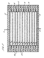
- a redox flow battery 5 is shown in schematic cross-section.
- the battery comprises a stack of twelve bipolar electrodes 6 which are provided at either end of the stack with electrical connections 7 and 8.
- the bipolar electrodes are separated one from another by cation exchange membranes 9 and are each joined to an insulating flow frame 10.
- Each insulating flow frame 10 is joined to the next frame in the stack by a seal between the parts being formed as described with reference to Figures 1A and 1B.
- the upstands on the flow frames 10, which extend continuously or substantially continously around the frames, are shown at 4.
- the upstands 4 are pressed into corresponding continuous or substantially continuous grooves formed in the adjacent flow frame.
- the electrodes 6 are sealed to the insulating flow frames 10 by suitable means, not specifically shown.
- Two electrolytes A and B fill the cavities formed between the alternate sides of the bipolar electrode 6 and the membranes 9.
- the flow distribution means for the electrolytes A and B are not shown.
- the redox flow battery has end plates 11 and 12 which are profiled in such a manner that they can be sealed to the top flow frame shown in the stack and the bottom flow frame shown in the stack, respectively.
- tie bars and end plates may also be required to maintain the integrity of the cell if it is internally pressurized.
- a first component 20 (shown at 10X magnification in Figure 3A) is formed from a deformable thermoplastic material, such as high density polyethylene.
- This component has an opening 21 which has a height corresponding to h.
- the walls of the opening have a minor inward slope beginning at point X on the wall.
- the opening has a width w of 2.614mm and a width w' where the slope of the inner wall terminates of 2.358mm.
- a second component 23 (shown at 10X magnification in Figure 3B) is formed from polyethylene.
- the second component has a upstand 24 formed therein.
- the upstand has a height H which is less than the height h of the opening 21 in Figure 3A.
- the upstand has a width W of 2.512mm which is greater than the width w' of the opening 21.
- the components 20 and 23 are press fitted together with the upstand 24 being pressed into the opening 21 which deforms sufficiently to accommodate it.
- the sealing area between components 20 and 23 is as small as practicable, which facilitates the assembly of the components and also the maintenance of the assembly as the forces generated are smaller than those encountered with designs with a larger sealing area.
Landscapes
- Chemical & Material Sciences (AREA)
- Engineering & Computer Science (AREA)
- Chemical Kinetics & Catalysis (AREA)
- Electrochemistry (AREA)
- Manufacturing & Machinery (AREA)
- General Chemical & Material Sciences (AREA)
- Life Sciences & Earth Sciences (AREA)
- Sustainable Development (AREA)
- Sustainable Energy (AREA)
- Metallurgy (AREA)
- Materials Engineering (AREA)
- Organic Chemistry (AREA)
- Fuel Cell (AREA)
- Battery Electrode And Active Subsutance (AREA)
- Sealing Battery Cases Or Jackets (AREA)
- Micro-Organisms Or Cultivation Processes Thereof (AREA)
- Electrolytic Production Of Non-Metals, Compounds, Apparatuses Therefor (AREA)
- Hybrid Cells (AREA)
- Lining Or Joining Of Plastics Or The Like (AREA)
- Battery Mounting, Suspending (AREA)
- Primary Cells (AREA)
- Secondary Cells (AREA)
Applications Claiming Priority (3)
| Application Number | Priority Date | Filing Date | Title |
|---|---|---|---|
| GB9526577 | 1995-12-28 | ||
| GBGB9526577.3A GB9526577D0 (en) | 1995-12-28 | 1995-12-28 | Method for the fabrication of electrochemical cells |
| PCT/GB1996/003162 WO1997024778A1 (en) | 1995-12-28 | 1996-12-19 | Method for the fabrication of electrochemical cells |
Publications (2)
| Publication Number | Publication Date |
|---|---|
| EP0870342A1 EP0870342A1 (en) | 1998-10-14 |
| EP0870342B1 true EP0870342B1 (en) | 2002-04-03 |
Family
ID=10786111
Family Applications (1)
| Application Number | Title | Priority Date | Filing Date |
|---|---|---|---|
| EP96942514A Expired - Lifetime EP0870342B1 (en) | 1995-12-28 | 1996-12-19 | Method for the fabrication of electrochemical cells |
Country Status (27)
| Country | Link |
|---|---|
| US (1) | US6086643A (cs) |
| EP (1) | EP0870342B1 (cs) |
| JP (1) | JPH11514132A (cs) |
| KR (1) | KR19990076812A (cs) |
| AT (1) | ATE215747T1 (cs) |
| AU (1) | AU709198B2 (cs) |
| BG (1) | BG63282B1 (cs) |
| BR (1) | BR9612369A (cs) |
| CA (1) | CA2239862A1 (cs) |
| CZ (1) | CZ205698A3 (cs) |
| DE (1) | DE69620452T2 (cs) |
| DK (1) | DK0870342T3 (cs) |
| EG (1) | EG21103A (cs) |
| ES (1) | ES2175165T3 (cs) |
| GB (1) | GB9526577D0 (cs) |
| HU (1) | HUP9903761A3 (cs) |
| IL (1) | IL124955A (cs) |
| MY (1) | MY132538A (cs) |
| NO (1) | NO982956L (cs) |
| NZ (1) | NZ324388A (cs) |
| PL (1) | PL327497A1 (cs) |
| PT (1) | PT870342E (cs) |
| SK (1) | SK90198A3 (cs) |
| TW (1) | TW347599B (cs) |
| UA (1) | UA42856C2 (cs) |
| WO (1) | WO1997024778A1 (cs) |
| ZA (1) | ZA9610814B (cs) |
Families Citing this family (91)
| Publication number | Priority date | Publication date | Assignee | Title |
|---|---|---|---|---|
| US6071635A (en) * | 1998-04-03 | 2000-06-06 | Plug Power, L.L.C. | Easily-formable fuel cell assembly fluid flow plate having conductivity and increased non-conductive material |
| US6171374B1 (en) | 1998-05-29 | 2001-01-09 | Ballard Power Systems Inc. | Plate and frame fluid exchanging assembly with unitary plates and seals |
| EP0995818A1 (en) * | 1998-10-12 | 2000-04-26 | Hydrogen Systems N.V. | High pressure electrolyser module |
| US6413665B1 (en) * | 2000-08-31 | 2002-07-02 | Fuelcell Energy, Inc. | Fuel cell stack compression system |
| US6596427B1 (en) | 2000-11-06 | 2003-07-22 | Ballard Power Systems Inc. | Encapsulating seals for electrochemical cell stacks and methods of sealing electrochemical cell stacks |
| JP3571696B2 (ja) | 2001-01-30 | 2004-09-29 | 本田技研工業株式会社 | 燃料電池及び燃料電池スタック |
| US6489054B2 (en) * | 2001-04-19 | 2002-12-03 | Zinc Matrix Power, Inc. | Battery case with edge seal |
| US6852439B2 (en) * | 2001-05-15 | 2005-02-08 | Hydrogenics Corporation | Apparatus for and method of forming seals in fuel cells and fuel cell stacks |
| AU2002344718B2 (en) | 2001-07-13 | 2007-12-13 | Ceramic Fuel Cells Limited | A fuel cell gas separator plate |
| AUPS076502A0 (en) | 2002-02-26 | 2002-03-21 | Ceramic Fuel Cells Limited | A fuel cell gas separator plate |
| AUPR636601A0 (en) * | 2001-07-13 | 2001-08-02 | Ceramic Fuel Cells Limited | Seal for a fuel cell stack |
| US6761991B2 (en) * | 2001-10-16 | 2004-07-13 | Dow Corning Corporation | Seals for fuel cells and fuel cell stacks |
| DE10160905B4 (de) * | 2001-12-12 | 2007-07-19 | Carl Freudenberg Kg | Dichtungsanordnung für Brennstoffzellen, Verfahren zur Herstellung und Verwendung einer solchen Dichtungsanordnung |
| US20040023090A1 (en) * | 2002-03-30 | 2004-02-05 | Pearson Kenneth E. | Fuel cell system |
| DE10216306B4 (de) * | 2002-04-14 | 2008-06-12 | Sgl Carbon Ag | Verfahren zur Herstellung einer Kontaktplatte für eine elektrochemische Zelle sowie deren Verwendungen |
| WO2004051765A2 (en) * | 2002-12-04 | 2004-06-17 | Lynntech Power Systems,Ltd. | Self-aligning components for electrochemical cells |
| WO2004051777A2 (en) * | 2002-12-04 | 2004-06-17 | Lynntech Power Systems, Ltd. | Electrochemical cell plate with integral seals |
| DE10259386A1 (de) * | 2002-12-19 | 2004-07-01 | GHW Gesellschaft für Hochleistungselektrolyseure zur Wasserstofferzeugung mbH | Druckelektrolyseur und Zellrahmen für einen solchen |
| US6916572B2 (en) * | 2003-03-19 | 2005-07-12 | Ird Fuel Cells A/S | Interlocking isolator for fuel cells |
| US20040195716A1 (en) * | 2003-04-01 | 2004-10-07 | Bergmann Blaise F. | Method and system for utilizing low pressure for perforating and consolidating an uncured laminate sheet in one cycle of operation |
| US20050048348A1 (en) * | 2003-08-26 | 2005-03-03 | Hydrogenics Corporation | Fuel cell system and bracket therefor |
| EP1528126A1 (en) | 2003-10-30 | 2005-05-04 | Vandenborre Hydrogen Systems N.V. | An integrated electrolyser module with an internal gas/liquid separator |
| US20050136317A1 (en) * | 2003-12-19 | 2005-06-23 | 3M Innovative Properties Company | Molded multi-part flow field structure |
| US8277964B2 (en) | 2004-01-15 | 2012-10-02 | Jd Holding Inc. | System and method for optimizing efficiency and power output from a vanadium redox battery energy storage system |
| JP4570888B2 (ja) * | 2004-03-18 | 2010-10-27 | 富士重工業株式会社 | 蓄電体装置 |
| KR101065382B1 (ko) * | 2004-06-23 | 2011-09-16 | 삼성에스디아이 주식회사 | 연료 전지 시스템 및 이에 사용되는 스택 |
| US20070212587A1 (en) * | 2005-04-01 | 2007-09-13 | Nick Fragiadakis | Apparatus for and method of forming seals in an electrochemical cell assembly |
| US8273495B2 (en) * | 2005-04-12 | 2012-09-25 | General Electric Company | Electrochemical cell structure and method of making the same |
| US20060228619A1 (en) * | 2005-04-12 | 2006-10-12 | General Electric Company | Electrochemical cell structure |
| US7582378B2 (en) * | 2005-06-30 | 2009-09-01 | Freudenberg-Nok General Partnership | Fuel cell seal and plate features |
| KR100878701B1 (ko) * | 2006-03-13 | 2009-01-14 | 주식회사 엘지화학 | 고율 충방전 원통형 이차전지 |
| US7855005B2 (en) * | 2007-02-12 | 2010-12-21 | Deeya Energy, Inc. | Apparatus and methods of determination of state of charge in a redox flow battery |
| US20110094892A1 (en) * | 2007-05-10 | 2011-04-28 | Zdenek Cerny | Electrolyser |
| DE102007024156B3 (de) * | 2007-05-24 | 2008-12-11 | Siemens Ag | Röntgenabsorptionsgitter |
| NZ564225A (en) * | 2007-12-10 | 2009-10-30 | Printer Ribbon Inkers Pri Ltd | A hydrogen generator utilising a series of spaced apart plates contained within an enclosure |
| US8587150B2 (en) * | 2008-02-28 | 2013-11-19 | Deeya Energy, Inc. | Method and modular system for charging a battery |
| US8865337B2 (en) | 2008-03-24 | 2014-10-21 | Lightening Energy | Modular battery, an interconnector for such batteries and methods related to modular batteries |
| US7927731B2 (en) * | 2008-07-01 | 2011-04-19 | Deeya Energy, Inc. | Redox flow cell |
| US8785023B2 (en) | 2008-07-07 | 2014-07-22 | Enervault Corparation | Cascade redox flow battery systems |
| US7820321B2 (en) | 2008-07-07 | 2010-10-26 | Enervault Corporation | Redox flow battery system for distributed energy storage |
| KR101417107B1 (ko) * | 2008-09-11 | 2014-07-09 | 현대자동차주식회사 | 연료전지 스택용 분리판 |
| CN102246338B (zh) * | 2008-10-10 | 2014-06-11 | 迪亚能源股份有限公司 | 液流电池元电池的热控制 |
| US8236463B2 (en) * | 2008-10-10 | 2012-08-07 | Deeya Energy, Inc. | Magnetic current collector |
| EP2351184A4 (en) * | 2008-10-10 | 2014-07-09 | Deeya Energy Technologies Inc | METHOD AND APPARATUS FOR ESTABLISHING BATTERY CHARGE STATUS |
| US8230736B2 (en) * | 2008-10-10 | 2012-07-31 | Deeya Energy, Inc. | Level sensor for conductive liquids |
| US20100092843A1 (en) * | 2008-10-10 | 2010-04-15 | Deeya Energy Technologies, Inc. | Venturi pumping system in a hydrogen gas circulation of a flow battery |
| WO2010042900A1 (en) * | 2008-10-10 | 2010-04-15 | Deeya Energy Technologies, Inc. | Methods for bonding porous flexible membranes using solvent |
| US8231993B2 (en) * | 2008-10-10 | 2012-07-31 | Deeya Energy, Inc. | Flexible multi-walled tubing assembly |
| US8723489B2 (en) * | 2009-05-28 | 2014-05-13 | Deeya Energy, Inc. | Bi-directional buck-boost circuit |
| CN102460811B (zh) * | 2009-05-28 | 2015-11-25 | 艾默吉电力系统股份有限公司 | 氧化还原流通单元电池再平衡 |
| EP2436080A2 (en) * | 2009-05-28 | 2012-04-04 | Deeya Energy, Inc. | Electrolyte compositions |
| CN102460812B (zh) * | 2009-05-28 | 2014-12-31 | 艾默吉电力系统股份有限公司 | 由原料制备流通电池电解质 |
| US8587255B2 (en) * | 2009-05-28 | 2013-11-19 | Deeya Energy, Inc. | Control system for a flow cell battery |
| US8349477B2 (en) * | 2009-05-28 | 2013-01-08 | Deeya Energy, Inc. | Optical leak detection sensor |
| US20110079074A1 (en) * | 2009-05-28 | 2011-04-07 | Saroj Kumar Sahu | Hydrogen chlorine level detector |
| US8551299B2 (en) * | 2009-05-29 | 2013-10-08 | Deeya Energy, Inc. | Methods of producing hydrochloric acid from hydrogen gas and chlorine gas |
| CN102055000B (zh) | 2009-10-29 | 2015-04-22 | 北京普能世纪科技有限公司 | 氧化还原液流电池和使电池长时间持续运行的方法 |
| WO2011066674A1 (zh) | 2009-12-04 | 2011-06-09 | 北京普能世纪科技有限公司 | 聚合物共混质子交换膜及其制备方法 |
| US8822064B2 (en) * | 2009-12-31 | 2014-09-02 | Lightening Energy | Modular battery with polymeric compression sealing |
| US8951665B2 (en) * | 2010-03-10 | 2015-02-10 | Imergy Power Systems, Inc. | Methods for the preparation of electrolytes for chromium-iron redox flow batteries |
| US10651492B2 (en) | 2010-06-22 | 2020-05-12 | Vrb Energy Inc. | Integrated system for electrochemical energy storage system |
| US9281535B2 (en) | 2010-08-12 | 2016-03-08 | Imergy Power Systems, Inc. | System dongle |
| WO2012048276A2 (en) | 2010-10-08 | 2012-04-12 | Caridianbct, Inc. | Customizable methods and systems of growing and harvesting cells in a hollow fiber bioreactor system |
| KR101226009B1 (ko) * | 2010-10-08 | 2013-01-24 | 삼성중공업 주식회사 | 연료 전지 모듈 및 이를 구비한 연료 전지 선박 |
| JP2013545236A (ja) * | 2010-10-29 | 2013-12-19 | ユーティーシー パワー コーポレイション | 燃料電池アッセンブリシール構成 |
| JP2012104237A (ja) * | 2010-11-05 | 2012-05-31 | Sumitomo Electric Ind Ltd | フレームの接合構造、電池用セルスタック、レドックスフロー電池、および電池用セルスタックの製造方法 |
| US9368770B2 (en) * | 2011-03-23 | 2016-06-14 | GM Global Technology Operations LLC | Battery cooling module foot profile design for a jointless conductive FIN/foot compressed interface connection |
| US8980484B2 (en) | 2011-03-29 | 2015-03-17 | Enervault Corporation | Monitoring electrolyte concentrations in redox flow battery systems |
| US8916281B2 (en) | 2011-03-29 | 2014-12-23 | Enervault Corporation | Rebalancing electrolytes in redox flow battery systems |
| US10141594B2 (en) * | 2011-10-07 | 2018-11-27 | Vrb Energy Inc. | Systems and methods for assembling redox flow battery reactor cells |
| US9853454B2 (en) | 2011-12-20 | 2017-12-26 | Jd Holding Inc. | Vanadium redox battery energy storage system |
| DE102013107516A1 (de) * | 2013-07-16 | 2015-01-22 | Fraunhofer-Gesellschaft zur Förderung der angewandten Forschung e.V. | Zelle und Zellstack einer Redox-Flow-Batterie |
| WO2015073913A1 (en) | 2013-11-16 | 2015-05-21 | Terumo Bct, Inc. | Expanding cells in a bioreactor |
| WO2015148704A1 (en) | 2014-03-25 | 2015-10-01 | Terumo Bct, Inc. | Passive replacement of media |
| EP3198006B1 (en) | 2014-09-26 | 2021-03-24 | Terumo BCT, Inc. | Scheduled feed |
| WO2017004592A1 (en) | 2015-07-02 | 2017-01-05 | Terumo Bct, Inc. | Cell growth with mechanical stimuli |
| US11965175B2 (en) | 2016-05-25 | 2024-04-23 | Terumo Bct, Inc. | Cell expansion |
| US11685883B2 (en) | 2016-06-07 | 2023-06-27 | Terumo Bct, Inc. | Methods and systems for coating a cell growth surface |
| US11104874B2 (en) | 2016-06-07 | 2021-08-31 | Terumo Bct, Inc. | Coating a bioreactor |
| CN117247899A (zh) | 2017-03-31 | 2023-12-19 | 泰尔茂比司特公司 | 细胞扩增 |
| US11624046B2 (en) | 2017-03-31 | 2023-04-11 | Terumo Bct, Inc. | Cell expansion |
| US12234441B2 (en) | 2017-03-31 | 2025-02-25 | Terumo Bct, Inc. | Cell expansion |
| KR20220004698A (ko) * | 2019-05-24 | 2022-01-11 | 어드밴스드 배터리 컨셉츠, 엘엘씨 | 통합된 에지 밀봉부를 갖는 배터리 조립체 및 밀봉부 형성 방법 |
| WO2021122159A1 (de) * | 2019-12-19 | 2021-06-24 | Elringklinger Ag | Elektrochemische vorrichtung und verfahren zum herstellen einer elektrochemischen vorrichtung |
| JP7345112B2 (ja) * | 2020-02-14 | 2023-09-15 | パナソニックIpマネジメント株式会社 | 電解液体生成装置 |
| EP4314244B1 (en) | 2021-03-23 | 2025-07-23 | Terumo BCT, Inc. | Cell capture and expansion |
| CN114039076A (zh) | 2021-11-02 | 2022-02-11 | 北京普能世纪科技有限公司 | 一种全钒液流电池分散式规模化系统 |
| US12209689B2 (en) | 2022-02-28 | 2025-01-28 | Terumo Kabushiki Kaisha | Multiple-tube pinch valve assembly |
| USD1099116S1 (en) | 2022-09-01 | 2025-10-21 | Terumo Bct, Inc. | Display screen or portion thereof with a graphical user interface for displaying cell culture process steps and measurements of an associated bioreactor device |
| DK181620B1 (en) * | 2022-11-18 | 2024-07-25 | Green Hydrogen Systems As | Cell frame for pressurised electrolyser cell stack and electrolyser cell stack comprising a number of such cell frames |
| DE102023124902B4 (de) * | 2023-09-14 | 2025-06-12 | Fraunhofer-Gesellschaft zur Förderung der angewandten Forschung eingetragener Verein | Elektrochemischer reaktor mit umlaufender dichtung |
Family Cites Families (13)
| Publication number | Priority date | Publication date | Assignee | Title |
|---|---|---|---|---|
| US1712897A (en) * | 1924-09-10 | 1929-05-14 | Vesta Battery Corp | Storage battery |
| NL302663A (cs) * | 1962-12-28 | |||
| GB1145751A (en) * | 1965-04-01 | 1969-03-19 | John Thomson Anderson | An electrolyser cell and frame and a method of making the same |
| GB1223127A (en) * | 1967-11-02 | 1971-02-24 | Energy Conversion Ltd | Improvements in and relating to electrochemical cells |
| DE2552471C3 (de) * | 1974-11-25 | 1979-08-23 | Dunlop Australia Ltd., Melbourne, Victoria (Australien) | Elektrische Mehrzellen-Batterie |
| FR2410058A1 (fr) * | 1977-11-29 | 1979-06-22 | Electricite De France | Perfectionnements aux installations de production de gaz par electrolyse d'un liquide |
| US4379814A (en) * | 1981-06-01 | 1983-04-12 | Exxon Research And Engineering Co. | Sheet electrode for electrochemical systems |
| JPS5878372A (ja) * | 1981-11-02 | 1983-05-11 | Hitachi Ltd | 燃料電池 |
| JPS63252368A (ja) * | 1987-04-08 | 1988-10-19 | Toyota Motor Corp | 電解液循環式金属−ハロゲン電池 |
| FR2616663B1 (fr) * | 1987-06-16 | 1989-08-18 | Adir | Nouveaux tripeptides a structure polycyclique azotee, leur procede de preparation et les compositions pharmaceutiques qui les contiennent |
| BR9002822A (pt) * | 1989-06-14 | 1991-08-20 | Dow Chemical Co | Gaxeta para a vedacao de membros planos adjacentes de uma celula eletrolitica e conjunto de celula de eletrolise |
| FR2700639B1 (fr) * | 1993-01-21 | 1995-04-07 | Bertin & Cie | Batterie d'accumulateurs électriques équipée de moyens d'étanchement perfectionnés. |
| DE4342485C1 (de) * | 1993-12-13 | 1995-03-30 | Gore W L & Ass Gmbh | Vorrichtung zur Entfernung von gasförmigen Stoffen aus einem Gasstrom |
-
1995
- 1995-12-28 GB GBGB9526577.3A patent/GB9526577D0/en active Pending
-
1996
- 1996-12-19 PL PL96327497A patent/PL327497A1/xx unknown
- 1996-12-19 WO PCT/GB1996/003162 patent/WO1997024778A1/en not_active Ceased
- 1996-12-19 CA CA002239862A patent/CA2239862A1/en not_active Abandoned
- 1996-12-19 CZ CZ982056A patent/CZ205698A3/cs unknown
- 1996-12-19 JP JP9524097A patent/JPH11514132A/ja active Pending
- 1996-12-19 EP EP96942514A patent/EP0870342B1/en not_active Expired - Lifetime
- 1996-12-19 KR KR1019980704937A patent/KR19990076812A/ko not_active Ceased
- 1996-12-19 HU HU9903761A patent/HUP9903761A3/hu unknown
- 1996-12-19 DE DE69620452T patent/DE69620452T2/de not_active Expired - Fee Related
- 1996-12-19 AT AT96942514T patent/ATE215747T1/de not_active IP Right Cessation
- 1996-12-19 ES ES96942514T patent/ES2175165T3/es not_active Expired - Lifetime
- 1996-12-19 DK DK96942514T patent/DK0870342T3/da active
- 1996-12-19 PT PT96942514T patent/PT870342E/pt unknown
- 1996-12-19 SK SK901-98A patent/SK90198A3/sk unknown
- 1996-12-19 AU AU11648/97A patent/AU709198B2/en not_active Ceased
- 1996-12-19 IL IL12495596A patent/IL124955A/en not_active IP Right Cessation
- 1996-12-19 US US09/091,220 patent/US6086643A/en not_active Expired - Fee Related
- 1996-12-19 UA UA98062901A patent/UA42856C2/uk unknown
- 1996-12-19 BR BR9612369A patent/BR9612369A/pt active Search and Examination
- 1996-12-19 NZ NZ324388A patent/NZ324388A/xx unknown
- 1996-12-20 ZA ZA9610814A patent/ZA9610814B/xx unknown
- 1996-12-23 MY MYPI96005437A patent/MY132538A/en unknown
- 1996-12-25 EG EG118696A patent/EG21103A/xx active
-
1997
- 1997-01-07 TW TW086100112A patent/TW347599B/zh active
-
1998
- 1998-06-24 BG BG102576A patent/BG63282B1/bg unknown
- 1998-06-25 NO NO982956A patent/NO982956L/no not_active Application Discontinuation
Also Published As
| Publication number | Publication date |
|---|---|
| PL327497A1 (en) | 1998-12-21 |
| DE69620452D1 (de) | 2002-05-08 |
| AU1164897A (en) | 1997-07-28 |
| BG63282B1 (bg) | 2001-08-31 |
| WO1997024778A1 (en) | 1997-07-10 |
| CA2239862A1 (en) | 1997-07-10 |
| EG21103A (en) | 2000-11-29 |
| NO982956L (no) | 1998-08-27 |
| HUP9903761A3 (en) | 2003-01-28 |
| HUP9903761A2 (hu) | 2000-03-28 |
| BG102576A (bg) | 1999-04-30 |
| NZ324388A (en) | 1999-03-29 |
| MY132538A (en) | 2007-10-31 |
| DK0870342T3 (da) | 2002-07-29 |
| CZ205698A3 (cs) | 1998-11-11 |
| JPH11514132A (ja) | 1999-11-30 |
| IL124955A (en) | 2001-05-20 |
| ZA9610814B (en) | 1998-06-22 |
| EP0870342A1 (en) | 1998-10-14 |
| SK90198A3 (en) | 1998-11-04 |
| US6086643A (en) | 2000-07-11 |
| TW347599B (en) | 1998-12-11 |
| IL124955A0 (en) | 1999-01-26 |
| GB9526577D0 (en) | 1996-02-28 |
| KR19990076812A (ko) | 1999-10-15 |
| PT870342E (pt) | 2002-09-30 |
| NO982956D0 (no) | 1998-06-25 |
| ES2175165T3 (es) | 2002-11-16 |
| ATE215747T1 (de) | 2002-04-15 |
| DE69620452T2 (de) | 2002-10-31 |
| UA42856C2 (uk) | 2001-11-15 |
| HK1016348A1 (en) | 1999-10-29 |
| AU709198B2 (en) | 1999-08-26 |
| BR9612369A (pt) | 1999-07-13 |
Similar Documents
| Publication | Publication Date | Title |
|---|---|---|
| EP0870342B1 (en) | Method for the fabrication of electrochemical cells | |
| US4721555A (en) | Electrolysis cell seal means | |
| US4915803A (en) | Combination seal and frame cover member for a filter press type electrolytic cell | |
| US9556529B2 (en) | Electrolyser frame concept, method and use | |
| CA2098645A1 (en) | Fuel Cell Stack and Method of Fastening the Same | |
| EP0051380B1 (en) | Sealing means for filter press cells | |
| US4389289A (en) | Bipolar electrolyzer | |
| US4431502A (en) | Sealing means for filter press cells | |
| US4894128A (en) | Membrane unit for electrolytic cell | |
| US4654134A (en) | Combination seal and tentering means for electrolysis cells | |
| CA1242990A (en) | Seal means for electrolytic cells | |
| EP0055931A2 (en) | Gasket lubricating means | |
| KR20050074617A (ko) | 연료 전지용 분리판을 형성하는 방법 및 분리판 | |
| CN119585895A (zh) | 将膜固定至框架的方法、单元堆和使用 | |
| HK1016348B (en) | Method for the fabrication of electrochemical cells | |
| CA1287599C (en) | Membrane unit for electrolytic cell | |
| US5340457A (en) | Electrolytic cell | |
| US4877499A (en) | Membrane unit for electrolytic cell | |
| US20250167403A1 (en) | Method of fixing a membrane to a frame, cell stack and use | |
| JPS63216990A (ja) | 電解槽の密封手段、電解槽アセンブリ、および電解槽密封方法 | |
| CN1206505A (zh) | 制造电化学池的方法 | |
| JPH0661970U (ja) | 電解槽の室枠 | |
| EP0276350A1 (en) | Combination seal and tentering means for electrolysis cells | |
| CA1315734C (en) | Combination seal and tentering means for electrolysis cells | |
| JPS63216989A (ja) | 電解槽の結合密封−幅出し手段およびアセンブリ、電解槽アセンブリ、並びに密封−幅出し方法 |
Legal Events
| Date | Code | Title | Description |
|---|---|---|---|
| PUAI | Public reference made under article 153(3) epc to a published international application that has entered the european phase |
Free format text: ORIGINAL CODE: 0009012 |
|
| 17P | Request for examination filed |
Effective date: 19980608 |
|
| AK | Designated contracting states |
Kind code of ref document: A1 Designated state(s): AT BE CH DE DK ES FI FR GB GR IE IT LI LU MC NL PT SE |
|
| 17Q | First examination report despatched |
Effective date: 19981127 |
|
| GRAG | Despatch of communication of intention to grant |
Free format text: ORIGINAL CODE: EPIDOS AGRA |
|
| GRAG | Despatch of communication of intention to grant |
Free format text: ORIGINAL CODE: EPIDOS AGRA |
|
| GRAG | Despatch of communication of intention to grant |
Free format text: ORIGINAL CODE: EPIDOS AGRA |
|
| GRAH | Despatch of communication of intention to grant a patent |
Free format text: ORIGINAL CODE: EPIDOS IGRA |
|
| GRAH | Despatch of communication of intention to grant a patent |
Free format text: ORIGINAL CODE: EPIDOS IGRA |
|
| RAP1 | Party data changed (applicant data changed or rights of an application transferred) |
Owner name: REGENESYS TECHNOLOGIES LIMITED |
|
| REG | Reference to a national code |
Ref country code: GB Ref legal event code: IF02 |
|
| GRAA | (expected) grant |
Free format text: ORIGINAL CODE: 0009210 |
|
| AK | Designated contracting states |
Kind code of ref document: B1 Designated state(s): AT BE CH DE DK ES FI FR GB GR IE IT LI LU MC NL PT SE |
|
| REF | Corresponds to: |
Ref document number: 215747 Country of ref document: AT Date of ref document: 20020415 Kind code of ref document: T |
|
| REG | Reference to a national code |
Ref country code: CH Ref legal event code: EP |
|
| REF | Corresponds to: |
Ref document number: 69620452 Country of ref document: DE Date of ref document: 20020508 |
|
| REG | Reference to a national code |
Ref country code: IE Ref legal event code: FG4D |
|
| ET | Fr: translation filed | ||
| REG | Reference to a national code |
Ref country code: DK Ref legal event code: T3 |
|
| REG | Reference to a national code |
Ref country code: CH Ref legal event code: NV Representative=s name: E. BLUM & CO. PATENTANWAELTE |
|
| REG | Reference to a national code |
Ref country code: GR Ref legal event code: EP Ref document number: 20020402081 Country of ref document: GR |
|
| REG | Reference to a national code |
Ref country code: PT Ref legal event code: SC4A Free format text: AVAILABILITY OF NATIONAL TRANSLATION Effective date: 20020625 |
|
| REG | Reference to a national code |
Ref country code: ES Ref legal event code: FG2A Ref document number: 2175165 Country of ref document: ES Kind code of ref document: T3 |
|
| PGFP | Annual fee paid to national office [announced via postgrant information from national office to epo] |
Ref country code: GB Payment date: 20021206 Year of fee payment: 7 |
|
| PLBE | No opposition filed within time limit |
Free format text: ORIGINAL CODE: 0009261 |
|
| STAA | Information on the status of an ep patent application or granted ep patent |
Free format text: STATUS: NO OPPOSITION FILED WITHIN TIME LIMIT |
|
| 26N | No opposition filed |
Effective date: 20030106 |
|
| PGFP | Annual fee paid to national office [announced via postgrant information from national office to epo] |
Ref country code: GR Payment date: 20031203 Year of fee payment: 8 |
|
| PGFP | Annual fee paid to national office [announced via postgrant information from national office to epo] |
Ref country code: PT Payment date: 20031204 Year of fee payment: 8 |
|
| PGFP | Annual fee paid to national office [announced via postgrant information from national office to epo] |
Ref country code: DK Payment date: 20031208 Year of fee payment: 8 |
|
| PGFP | Annual fee paid to national office [announced via postgrant information from national office to epo] |
Ref country code: IE Payment date: 20031210 Year of fee payment: 8 |
|
| PGFP | Annual fee paid to national office [announced via postgrant information from national office to epo] |
Ref country code: MC Payment date: 20031211 Year of fee payment: 8 |
|
| PGFP | Annual fee paid to national office [announced via postgrant information from national office to epo] |
Ref country code: LU Payment date: 20031216 Year of fee payment: 8 Ref country code: FI Payment date: 20031216 Year of fee payment: 8 Ref country code: ES Payment date: 20031216 Year of fee payment: 8 Ref country code: CH Payment date: 20031216 Year of fee payment: 8 |
|
| PG25 | Lapsed in a contracting state [announced via postgrant information from national office to epo] |
Ref country code: GB Free format text: LAPSE BECAUSE OF NON-PAYMENT OF DUE FEES Effective date: 20031219 |
|
| PGFP | Annual fee paid to national office [announced via postgrant information from national office to epo] |
Ref country code: FR Payment date: 20031222 Year of fee payment: 8 |
|
| PGFP | Annual fee paid to national office [announced via postgrant information from national office to epo] |
Ref country code: BE Payment date: 20031224 Year of fee payment: 8 |
|
| PGFP | Annual fee paid to national office [announced via postgrant information from national office to epo] |
Ref country code: SE Payment date: 20031230 Year of fee payment: 8 Ref country code: AT Payment date: 20031230 Year of fee payment: 8 |
|
| PGFP | Annual fee paid to national office [announced via postgrant information from national office to epo] |
Ref country code: NL Payment date: 20031231 Year of fee payment: 8 |
|
| PGFP | Annual fee paid to national office [announced via postgrant information from national office to epo] |
Ref country code: DE Payment date: 20040219 Year of fee payment: 8 |
|
| GBPC | Gb: european patent ceased through non-payment of renewal fee |
Effective date: 20031219 |
|
| PG25 | Lapsed in a contracting state [announced via postgrant information from national office to epo] |
Ref country code: FI Free format text: LAPSE BECAUSE OF NON-PAYMENT OF DUE FEES Effective date: 20041204 |
|
| PG25 | Lapsed in a contracting state [announced via postgrant information from national office to epo] |
Ref country code: LU Free format text: LAPSE BECAUSE OF NON-PAYMENT OF DUE FEES Effective date: 20041219 Ref country code: AT Free format text: LAPSE BECAUSE OF NON-PAYMENT OF DUE FEES Effective date: 20041219 |
|
| PG25 | Lapsed in a contracting state [announced via postgrant information from national office to epo] |
Ref country code: SE Free format text: LAPSE BECAUSE OF NON-PAYMENT OF DUE FEES Effective date: 20041220 Ref country code: IE Free format text: LAPSE BECAUSE OF NON-PAYMENT OF DUE FEES Effective date: 20041220 Ref country code: ES Free format text: LAPSE BECAUSE OF NON-PAYMENT OF DUE FEES Effective date: 20041220 |
|
| PG25 | Lapsed in a contracting state [announced via postgrant information from national office to epo] |
Ref country code: MC Free format text: LAPSE BECAUSE OF NON-PAYMENT OF DUE FEES Effective date: 20041231 Ref country code: LI Free format text: LAPSE BECAUSE OF NON-PAYMENT OF DUE FEES Effective date: 20041231 Ref country code: CH Free format text: LAPSE BECAUSE OF NON-PAYMENT OF DUE FEES Effective date: 20041231 Ref country code: BE Free format text: LAPSE BECAUSE OF NON-PAYMENT OF DUE FEES Effective date: 20041231 |
|
| PG25 | Lapsed in a contracting state [announced via postgrant information from national office to epo] |
Ref country code: DK Free format text: LAPSE BECAUSE OF NON-PAYMENT OF DUE FEES Effective date: 20050103 |
|
| PG25 | Lapsed in a contracting state [announced via postgrant information from national office to epo] |
Ref country code: PT Free format text: LAPSE BECAUSE OF NON-PAYMENT OF DUE FEES Effective date: 20050620 |
|
| BERE | Be: lapsed |
Owner name: *REGENESYS TECHNOLOGIES LTD Effective date: 20041231 |
|
| PG25 | Lapsed in a contracting state [announced via postgrant information from national office to epo] |
Ref country code: NL Free format text: LAPSE BECAUSE OF NON-PAYMENT OF DUE FEES Effective date: 20050701 Ref country code: DE Free format text: LAPSE BECAUSE OF NON-PAYMENT OF DUE FEES Effective date: 20050701 |
|
| PG25 | Lapsed in a contracting state [announced via postgrant information from national office to epo] |
Ref country code: GR Free format text: LAPSE BECAUSE OF NON-PAYMENT OF DUE FEES Effective date: 20050704 |
|
| REG | Reference to a national code |
Ref country code: DK Ref legal event code: EBP |
|
| EUG | Se: european patent has lapsed | ||
| REG | Reference to a national code |
Ref country code: CH Ref legal event code: PL |
|
| PG25 | Lapsed in a contracting state [announced via postgrant information from national office to epo] |
Ref country code: FR Free format text: LAPSE BECAUSE OF NON-PAYMENT OF DUE FEES Effective date: 20050831 |
|
| REG | Reference to a national code |
Ref country code: PT Ref legal event code: MM4A Effective date: 20050620 |
|
| NLV4 | Nl: lapsed or anulled due to non-payment of the annual fee |
Effective date: 20050701 |
|
| REG | Reference to a national code |
Ref country code: IE Ref legal event code: MM4A |
|
| REG | Reference to a national code |
Ref country code: FR Ref legal event code: ST |
|
| PG25 | Lapsed in a contracting state [announced via postgrant information from national office to epo] |
Ref country code: IT Free format text: LAPSE BECAUSE OF NON-PAYMENT OF DUE FEES Effective date: 20051219 |
|
| REG | Reference to a national code |
Ref country code: ES Ref legal event code: FD2A Effective date: 20041220 |
|
| BERE | Be: lapsed |
Owner name: *REGENESYS TECHNOLOGIES LTD Effective date: 20041231 |