EP0868866A2 - Drawer slide fitting - Google Patents
Drawer slide fitting Download PDFInfo
- Publication number
- EP0868866A2 EP0868866A2 EP98104666A EP98104666A EP0868866A2 EP 0868866 A2 EP0868866 A2 EP 0868866A2 EP 98104666 A EP98104666 A EP 98104666A EP 98104666 A EP98104666 A EP 98104666A EP 0868866 A2 EP0868866 A2 EP 0868866A2
- Authority
- EP
- European Patent Office
- Prior art keywords
- pull
- rail
- buffers
- drawer
- rails
- Prior art date
- Legal status (The legal status is an assumption and is not a legal conclusion. Google has not performed a legal analysis and makes no representation as to the accuracy of the status listed.)
- Granted
Links
Images


Classifications
-
- A—HUMAN NECESSITIES
- A47—FURNITURE; DOMESTIC ARTICLES OR APPLIANCES; COFFEE MILLS; SPICE MILLS; SUCTION CLEANERS IN GENERAL
- A47B—TABLES; DESKS; OFFICE FURNITURE; CABINETS; DRAWERS; GENERAL DETAILS OF FURNITURE
- A47B88/00—Drawers for tables, cabinets or like furniture; Guides for drawers
- A47B88/40—Sliding drawers; Slides or guides therefor
- A47B88/49—Sliding drawers; Slides or guides therefor with double extensible guides or parts
- A47B88/493—Sliding drawers; Slides or guides therefor with double extensible guides or parts with rollers, ball bearings, wheels, or the like
-
- A—HUMAN NECESSITIES
- A47—FURNITURE; DOMESTIC ARTICLES OR APPLIANCES; COFFEE MILLS; SPICE MILLS; SUCTION CLEANERS IN GENERAL
- A47B—TABLES; DESKS; OFFICE FURNITURE; CABINETS; DRAWERS; GENERAL DETAILS OF FURNITURE
- A47B2210/00—General construction of drawers, guides and guide devices
- A47B2210/0002—Guide construction for drawers
- A47B2210/0029—Guide bearing means
- A47B2210/0032—Balls
- A47B2210/0035—Balls cages therefor, e.g. for telescopic slides
-
- A—HUMAN NECESSITIES
- A47—FURNITURE; DOMESTIC ARTICLES OR APPLIANCES; COFFEE MILLS; SPICE MILLS; SUCTION CLEANERS IN GENERAL
- A47B—TABLES; DESKS; OFFICE FURNITURE; CABINETS; DRAWERS; GENERAL DETAILS OF FURNITURE
- A47B2210/00—General construction of drawers, guides and guide devices
- A47B2210/0002—Guide construction for drawers
- A47B2210/0029—Guide bearing means
- A47B2210/0037—Rollers
- A47B2210/004—Rollers cages therefor, e.g. for telescopic slides
-
- A—HUMAN NECESSITIES
- A47—FURNITURE; DOMESTIC ARTICLES OR APPLIANCES; COFFEE MILLS; SPICE MILLS; SUCTION CLEANERS IN GENERAL
- A47B—TABLES; DESKS; OFFICE FURNITURE; CABINETS; DRAWERS; GENERAL DETAILS OF FURNITURE
- A47B2210/00—General construction of drawers, guides and guide devices
- A47B2210/0002—Guide construction for drawers
- A47B2210/0051—Guide position
- A47B2210/0059—Guide located at the side of the drawer
-
- A—HUMAN NECESSITIES
- A47—FURNITURE; DOMESTIC ARTICLES OR APPLIANCES; COFFEE MILLS; SPICE MILLS; SUCTION CLEANERS IN GENERAL
- A47B—TABLES; DESKS; OFFICE FURNITURE; CABINETS; DRAWERS; GENERAL DETAILS OF FURNITURE
- A47B2210/00—General construction of drawers, guides and guide devices
- A47B2210/0002—Guide construction for drawers
- A47B2210/0064—Guide sequencing or synchronisation
- A47B2210/0081—Telescopic drawer rails with stop blocks, e.g. synchronization buffers
-
- A—HUMAN NECESSITIES
- A47—FURNITURE; DOMESTIC ARTICLES OR APPLIANCES; COFFEE MILLS; SPICE MILLS; SUCTION CLEANERS IN GENERAL
- A47B—TABLES; DESKS; OFFICE FURNITURE; CABINETS; DRAWERS; GENERAL DETAILS OF FURNITURE
- A47B2210/00—General construction of drawers, guides and guide devices
- A47B2210/0091—Drawer movement damping
- A47B2210/0097—Ball or roller cage incorporating damping means
Definitions
- the invention relates to a pull-out guide for drawers with a pull-out rail attached to the drawer, one attached to the cabinet Support rail and preferably one running between these two rails Middle rail on each side of the drawer, with carriages between the rails are arranged, in which load-transmitting rolling elements are mounted, and on the rails Stops are provided which limit the path of the rails, wherein at least one of the carriages is provided on its end faces with buffers, which in the The end positions of the drawer's extension path should rest against the stops of the rails.
- the middle rails run not exactly different from the extension rails. For example, at When opening the drawer, the center rails first stop until they are clear of the Stops of the pull-out rails can be taken.
- the object of the invention is a pull-out guide set mentioned at the beginning to improve their smoothness. A particularly good buffer effect is said be achieved.
- the object of the invention is achieved in that the buffer in one piece with the Carriages molded from plastic and designed as meandering projections.
- At least that with buffers provided carriage has two plate-shaped roller cages, which are at right angles arranged to each other and connected by a web.
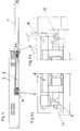
- the pull-out guide assembly according to the invention is equally suitable for assembly to the side of the drawer bottom 3 as well as below the drawer bottom 3, i.e. it can be used with the same advantages as a metal or plastic drawer frame also used in a drawer side wall 2 made of wood, as shown in FIG. 1 will.
- the pull-out guide set according to the invention has support rails on each side of the drawer 5, which is attached to the furniture side wall 1 by means of tabs, and one Middle rail 7 and a pull-out rail 6, which is mounted on the drawer.
- the carriages 8, 11, 12 are arranged in the profiles of the rails 5, 6, 7, in which Store load-bearing rollers and side compensating rollers.
- the carriage 8 is located between the mounting rail 5 and the middle rail 7, while the carriages 11, 12 are arranged between the middle rail 7 and the pull-out rail 6 are.
- the carriages 8, 11 have buffers 9, 10 on their end faces, which as Damping springs are executed.
- the buffers 9, 10 are meandering and describe two opposite U-profiles.
- the buffers 9, 10 with the carriages are advantageous 8, 11 molded in one piece from plastic.
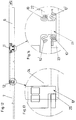
- the carriage 8 is provided with a buffer 9 on each end face.
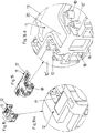
- the carriage 11 has two roller cages 13, 14 directed at right angles to one another, which pass through a horizontal web 20 are connected to each other.
- the buffers 10 are on the front and rear end of the web 20. If the drawer from the Pulled out the furniture body and reaches its front end position, then the pushes front buffers 9 of the carriage 8 on a stop 19 of the mounting rail 5, while on the rear buffer 9 of the carriage 8, a stop 21 of the middle rail 7 presses. 5a and 5b, the situation of the buffer 9 at the beginning of the stroke shown. If the middle rail 7 is moved further out of the furniture body, the Buffer 9, as can be seen from FIGS.
- the carriage 12 as can be seen in particular from FIG. 15, has a U-shaped cross section executed, lateral compensation rollers arranged in both vertical webs are. In this way, good lateral stability of the pull-out guide set is achieved.
Abstract
Description
Die Erfindung bezieht sich auf eine Ausziehführungsgarnitur für Schubladen mit einer an der Schublade befestigten Ausziehschiene, einer am Möbelkorpus befestigten Tragschiene und vorzugsweise einer zwischen diesen beiden Schienen ablaufenden Mittelschiene an jeder Seite der Schublade, wobei zwischen den Schienen Laufwagen angeordnet sind, in denen lastübertragende Walzkörper lagern, und an den Schienen Anschläge vorgesehen sind, die den Laufweg der Schienen begrenzen, wobei mindestens einer der Laufwagen an seinen Stirnseiten mit Puffern versehen ist, die in den Endstellungen des Auszugsweges der Schublade an Anschlägen der Schienen anliegen.The invention relates to a pull-out guide for drawers with a pull-out rail attached to the drawer, one attached to the cabinet Support rail and preferably one running between these two rails Middle rail on each side of the drawer, with carriages between the rails are arranged, in which load-transmitting rolling elements are mounted, and on the rails Stops are provided which limit the path of the rails, wherein at least one of the carriages is provided on its end faces with buffers, which in the The end positions of the drawer's extension path should rest against the stops of the rails.
Bei einer derartigen Ausziehführungsgarnitur mit Mittelschienen laufen die Mittelschienen nicht exakt differential zu den Ausziehschienen ab. Es können beispielsweise beim Öffnen der Schublade die Mittelschienen zuerst stehenbleiben, bis sie von den Anschlägen der Ausziehschienen mitgenommen werden.With such a pull-out guide set with middle rails, the middle rails run not exactly different from the extension rails. For example, at When opening the drawer, the center rails first stop until they are clear of the Stops of the pull-out rails can be taken.
Aufgabe der Erfindung ist es, eine eingangs erwähnte Ausziehführungsgarnitur hinsichtlich ihrer Laufruhe zu verbessern. Dabei soll ein besonders guter Puffereffekt erzielt werden. Insbesondere ist es Aufgabe der Erfindung, die Laufruhe bei einem Vollauszug, bei dem keine besondere Steuerung für die Mittelschienen vorgesehen ist, zu verbessern.The object of the invention is a pull-out guide set mentioned at the beginning to improve their smoothness. A particularly good buffer effect is said be achieved. In particular, it is an object of the invention to ensure smooth running Full extension, in which no special control is provided for the middle rails improve.
Die erfindungsgemäße Aufgabe wird dadurch gelöst, daß die Puffer einstückig mit den Laufwagen aus Kunststoff gespritzt und als mäanderförmige Vorsprünge ausgeführt sind.The object of the invention is achieved in that the buffer in one piece with the Carriages molded from plastic and designed as meandering projections.
Besonders gute Fahreigenschaften werden dadurch erzielt, daß zwischen der Mittelschiene und der Ausziehschiene jeweils zwei Laufwagen angeordnet sind, von denen einer mit Puffern versehen ist.Particularly good driving characteristics are achieved in that between the Middle rail and the pull-out rail are each arranged two carriages one of which is provided with buffers.
Dabei ist vorteilhaft vorgesehen, daß der pufferlose Laufwagen in der vorderen Endstellung der Schublade zwischen je einem Anschlag der Mittelschiene und der Ausziehschiene aufgenommen ist.It is advantageously provided that the bufferless carriage in the front End position of the drawer between each stop of the middle rail and the Pull-out rail is added.
Um eine gute seitliche Führung der Mittelschienen zu erzielen, ist in einem Ausführungsbeispiel der Erfindung vorgesehen, daß zumindestens der mit Puffern versehene Laufwagen zwei plattenförmige Rollenkäfige aufweist, die im rechten Winkel zueinander angeordnet und über einen Steg verbunden sind.To achieve good lateral guidance of the middle rails, is in one Embodiment of the invention provided that at least that with buffers provided carriage has two plate-shaped roller cages, which are at right angles arranged to each other and connected by a web.
Nachfolgend wird ein Ausführungsbeispiel der Erfindung anhand der Figuren der
beiliegenden Zeichnungen eingehend beschrieben.
In den Fig. 2 bis 10 ist jeweils nur eine Seite der Ausziehführungsgarnitur gezeigt; die auf
der gegenüberliegenden Seite der Schublade angeordneten Schienen 5, 6, 7 und
Laufwagen 8, 11, 12 sind analog ausgebildet.2 to 10 only one side of the pull-out guide set is shown; the on
the opposite side of the drawer arranged
Die erfindungsgemäße Ausziehführungsgarnitur eignet sich in gleicher Weise für die Montage
seitlich des Schubladenbodens 3 als auch unterhalb des Schubladenbodens 3, d.h.
sie kann mit den gleichen Vorteilen bei einer Metall- oder Kunststoffschubladenzarge als
auch bei einer Schubladenseitenwand 2 aus Holz, wie sie in der Fig. 1 gezeigt ist, eingesetzt
werden.The pull-out guide assembly according to the invention is equally suitable for assembly
to the side of the
Die erfindungsgemäße Ausziehführungsgarnitur weist an jeder Seite der Schublade Tragschienen
5 auf, die an der Möbelseitenwand 1 mittels Laschen befestigt ist, sowie eine
Mittelschiene 7 und eine Ausziehschiene 6, die an der Schublade montiert ist.The pull-out guide set according to the invention has support rails on each side of the
In den Profilen der Schienen 5, 6, 7 sind die Laufwagen 8, 11, 12 angeordnet, in denen
lastübertragende Laufrollen und seitliche Ausgleichsrollen lagern.The
Die Laufrollen und die seitlichen Ausgleichsrollen sind in den Figuren der Zeichnungen
nicht gezeigt. Im Laufwagen 8 befinden sich die Laufrollen in Rollenkäfigen 15 und die
seitlichen Ausgleichsrollen in Rollenkäfigen 16. In den Laufwagen 11, 12 sind die
Laufrollen in Rollenkäfigen 17 und die seitlichen Ausgleichsrollen in Rollenkäfigen 18
angeordnet.The casters and the side balance rollers are in the figures of the drawings
Not shown. In the
Der Laufwagen 8 befindet sich zwischen der Tragschiene 5 und der Mittelschiene 7, während
die Laufwagen 11, 12 zwischen der Mittelschiene 7 und der Ausziehschiene 6 angeordnet
sind. Die Laufwagen 8, 11 weisen an ihren Stirnseiten Puffer 9, 10 auf, die als
Dämpfungsfedern ausgeführt sind. Die Puffer 9, 10 sind mäanderförmig und beschreiben
zwei einander entgegengerichtete U-Profile. Vorteilhaft sind die Puffer 9, 10 mit den Laufwagen
8, 11 einstückig aus Kunststoff gespritzt.The
Der Laufwagen 8 ist an jeder Stirnseite mit einem Puffer 9 versehen. Der Laufwagen 11
weist zwei im rechten Winkel zueinander gerichtete Rollenkäfige 13, 14 auf, die durch
einen horizontalen Steg 20 miteinander verbunden sind. Die Puffer 10 befinden sich an
der vorderen und hinteren Stirnseite des Steges 20. Wird die Schublade aus dem
Möbelkorpus herausgezogen und erreicht ihre vordere Endstellung, dann stößt der
vordere Puffer 9 des Laufwagens 8 an einem Anschlag 19 der Tragschiene 5 an,
während auf den hinteren Puffer 9 des Laufwagens 8 ein Anschlag 21 der Mittelschiene 7
drückt. In den Fig. 5a und 5b ist die Situation der Puffer 9 am Beginn des Anschlagweges
gezeigt. Wird die Mittelschiene 7 weiter aus dem Möbelkorpus herausbewegt, werden die
Puffer 9, wie aus den Fig. 7a und 7b ersichtlich, zwischen den Anschlägen 19, 21
zusammengedrückt, wobei ein sanfterer und leiserer Anschlag als bei herkömmlichen
Ausziehführungen erzielt wird. Ein Teil der Bewegungsenergie der
Ausziehführungsgarnitur wird von den Puffern 9 absorbiert. Wird keine Kraft auf die
Schublade bzw. auf die Mittelschiene 7 in der Ausziehrichtung ausgeübt, dehnen sich die
Puffer 9 wieder aus.The
In der vorderen Endstellung der Schublade und somit der Ausziehschienen 6 stößt ein
vorderer Puffer 10 an einem Anschlag 22 der Mittelschiene 7 an. während auf einen
hinteren Puffer 10, der dem vorderen Puffer 10 diametral gegenüberliegt, ein Anschlag 23
der Ausziehschiene 6 drückt. Der Laufwagen 12 befindet sich dabei frei zwischen
Anschlägen 24, 25 der Ausziehschiene 6 und der Mittelschiene 7. Wird ein weiterer Zug
auf die Schublade ausgeübt bzw. bedingt durch den Schwung, mit dem die Schublade
aus dem Möbelkorpus herausgezogen wurde, werden die Puffer 10 des Laufwagens 11,
wie in der Fig. 8 gezeigt, zusammengedrückt, wodurch ein Teil der kinematischen Energie
der Schublade absorbiert wird. In der absoluten Endstellung der Schublade wird der
Laufwagen 12 zwischen den Anschlägen 24, 25 der Ausziehschiene 6 und der
Mittelschiene 7 klemmend gehalten. (Fig. 13)In the front end position of the drawer and thus the pull-out
Wird die Schublade in den Möbelkorpus eingeschoben, werden in der hintersten Stellung
der Schublade die Anschläge 9 des Laufwagens 8 wiederum zwischen Anschlägen der
Tragschiene 5 und der Mittelschiene 7 zusammengedrückt. Bei dem zwischen der
Ausziehschiene 6 und der Mittelschiene 7 angeordneten Laufwagen 11 erfolgt die
Stoßabsorbierung jedoch nicht zwischen den Puffern 10, sondern zwischen Puffern 10',
die neben den Puffern 10 angeordnet sind und zueinander ebenso wie die Puffer 10
wiederum diagonal versetzt sind.If the drawer is pushed into the furniture body, it will be in the rearmost position
the drawer the
Der Laufwagen 12 ist, wie insbesondere aus der Fig. 15 ersichtlich, mit U-förmigem Querschnitt
ausgeführt, wobei in beiden Vertikalstegen seitliche Ausgleichsrollen angeordnet
sind. Auf diese Art wird eine gute Seitenstabilität der Ausziehführungsgarnitur erzielt.The
Claims (10)
Priority Applications (1)
| Application Number | Priority Date | Filing Date | Title |
|---|---|---|---|
| AT98104666T ATE253855T1 (en) | 1997-04-01 | 1998-03-16 | EXTENSION SET FOR DRAWERS |
Applications Claiming Priority (3)
| Application Number | Priority Date | Filing Date | Title |
|---|---|---|---|
| AT0054497A AT407002B (en) | 1997-04-01 | 1997-04-01 | EXTENSION GUIDE SET FOR DRAWERS |
| AT54497 | 1997-04-01 | ||
| AT544/97 | 1997-04-01 |
Publications (3)
| Publication Number | Publication Date |
|---|---|
| EP0868866A2 true EP0868866A2 (en) | 1998-10-07 |
| EP0868866A3 EP0868866A3 (en) | 2001-10-04 |
| EP0868866B1 EP0868866B1 (en) | 2003-11-12 |
Family
ID=3493422
Family Applications (1)
| Application Number | Title | Priority Date | Filing Date |
|---|---|---|---|
| EP98104666A Expired - Lifetime EP0868866B1 (en) | 1997-04-01 | 1998-03-16 | Drawer slide fitting |
Country Status (6)
| Country | Link |
|---|---|
| US (1) | US6015199A (en) |
| EP (1) | EP0868866B1 (en) |
| JP (1) | JP3053935U (en) |
| AT (2) | AT407002B (en) |
| DE (1) | DE59810121D1 (en) |
| ES (1) | ES2205299T3 (en) |
Cited By (10)
| Publication number | Priority date | Publication date | Assignee | Title |
|---|---|---|---|---|
| EP1475014A1 (en) * | 2003-05-05 | 2004-11-10 | Julius Blum Gesellschaft m.b.H. | Drawer slide fitting |
| WO2007028593A1 (en) | 2005-09-08 | 2007-03-15 | Paul Hettich Gmbh & Co. Kg | Draw pull guide |
| EP1774870A1 (en) * | 2005-10-11 | 2007-04-18 | Harn Marketing Sdn. Bhd. | Sliding guide rail system for a drawer |
| WO2011150435A1 (en) * | 2010-06-02 | 2011-12-08 | Fulterer Gesellschaft Mbh | Arrangement for drawer pull-out guide |
| ITMI20110834A1 (en) * | 2011-05-12 | 2012-11-13 | Salice Arturo Spa | EXTRACTION GUIDE SET FOR A DRAWER |
| AT512897B1 (en) * | 2012-10-02 | 2013-12-15 | Fulterer Gmbh | Pull-out guide for a piece of furniture which can be pulled out of a furniture carcass |
| AT513608B1 (en) * | 2013-03-12 | 2014-06-15 | Fulterer Gmbh | Pull-out guide for a piece of furniture which can be pulled out of a furniture carcass |
| US8845043B2 (en) | 2010-06-02 | 2014-09-30 | Fulterer Gesellschaft Mbh | Arrangement for a drawer pull-out guide |
| AT520275A1 (en) * | 2017-07-27 | 2019-02-15 | Fulterer Ag & Co Kg | pull-out |
| US10327548B2 (en) | 2016-01-13 | 2019-06-25 | Julius Blum Gmbh | Drawer pull-out guide |
Families Citing this family (26)
| Publication number | Priority date | Publication date | Assignee | Title |
|---|---|---|---|---|
| AT3164U1 (en) * | 1998-11-04 | 1999-11-25 | Fulterer Gmbh | SIDE GUIDE FOR HIGH CABINET EXTENSIONS |
| US20040130248A1 (en) * | 2003-01-03 | 2004-07-08 | Quinn Chi | Flexible bearing spacer |
| ATE526850T1 (en) * | 2003-05-13 | 2011-10-15 | Grass Gmbh | FRONTAL LOCKING DEVICE FOR REleasably engaging a drawer in a drawer slide |
| US20050162053A1 (en) * | 2004-01-26 | 2005-07-28 | Larsen Joseph Jr. | Drawer guide rail assembly with releaseably secured bumpers |
| US20050231083A1 (en) * | 2004-04-15 | 2005-10-20 | Garcie Kent C Jr | Undermount drawer slide |
| US20050229360A1 (en) * | 2004-04-15 | 2005-10-20 | Lowe Mark J | Hinge |
| TWM265495U (en) * | 2004-10-15 | 2005-05-21 | Nan Juen Int Co Ltd | Locking structure with adjustable pulling force for slide rail |
| KR100936228B1 (en) * | 2004-11-05 | 2010-01-11 | 어큐라이드 인터내셔널 인코포레이티드 | Undermount drawer slide |
| US7533946B2 (en) * | 2005-08-25 | 2009-05-19 | Knape & Vogt Manufacturing Company | Closing device for drawers |
| US7815267B1 (en) | 2006-09-15 | 2010-10-19 | Gus Frousiakis | Drawer slide closure apparatus |
| AT505120B1 (en) * | 2007-05-07 | 2012-04-15 | Blum Gmbh Julius | EXTRACTION GUIDE FOR DRAWERS |
| US20080303395A1 (en) * | 2007-06-05 | 2008-12-11 | King Slide Works Co., Ltd. | Buffer bearing for a drawer slide |
| DE202009001962U1 (en) * | 2008-11-03 | 2010-04-01 | Paul Hettich Gmbh & Co. Kg | pull-out guide |
| US8485616B2 (en) * | 2011-02-09 | 2013-07-16 | King Slide Works Co., Ltd. | Slide assembly with buffering member for reducing impact and noise |
| KR101406781B1 (en) * | 2012-10-24 | 2014-06-17 | 박윤식 | Device for attaching and/or detaching slide of drawer |
| DE102014103777A1 (en) * | 2014-03-19 | 2015-09-24 | Schock Metallwerk Gmbh | pull-out guide |
| JP6342687B2 (en) * | 2014-04-01 | 2018-06-13 | 日本アキュライド株式会社 | Slide rail stopper member and slide rail stopper device |
| JP6342688B2 (en) * | 2014-04-01 | 2018-06-13 | 日本アキュライド株式会社 | Slide rail stopper device |
| JP6254890B2 (en) * | 2014-04-01 | 2017-12-27 | 日本アキュライド株式会社 | Slide rail stopper device |
| CN204132846U (en) * | 2014-11-10 | 2015-02-04 | 广东泰明金属制品有限公司 | The synchronous concealed slide track of three joints |
| DE202015006277U1 (en) * | 2015-09-04 | 2017-01-17 | Grass Gmbh | Device for attaching accessories to a furniture component of a piece of furniture |
| DE202015008848U1 (en) * | 2015-12-22 | 2017-03-23 | Grass Gmbh | Guide device for guiding a relative to a furniture body movable furniture part |
| CN105757120A (en) * | 2016-05-18 | 2016-07-13 | 黄国锦 | Stable-running track guide device |
| TWI616166B (en) * | 2017-04-12 | 2018-03-01 | 川湖科技股份有限公司 | Slide rail assembly |
| KR102342578B1 (en) * | 2017-04-28 | 2021-12-23 | 삼성전자주식회사 | Cooking appliance |
| DE102017128752A1 (en) * | 2017-12-04 | 2019-06-06 | Grass Gmbh | Carriage for a guide system, method for producing a carriage |
Family Cites Families (8)
| Publication number | Priority date | Publication date | Assignee | Title |
|---|---|---|---|---|
| CA1125346A (en) * | 1979-11-07 | 1982-06-08 | Jack P. Fler | Three part slide |
| AT375252B (en) * | 1982-08-16 | 1984-07-25 | Fulterer Gmbh | DRAWER EXTRACTOR IN TELESCOPIC DESIGN |
| NL8802030A (en) * | 1988-08-16 | 1990-03-16 | Regout Nv Thomas | TRANSFERABLE THREE-PIECE TELESCOPIC GUIDE. |
| NL9002568A (en) * | 1990-11-26 | 1992-06-16 | Regout Nv Thomas | BALL CAGE FOR TELESCOPIC RAIL, EQUIPPED WITH A CAGE BUFFER. |
| AT401715B (en) * | 1994-01-17 | 1996-11-25 | Blum Gmbh Julius | DIFFERENTIAL EXTRACT FOR DRAWERS |
| AT407473B (en) * | 1994-07-07 | 2001-03-26 | Alfit Ag | FULL EXTENSION FOR DRAWERS |
| DE29507916U1 (en) * | 1995-05-17 | 1995-08-10 | Hettich Paul Gmbh & Co | Drawer drawer slide |
| AT1706U1 (en) * | 1996-11-05 | 1997-10-27 | Blum Gmbh Julius | EXTENSION GUIDE SET FOR DRAWERS |
-
1997
- 1997-04-01 AT AT0054497A patent/AT407002B/en not_active IP Right Cessation
-
1998
- 1998-03-16 AT AT98104666T patent/ATE253855T1/en not_active IP Right Cessation
- 1998-03-16 EP EP98104666A patent/EP0868866B1/en not_active Expired - Lifetime
- 1998-03-16 ES ES98104666T patent/ES2205299T3/en not_active Expired - Lifetime
- 1998-03-16 DE DE59810121T patent/DE59810121D1/en not_active Expired - Lifetime
- 1998-03-20 JP JP1998001666U patent/JP3053935U/en not_active Expired - Lifetime
- 1998-04-01 US US09/053,085 patent/US6015199A/en not_active Expired - Lifetime
Non-Patent Citations (1)
| Title |
|---|
| None |
Cited By (19)
| Publication number | Priority date | Publication date | Assignee | Title |
|---|---|---|---|---|
| EP1475014A1 (en) * | 2003-05-05 | 2004-11-10 | Julius Blum Gesellschaft m.b.H. | Drawer slide fitting |
| WO2007028593A1 (en) | 2005-09-08 | 2007-03-15 | Paul Hettich Gmbh & Co. Kg | Draw pull guide |
| KR101374552B1 (en) * | 2005-09-08 | 2014-03-17 | 파울 헤티히 게엠베하 운트 콤파니 카게 | Draw pull guide |
| EP1774870A1 (en) * | 2005-10-11 | 2007-04-18 | Harn Marketing Sdn. Bhd. | Sliding guide rail system for a drawer |
| US7758135B2 (en) | 2005-10-11 | 2010-07-20 | Harn Marketing Sdn. Bhd. | Sliding guide rail system for a drawer |
| US7762637B2 (en) | 2005-10-11 | 2010-07-27 | Harn Marketing Sdn. Bhd. | Sliding guide rail system for a drawer |
| US8845043B2 (en) | 2010-06-02 | 2014-09-30 | Fulterer Gesellschaft Mbh | Arrangement for a drawer pull-out guide |
| WO2011150435A1 (en) * | 2010-06-02 | 2011-12-08 | Fulterer Gesellschaft Mbh | Arrangement for drawer pull-out guide |
| ITMI20110834A1 (en) * | 2011-05-12 | 2012-11-13 | Salice Arturo Spa | EXTRACTION GUIDE SET FOR A DRAWER |
| WO2012152893A3 (en) * | 2011-05-12 | 2013-01-10 | Arturo Salice S.P.A. | A pull-out guide assembly for a drawer |
| US9039109B2 (en) | 2011-05-12 | 2015-05-26 | Arturo Salice S.P.A. | Pull-out guide assembly for a drawer |
| AT512897B1 (en) * | 2012-10-02 | 2013-12-15 | Fulterer Gmbh | Pull-out guide for a piece of furniture which can be pulled out of a furniture carcass |
| AT512897A4 (en) * | 2012-10-02 | 2013-12-15 | Fulterer Gmbh | Pull-out guide for a piece of furniture which can be pulled out of a furniture carcass |
| AT513608A4 (en) * | 2013-03-12 | 2014-06-15 | Fulterer Gmbh | Pull-out guide for a piece of furniture which can be pulled out of a furniture carcass |
| AT513608B1 (en) * | 2013-03-12 | 2014-06-15 | Fulterer Gmbh | Pull-out guide for a piece of furniture which can be pulled out of a furniture carcass |
| US9301609B2 (en) | 2013-03-12 | 2016-04-05 | Fulterer Gesellschaft Mbh | Pull-out guide for a furniture part which can be pulled out of a basic furniture structure |
| US10327548B2 (en) | 2016-01-13 | 2019-06-25 | Julius Blum Gmbh | Drawer pull-out guide |
| AT520275A1 (en) * | 2017-07-27 | 2019-02-15 | Fulterer Ag & Co Kg | pull-out |
| AT520275B1 (en) * | 2017-07-27 | 2021-08-15 | Fulterer Ag & Co Kg | Pull-out guide |
Also Published As
| Publication number | Publication date |
|---|---|
| EP0868866B1 (en) | 2003-11-12 |
| EP0868866A3 (en) | 2001-10-04 |
| ATA54497A (en) | 2000-04-15 |
| ES2205299T3 (en) | 2004-05-01 |
| DE59810121D1 (en) | 2003-12-18 |
| US6015199A (en) | 2000-01-18 |
| ATE253855T1 (en) | 2003-11-15 |
| AT407002B (en) | 2000-11-27 |
| JP3053935U (en) | 1998-11-17 |
Similar Documents
| Publication | Publication Date | Title |
|---|---|---|
| EP0868866B1 (en) | Drawer slide fitting | |
| AT401717B (en) | LOCKING DEVICE FOR DRAWERS | |
| EP0391221B1 (en) | Closing device for drawers | |
| EP1161163B1 (en) | Guide fittings for pulling-out drawers | |
| EP1066773B1 (en) | Slide | |
| EP0525153B1 (en) | Sliding guide-rail system for drawers | |
| AT401334B (en) | LOCKING DEVICE FOR DRAWERS | |
| EP1475014B1 (en) | Drawer slide fitting | |
| EP1120065A2 (en) | Drawer slide fitting | |
| AT9115U1 (en) | EXTRACTION GUARANTEE FOR DRAWERS OD. DGL. | |
| DE3540787A1 (en) | UNDERFLOOR GUIDE RAIL SET | |
| WO2000059342A1 (en) | Telescopic cupboard drawer | |
| EP0720824B1 (en) | Drawer slide fitting | |
| DE3203839C2 (en) | Pull-out guide set for drawers or the like. | |
| DE3521531C2 (en) | ||
| EP0046531B1 (en) | Telescoping triple slide | |
| DE2613775A1 (en) | Telescopic rail guide system for drawers - ensures simultaneous end positions of centre and inner rails during closing to reduce impact noise | |
| AT399265B (en) | Withdrawal guide (runner) for drawers | |
| DE2607171A1 (en) | Telescopic drawer guide rail - has outer centre and inner rails, roller components in cages and rail guide grooves | |
| AT401716B (en) | Drawer with closing devices | |
| AT4518U1 (en) | EXTENSION GUIDE SET FOR DRAWERS | |
| AT382071B (en) | DRAWER GUIDE | |
| AT406109B (en) | EXTENSION GUIDE SET FOR DRAWERS | |
| AT400797B (en) | Withdrawal guide (runner) for drawers | |
| DE20321394U1 (en) | Drawer rail system comprises two rails attached to carcass, rails attached to drawer bottom and intermediate rails with roller at its front end, two rollers one above the other at its center and one roller at its rear end |
Legal Events
| Date | Code | Title | Description |
|---|---|---|---|
| PUAI | Public reference made under article 153(3) epc to a published international application that has entered the european phase |
Free format text: ORIGINAL CODE: 0009012 |
|
| AK | Designated contracting states |
Kind code of ref document: A2 Designated state(s): AT BE CH DE DK ES FI FR GB GR IE IT LI LU MC NL PT SE Kind code of ref document: A2 Designated state(s): AT DE ES IT |
|
| K1C1 | Correction of patent application (title page) published |
Effective date: 19981007 |
|
| PUAL | Search report despatched |
Free format text: ORIGINAL CODE: 0009013 |
|
| AK | Designated contracting states |
Kind code of ref document: A3 Designated state(s): AT BE CH DE DK ES FI FR GB GR IE IT LI LU MC NL PT SE |
|
| AX | Request for extension of the european patent |
Free format text: AL;LT;LV;MK;RO;SI |
|
| 17P | Request for examination filed |
Effective date: 20020227 |
|
| AKX | Designation fees paid |
Free format text: AT DE ES IT |
|
| GRAH | Despatch of communication of intention to grant a patent |
Free format text: ORIGINAL CODE: EPIDOS IGRA |
|
| GRAS | Grant fee paid |
Free format text: ORIGINAL CODE: EPIDOSNIGR3 |
|
| GRAA | (expected) grant |
Free format text: ORIGINAL CODE: 0009210 |
|
| AK | Designated contracting states |
Kind code of ref document: B1 Designated state(s): AT DE ES IT |
|
| REF | Corresponds to: |
Ref document number: 59810121 Country of ref document: DE Date of ref document: 20031218 Kind code of ref document: P |
|
| PG25 | Lapsed in a contracting state [announced via postgrant information from national office to epo] |
Ref country code: AT Free format text: LAPSE BECAUSE OF NON-PAYMENT OF DUE FEES Effective date: 20040316 |
|
| REG | Reference to a national code |
Ref country code: ES Ref legal event code: FG2A Ref document number: 2205299 Country of ref document: ES Kind code of ref document: T3 |
|
| PLBE | No opposition filed within time limit |
Free format text: ORIGINAL CODE: 0009261 |
|
| STAA | Information on the status of an ep patent application or granted ep patent |
Free format text: STATUS: NO OPPOSITION FILED WITHIN TIME LIMIT |
|
| 26N | No opposition filed |
Effective date: 20040813 |
|
| REG | Reference to a national code |
Ref country code: DE Ref legal event code: R079 Ref document number: 59810121 Country of ref document: DE Free format text: PREVIOUS MAIN CLASS: A47B0088100000 Ipc: A47B0088493000 |
|
| PG25 | Lapsed in a contracting state [announced via postgrant information from national office to epo] |
Ref country code: IT Free format text: LAPSE BECAUSE OF NON-PAYMENT OF DUE FEES Effective date: 20160316 |
|
| PGFP | Annual fee paid to national office [announced via postgrant information from national office to epo] |
Ref country code: DE Payment date: 20170531 Year of fee payment: 20 |
|
| PG25 | Lapsed in a contracting state [announced via postgrant information from national office to epo] |
Ref country code: IT Free format text: LAPSE BECAUSE OF NON-PAYMENT OF DUE FEES Effective date: 20160316 |
|
| PGFP | Annual fee paid to national office [announced via postgrant information from national office to epo] |
Ref country code: ES Payment date: 20170425 Year of fee payment: 20 Ref country code: IT Payment date: 20170323 Year of fee payment: 20 |
|
| PGRI | Patent reinstated in contracting state [announced from national office to epo] |
Ref country code: IT Effective date: 20170710 |
|
| REG | Reference to a national code |
Ref country code: DE Ref legal event code: R071 Ref document number: 59810121 Country of ref document: DE |
|
| REG | Reference to a national code |
Ref country code: ES Ref legal event code: FD2A Effective date: 20220107 |
|
| PG25 | Lapsed in a contracting state [announced via postgrant information from national office to epo] |
Ref country code: ES Free format text: LAPSE BECAUSE OF EXPIRATION OF PROTECTION Effective date: 20180317 |