EP0868370B1 - Beverage container - Google Patents
Beverage container Download PDFInfo
- Publication number
- EP0868370B1 EP0868370B1 EP96943271A EP96943271A EP0868370B1 EP 0868370 B1 EP0868370 B1 EP 0868370B1 EP 96943271 A EP96943271 A EP 96943271A EP 96943271 A EP96943271 A EP 96943271A EP 0868370 B1 EP0868370 B1 EP 0868370B1
- Authority
- EP
- European Patent Office
- Prior art keywords
- compartment
- enclosure
- sidewall
- liquid
- pull tab
- Prior art date
- Legal status (The legal status is an assumption and is not a legal conclusion. Google has not performed a legal analysis and makes no representation as to the accuracy of the status listed.)
- Expired - Lifetime
Links
Images
Classifications
-
- B—PERFORMING OPERATIONS; TRANSPORTING
- B65—CONVEYING; PACKING; STORING; HANDLING THIN OR FILAMENTARY MATERIAL
- B65D—CONTAINERS FOR STORAGE OR TRANSPORT OF ARTICLES OR MATERIALS, e.g. BAGS, BARRELS, BOTTLES, BOXES, CANS, CARTONS, CRATES, DRUMS, JARS, TANKS, HOPPERS, FORWARDING CONTAINERS; ACCESSORIES, CLOSURES, OR FITTINGS THEREFOR; PACKAGING ELEMENTS; PACKAGES
- B65D77/00—Packages formed by enclosing articles or materials in preformed containers, e.g. boxes, cartons, sacks or bags
- B65D77/22—Details
- B65D77/24—Inserts or accessories added or incorporated during filling of containers
-
- B—PERFORMING OPERATIONS; TRANSPORTING
- B65—CONVEYING; PACKING; STORING; HANDLING THIN OR FILAMENTARY MATERIAL
- B65D—CONTAINERS FOR STORAGE OR TRANSPORT OF ARTICLES OR MATERIALS, e.g. BAGS, BARRELS, BOTTLES, BOXES, CANS, CARTONS, CRATES, DRUMS, JARS, TANKS, HOPPERS, FORWARDING CONTAINERS; ACCESSORIES, CLOSURES, OR FITTINGS THEREFOR; PACKAGING ELEMENTS; PACKAGES
- B65D81/00—Containers, packaging elements, or packages, for contents presenting particular transport or storage problems, or adapted to be used for non-packaging purposes after removal of contents
- B65D81/32—Containers, packaging elements, or packages, for contents presenting particular transport or storage problems, or adapted to be used for non-packaging purposes after removal of contents for packaging two or more different materials which must be maintained separate prior to use in admixture
- B65D81/3216—Rigid containers disposed one within the other
-
- B—PERFORMING OPERATIONS; TRANSPORTING
- B65—CONVEYING; PACKING; STORING; HANDLING THIN OR FILAMENTARY MATERIAL
- B65D—CONTAINERS FOR STORAGE OR TRANSPORT OF ARTICLES OR MATERIALS, e.g. BAGS, BARRELS, BOTTLES, BOXES, CANS, CARTONS, CRATES, DRUMS, JARS, TANKS, HOPPERS, FORWARDING CONTAINERS; ACCESSORIES, CLOSURES, OR FITTINGS THEREFOR; PACKAGING ELEMENTS; PACKAGES
- B65D2517/00—Containers specially constructed to be opened by cutting, piercing or tearing of wall portions, e.g. preserving cans or tins
- B65D2517/0001—Details
- B65D2517/001—Action for opening container
- B65D2517/0014—Action for opening container pivot tab and push-down tear panel
-
- B—PERFORMING OPERATIONS; TRANSPORTING
- B65—CONVEYING; PACKING; STORING; HANDLING THIN OR FILAMENTARY MATERIAL
- B65D—CONTAINERS FOR STORAGE OR TRANSPORT OF ARTICLES OR MATERIALS, e.g. BAGS, BARRELS, BOTTLES, BOXES, CANS, CARTONS, CRATES, DRUMS, JARS, TANKS, HOPPERS, FORWARDING CONTAINERS; ACCESSORIES, CLOSURES, OR FITTINGS THEREFOR; PACKAGING ELEMENTS; PACKAGES
- B65D2517/00—Containers specially constructed to be opened by cutting, piercing or tearing of wall portions, e.g. preserving cans or tins
- B65D2517/0001—Details
- B65D2517/0047—Provided with additional elements other than for closing the opening
- B65D2517/0052—Prizes, tokens, badges or other information carrying devices
-
- B—PERFORMING OPERATIONS; TRANSPORTING
- B65—CONVEYING; PACKING; STORING; HANDLING THIN OR FILAMENTARY MATERIAL
- B65D—CONTAINERS FOR STORAGE OR TRANSPORT OF ARTICLES OR MATERIALS, e.g. BAGS, BARRELS, BOTTLES, BOXES, CANS, CARTONS, CRATES, DRUMS, JARS, TANKS, HOPPERS, FORWARDING CONTAINERS; ACCESSORIES, CLOSURES, OR FITTINGS THEREFOR; PACKAGING ELEMENTS; PACKAGES
- B65D2517/00—Containers specially constructed to be opened by cutting, piercing or tearing of wall portions, e.g. preserving cans or tins
- B65D2517/0001—Details
- B65D2517/0058—Other details of container end panel
- B65D2517/0059—General cross-sectional shape of container end panel
- B65D2517/0061—U-shaped
- B65D2517/0062—U-shaped and provided with an additional U-shaped peripheral channel
-
- Y—GENERAL TAGGING OF NEW TECHNOLOGICAL DEVELOPMENTS; GENERAL TAGGING OF CROSS-SECTIONAL TECHNOLOGIES SPANNING OVER SEVERAL SECTIONS OF THE IPC; TECHNICAL SUBJECTS COVERED BY FORMER USPC CROSS-REFERENCE ART COLLECTIONS [XRACs] AND DIGESTS
- Y10—TECHNICAL SUBJECTS COVERED BY FORMER USPC
- Y10S—TECHNICAL SUBJECTS COVERED BY FORMER USPC CROSS-REFERENCE ART COLLECTIONS [XRACs] AND DIGESTS
- Y10S220/00—Receptacles
- Y10S220/906—Beverage can, i.e. beer, soda
Definitions
- This invention relates to containers for holding beverages under pressure and to the manufacture thereof. More particularly, this invention relates primarily to beverage cans used to hold carbonized or carbonated soda drinks and/or fermented beverages under pressure and to the manufacture thereof.
- Carbonized or carbonated soda drink beverages are so commonplace and readily available throughout the world, it can be hard to understand that at one time such products were nonexistent. It is believed that initial efforts to replicate nature's bubbling mineral water began approximately four centuries ago. However, such efforts were without significant success.
- US-A-5 335 813 discloses a double vessel beverage can which comprises two compartments each of which define an enclosure. One of the compartments is disposed within the other. Each compartment is arranged to separately contain a liquid and has an independent opening such that liquid from one compartment can be accessed without opening the other compartment.
- the disclosed can comprises a hollow outer vessel a hollow internal vessel and a cap which seals both vessels. These three distinct components are used to form the two enclosures and a complicated multistep manufacturing process is used to form the can.
- an apparatus for containing a liquid and a product, article, prize, or object comprising:
- a method for manufacturing an apparatus to contain a liquid and a product, article, prize, or object comprising the steps of:
- the second enclosure does not directly communicate with the first enclosure. Consequently, products, articles, prizes, and/or objects stored within the second compartment will not become moistened or soiled by coming in contact with the liquid stored within the first compartment. Similarly, the liquid stored within the first compartment will not become soiled or contaminated by coming into contact with the products, articles, prizes, and/or objects stored within the second compartment.
- the present apparatus contains carbonized or carbonated soda drinks and/or noncarbonated drinks.
- the present apparatus may also be used to contain fermented beverages, such as beer or ale, and other alcoholic and/or nonalcoholic beverages. It is further anticipated that many of these beverages, when thus contained, will be under a pressure exceeding one Atmosphere (1 atm).
- the present apparatus may also be used to contain other liquids without elevated pressurization.
- liquids such as motor oil, petroleum products, hydraulic fluid, brake fluid, paints, lacquers, thinners, stains, oils, varnishes, liquid soaps, stripping compounds, and the like could be contained within the apparatus of the present invention.
- the second compartment could be used to house means for washing or wiping the exterior surfaces of the container and/or the hands and face of the consumer prior to consumption of the beverage.
- the washing or wiping means may comprise one or more moistened towelettes or washcloths. This enables consumers who do not have ready access to washing facilities the ability to clean the container and themselves prior to consuming the beverage.
- the second compartment could be used to house a toy, card, flag, ring, pendant, prize or prize notification, coupon, promotional literature, and/or some other product, article, or object.
- toys depicting characters of currently distributed or soon to be distributed motion pictures can be inserted into the second compartment thus promoting such movies.
- Baseball, basketball, football, hockey, and/or other sports cards, flags, rings, pendants, etc. could be inserted into the second compartment thus promoting individual players, teams, leagues, and/or competitions.
- game cards can be inserted into the second compartment to promote either a game and/or a contest within which the consumer may participate.
- the second compartment may contain a prize or prize notification to the lucky consumer that purchased that particular container.
- the second compartment could also or alternatively contain one or more coupons and/or other promotional literature to entice the consumer to purchase the promoted goods.
- the present apparatus is easily constructed, and inexpensive and economical to manufacture. Once manufactured, the present apparatus would not require an alteration of traditional packaging, shipping, handling or display procedures as currently used within the beverage industry.
- the present apparatus is compact, efficient, reliable, durable, and rugged.
- the second enclosure communicate with an atmosphere exterior to the apparatus without necessarily requiring the opening of the liquid dispensing opening.
- the second compartment is positioned internally within the first compartment and the second compartment communicates with the exterior atmosphere without breaking the seal to the beverage contained within the first compartment, additional space is available for thermal expansion of the liquid beverage inwardly in addition to outwardly. This additional expansion space reduces the likelihood of container breakage if the beverage product was allowed to freeze. Consequently, the design of the present apparatus is believed to be more durable and rugged than the containers that were heretofore available within the beverage industry.
- the liquid beverage contained within the first compartment can be chilled more quickly than would otherwise be possible.
- This enhanced chilling ability is primarily due to the increased surface area to which the liquid beverage is exposed and the fact that the additional surface area contributed by the sidewalls of the second compartment is generally located near the center of the contained liquid beverage.
- This feature of being able to rapidly chill the liquid beverage would be very important to retail store owners because it enables the store to more effectively utilize its refrigeration space. No longer will store owners need to purchase, house, operate, and repair large banks of refrigeration units in order to meet peak demand for chilled beverages. Since the time required to chill the contained beverage is decreased, quickly emptied refrigerator shelf space can be filled with beverage containers at room temperature for quick chilling and still meet the consumer demand for chilled beverages.
- the present apparatus can be used to quickly, efficiency, and easily distribute other products and/or promotional materials through the distribution channels of the beverage industry without incurring additional distribution expenses.
- revenues derived from including the aforementioned promotional materials within the second compartment may significantly defray or compensate some of the otherwise necessary distribution expenses.
- use of the present apparatus may create an additional source of revenue for the beverage manufacturer and distributor.
- the present apparatus also creates an additional avenue for manufacturers and promoters to market their products and/or services, and literally get their advertisements into the hands of potential customers.
- the secondary product, article, prize, or object is generally stored within the second compartment.
- the second compartment is positioned internally within the first compartment. Consequently, the exterior surfaces of the beverage container are still available for printing of trademarks, packaging indicia, and required labeling, without any adverse obstruction by the second compartment or product, article, prize, or object contained therein.
- the present apparatus requires minimal manipulation by the consumer and is extremely simple and easy to use.
- first compartment and the second compartment are positioned internally within first compartment and is integral with the first compartment, both compartments remain intact even after the container is opened and their contents removed. Consequently, the first compartment and the second compartment are disposed of jointly and do not require additional effort on the part of the consumer in order to recycle the container or properly dispose of the container. Furthermore, since the first compartment and the second compartment are preferably manufactured from coated aluminum, both of these elements may be recycled without significant adverse effect upon the environment.
- the present invention also comprises the processes used to manufacture such improved beverage containers.
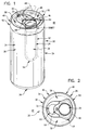
- FIG. 1 is an isometric view of a preferred embodiment of the present invention illustrating the location of the interiorly located second compartment in dotted lines and the movement of the pull tab in phantom lines.
- FIG. 2 is a plan view of the apparatus illustrated in FIG. 1 with the first compartment being joined to the second compartment, and the pull tab being joined to the lid or second compartment.
- the pull tab is illustrated in a position that at least partially obstructs the opening to the second enclosure and prevents the escape of the removable product, article, prize, or object therefrom.
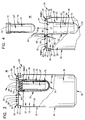
- FIG. 3 is a partially-sectioned, cross-sectional, side-elevational view of the apparatus illustrated in Figures 1 and 2.
- FIG. 4 is a partial, cross-sectional, side-elevational view of the apparatus illustrated in Figures 1, 2, and 3, further illustrating the pull tab having ruptured or broken the seal that defines the liquid dispensing opening to permit access to the first enclosure.
- FIG. 4 also illustrates the placement and removal of an optional container having a lid thereto which contains an expandable, moistened towelette from the second enclosure.
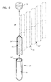
- FIG. 5 is a partially exploded, isometric view of a moistened towelette as illustrated in Figures 3 and 4, further illustrating the enclosure of the towelette within an optional container having a lid thereto and the expandability of the towelette during use.
- the present invention generally comprises an apparatus 20 for containing a liquid 22 and a product, article, prize, or object 24.
- Liquid 22 may take many forms. It is the preference of the inventor that liquid 22 be a carbonized soda drink, a carbonated soda drink, a fermented beverage, and the like. However, liquid 22 may also comprise noncarbonated drinks, motor oil, petroleum products, hydraulic fluid, brake fluid, paints, lacquers, thinners, stains, oils, varnishes, liquid soaps, stripping compounds, and the like.
- Liquid 22 may be contained within apparatus 20 at a pressure exceeding one atmosphere (1 atm) or at a pressure of approximately or about one atmosphere (1 atm).
- product, article, prize, or object 24 comprises a towelette 24'.
- apparatus 20 generally comprises a first compartment 26 and a second compartment 28.
- First compartment 26 defines a first enclosure 30 within which liquid 22 may be contained or dispensed.
- first compartment 26 very closely resembles a conventional soda can, similar to those having a rotatable pop-up tab that can be rotated and pulled upwardly to break a seal on an opening to access the carbonized soda drink contained therein.
- first compartment 26 has an openable liquid dispensing opening 32 which selectively permits access to first enclosure 30.
- first compartment 26 is formed by pressing a thin sheet of aluminum to form a thin walled container 34.
- Container 34 has a generally tubular first sidewall 36 and a first floor 38.
- First floor 38 is formed integrally with first sidewall 36.
- First sidewall 36 has a first upper edge 40 positioned at an opposed end 42 from first floor 38.
- first compartment 26 may take nearly any desirable shape or configuration and still accomplish the purposes of this invention, the inventor prefers that first sidewall 36 be generally cylindrical. However, any tubular shape, albeit having a round, square, triangular, oval, or other cross-sectional appearance, may be similarly be used within the present invention.
- Second compartment 28 defines a second enclosure 44 within which the product, article, prize, or object 24 may be removably contained. When properly joined, second compartment 28 is positioned internally within first compartment 26. In fact, second compartment 28 partially defines the upper reaches or boundaries of first compartment 26.
- second compartment 28 preferably has an opening 46 thereto that is separate from and not in direct communication with liquid dispensing opening 32 of first compartment 26.
- second compartment 28 has opening 46 which selectively permits access to second enclosure 44 without necessarily requiring the opening of liquid dispensing opening 32.
- the product, article, prize, or object 24 contained within second compartment 28 does not directly contact liquid 22 contained within first compartment 26.
- second enclosure 44 preferably does not communicate directly with first enclosure 30.
- second enclosure 44 communicates with an atmosphere 48 exterior to apparatus 20.
- second compartment 28 comprises a pressed aluminum lid 50 having a generally tubular second sidewall 52 and a second floor 54.
- Second floor 54 is preferably formed integrally with second sidewall 52.
- Second sidewall 52 has a second upper edge 56 positioned at an opposed end 57 from second floor 54.
- Second upper edge 56 has a generally planar flange 58 extending radially therefrom.
- Planar flange 58 has an outer perimeter 60.
- lid 50 of apparatus 20 is molded or punched out to form an integral second compartment 28.
- second compartment 28 comprises a separate container that is formed within lid 50 of apparatus 20.
- a portion of second compartment 28 projects or protrudes into a cavity formed within first enclosure 30 of first compartment 26.
- the resulting structure is an inwardly positioned second compartment 28 and a surrounding outwardly positioned first compartment 26 that are separated from one another.
- Second sidewall 52 may take nearly any desirable shape or configuration and still accomplish the purposes of this invention. The inventor, however, prefers that second sidewall 52 be generally cylindrical or conical. By using second sidewall 52 with a slightly conical shape, a plurality of lids 50 may be stacked upon one another for more efficient shipping of component parts of apparatus 20. However, any tubular shape, albeit having a round, square, triangular, oval, or other cross-sectional appearance may similarly be used within the present invention.
- second sidewall 52 may be provided with outwardly radiating thermal flanges, protrusion, or corrugations.
- first compartment 26 and second compartment 28 are manufactured, first compartment 26 is turned upright so that first enclosure 30 may contain liquid 22. Liquid 22 is then poured into first enclosure 30.
- outer perimeter 60 of planar flange 58 is joined to first upper edge 40 of first sidewall 36 to seal in and contain liquid 22. This procedure is usually accomplished by rolling outer perimeter 60 to first upper edge 40. Alternative, or in addition to such rolling, outer perimeter 60 may be welded and/or adhered to first upper edge 40.
- second compartment 28 further defines the boundaries of first compartment 26 and first enclosure 30.
- Planar flange 58 is preferably provided with a breakable seal 62 that is positioned therein. Breakable seal 62 in fact defines liquid dispensing opening 32.
- Apparatus 20 further comprises means 64 for rupturing or breaking seal 62. By rupturing or breaking seal 62, the consumer is permitted selective access to the contents of first enclosure 30.
- rupturing or breaking means 64 comprises a pull tab 66.
- Pull tab 66 is pivotally secured to planar flange 58 by any appropriate means. However, the inventor prefers to pivotally secure pull tab 66 to planar flange 58 by means of a single rivet 68.
- pull tab 66 may appear similar to a conventional pull tab, pull tab 66 of the present invention is much larger and serves an additional purpose from that of a conventional pull tab.
- pull tab 66 is capable of pivoting to at least partially obstruct or not obstruct opening 46 to second enclosure 44.
- pull tab 66 will permit selective access and removal or retention to the contents of second enclosure 44.
- a single pull tab 66 can be used to access the separate openings 32 and 46 both of first compartment 26 and of second compartment 28.
- Opening 46 of second compartment 28 may be provided with a cap, lid, adhesive seal, or the like, to prevent (a) escape of the product, article, prize, or object 24 contained therein, (b) contamination or soiling of the product, article, prize, or object 24 contained therein and/or (c) tampering or theft of the product, article, prize, or object 24 contained therein.
- apparatus 20 may also be provided with a separate receptacle 70, tube, capsule, or the like, to contain the product, article, prize, or object 24.
- receptacle 70 simply houses the product, article, prize, or object 24.
- Receptacle 70 is then inserted, placed, pressed, or snapped into loose or tight engagement with second sidewall 52 of second compartment 28 which define second enclosure 44. If a separate receptacle 70 is used, a cap 72, lid, or seal can be secured to an open end 70' of receptacle 70 to secure the product, article, prize, or object 24 therein.
- the present invention also includes a method for manufacturing apparatus 20 to contain liquid 22 and product, article, prize, or object 24.
- Such method comprises the steps of:
- the aforementioned method may be further restricted by requiring that the additional step of forming means 64 for rupturing or breaking seal 62 thereby permitting selective access to first enclosure 30, rupturing or breaking means 64 being a pull tab 66.
- Another step requires the pivotally securing of pull tab 66 to planar flange 58.
- Another step requires the pivoting of pull tab 66 to at least partially obstruct opening 46 to second enclosure 44 and thereby restrict access second enclosure 44.
- Another step requires the pivoting of pull tab 66 not to obstruct opening to second enclosure 44 and thereby permit access to second enclosure 44.
- Another step requires the pulling of pull tab 66 to rupture or break seal 62 thereby permitting access to first enclosure 30.
- the present invention may be used within most industries wherein a readily dispensable liquid must be contained. Furthermore, the present invention has a special benefit in allowing its use with a wide variety of different liquid products.
- the present invention may be used within the automotive industry to contain motor oil, petroleum, hydraulic fluid, brake fluid, and the like.
- the present invention may be used within the paint and furniture refinishing industries to contain paints, lacquers, thinners, stains, oils, varnishes, and other the like.
- the present invention may be used within the cleaning industry to contain liquid soaps, stripping compounds, and the like.
- the apparatus of this invention is compact, unobtrusive, efficient, durable, rugged, is easily constructed, and is inexpensive and economical to manufacture.
- the preferred embodiment of this invention may utilize preexisting beverage packaging machinery.
- the apparatus of the present invention can be easily transported and displayed without necessarily increasing the packaging size, transportation costs, or the available refrigeration space for display to the consumer.
Landscapes
- Engineering & Computer Science (AREA)
- Mechanical Engineering (AREA)
- Packages (AREA)
- Details Of Rigid Or Semi-Rigid Containers (AREA)
- Distillation Of Fermentation Liquor, Processing Of Alcohols, Vinegar And Beer (AREA)
- Confectionery (AREA)
- Table Devices Or Equipment (AREA)
- Thermally Insulated Containers For Foods (AREA)
Abstract
Description
said first compartment comprises a pressed aluminum container having a generally tubular first sidewall and a first floor formed integrally with said first sidewall, said first sidewall having a first upper edge positioned at an opposed end from said first floor,
characterised in that said second compartment comprises a pressed aluminum lid having a generally tubular second sidewall and a second floor formed integrally with said second sidewall, said second sidewall having a second upper edge positioned at an opposed end from said second floor, said second edge having a generally planar flange extending radially therefrom, said planar flange having an outer perimeter thereof.
Claims (17)
- An apparatus for containing a liquid (22) and a product, article, prize, or object (24) said apparatus comprising:wherein said second enclosure (44) communicates with an atmosphere (48) exterior to said apparatus without necessarily requiring opening of said liquid dispensing opening; and(a) a first compartment (26) defining a first enclosure (30) within which the liquid (22) may be contained or dispensed, said first compartment having an openable liquid dispensing opening (32) which selectively permits access to said first enclosure (30); and(b) a second compartment (28) defining a second enclosure (44) within which the product, article, prize, or object (24) may be removably contained, said second compartment being positioned internally within said first compartment (26), said second enclosure (44) not communicating with said first enclosure (30), said second compartment having an opening (46) which selectively permits access to said second enclosure,
said first compartment comprises a pressed aluminum container (34) having a generally tubular first sidewall (36) and a first floor (38) formed integrally with said first sidewall, said first sidewall (36) having a first upper edge (40) positioned at an opposed end (42) from said first floor (38),
characterised in that said second compartment comprises a pressed aluminum lid (50) having a generally tubular second sidewall (52) and a second floor (54) formed integrally with said second sidewall, said second sidewall (52) having a second upper edge (56) positioned at an opposed end (57) from said second floor (54), said second edge having a generally planar flange (58) extending radially therefrom, said planar flange having an outer perimeter (60) thereof. - Apparatus according to Claim 1, wherein said first sidewall (36) is generally cylindrical.
- Apparatus according to Claim 1, wherein said second sidewall (52) is generally cylindrical or conical.
- Apparatus according to Claim 1, wherein said outer perimeter (60) of said planar flange (58) is joined to said first upper edge (40) of said first sidewall (36), said second compartment (28) further defining said first compartment (26).
- Apparatus according to Claim 4, wherein said planar flange (58) has a breakable seal (62) positioned therein, said breakable seal (62) defining said openable liquid dispensing opening (32).
- Apparatus according to Claim 5, wherein said apparatus further comprises means (64) for rupturing or breaking said seal (62) thereby permitting selective access to said first enclosure (30).
- Apparatus according to Claim 6, wherein said rupturing or breaking means (64) comprises a pull tab (66), said pull tab being pivotally secured to said planar flange (58).
- Apparatus according to Claim 7, wherein said pull tab (66) is capable of pivoting to at least partially obstruct or not obstruct said opening (46) to said second enclosure (44), movement of said pull tab (66) thereby permitting selective access to said second enclosure (44).
- Apparatus according to Claim 8, wherein said liquid (22) contained within said apparatus comprises a carbonized soda drink, a carbonated soda drink, or a fermented beverage.
- Apparatus according to Claim 8, wherein said liquid (22) contained within said apparatus comprises a noncarbonated drink, motor oil, a petroleum product, hydraulic fluid, brake fluid, paint, lacquer, thinner, stain, oil, varnish, liquid soap, or a stripping compound.
- Apparatus according to Claim 9, wherein said liquid (22) is contained within said apparatus at a pressure exceeding one atmosphere.
- A method for manufacturing an apparatus to contain a liquid and a product, article, prize, or object (24) said method comprising the steps of:(a) forming a first compartment (26) which defines a first enclosure (30) within which the liquid (22) may be contained or dispensed, the first compartment (26) having an openable liquid dispensing opening (32) which selectively permits access to the first enclosure (30), the first compartment (26) being manufactured from a pressed aluminum container having a generally tubular first sidewall (36) and a first floor (38) formed integrally with the first sidewall (36), the first sidewall (36) having an first upper edge (40) positioned at an opposed end (42) from the first floor (38), the first sidewall being generally cylindrical;(b) forming a second compartment (28) defining a second enclosure (44) within which the product, article, prize, or object (24) may be removably contained, the second compartment (28) being positioned internally within the first compartment (26), the second enclosure (44) not communicating with the first enclosure (30), the second compartment (28) having an opening (46) which selectively permits access to the second enclosure (44), the second enclosure (44) communicating with an atmosphere (48) exterior to the apparatus (20) without necessarily requiring opening of the liquid dispensing opening (32), the second compartment (28) being manufactured from a pressed aluminum lid (50) having a generally tubular second sidewall (52) and a second floor (54) formed integrally with the second sidewall (52), the second sidewall (52) having a second upper edge (56) positioned at an opposed end (57) from the second floor, the second edge (56) having a generally planar flange (58) extending radially therefrom, the planar flange having an outer perimeter (60) thereof, the second wall being generally cylindrical or conical, the planar flange (58) having a breakable seal (62) positioned therein, the breakable seal defining the openable liquid dispensing opening (32);(c) placing the liquid (22) within the first enclosure (30);(d) joining the outer perimeter (60) of the planar flange (58) to the first upper edge (40) of the first sidewall (36), the second compartment (28) further defining the first compartment (26); and(e) placing the product, article, prize, or object (24) within the second enclosure (44).
- A method according to Claim 12 further comprising the step of forming means (64) for rupturing or breaking the seal (62) thereby permitting selective access to the first enclosure (30), the rupturing or breaking means being a pull tab (66).
- A method according to Claim 13 further comprising the step of pivotally securing the pull tab (66) to the planar flange (58).
- A method according to Claim 14 further comprising the step of pivoting the pull tab (66) to at least partially obstruct the opening (46) to the second enclosure (44) and thereby restrict access the second enclosure (44).
- A method according to Claim 15 further comprising the step of pivoting the pull tab (66) not to obstruct the opening (46) to the second enclosure (44) and thereby permit access to the second enclosure.
- A method according to Claim 16 further comprising the step of pulling the pull tab (66) to rupture or break the seal (62) thereby permitting access to the first enclosure (30).
Applications Claiming Priority (3)
| Application Number | Priority Date | Filing Date | Title |
|---|---|---|---|
| US570894 | 1995-12-12 | ||
| US08/570,894 US5992677A (en) | 1995-12-12 | 1995-12-12 | Dual compartment beverage container |
| PCT/IB1996/001488 WO1997021613A1 (en) | 1995-12-12 | 1996-12-11 | Beverage container |
Publications (2)
| Publication Number | Publication Date |
|---|---|
| EP0868370A1 EP0868370A1 (en) | 1998-10-07 |
| EP0868370B1 true EP0868370B1 (en) | 2000-03-22 |
Family
ID=24281476
Family Applications (1)
| Application Number | Title | Priority Date | Filing Date |
|---|---|---|---|
| EP96943271A Expired - Lifetime EP0868370B1 (en) | 1995-12-12 | 1996-12-11 | Beverage container |
Country Status (7)
| Country | Link |
|---|---|
| US (1) | US5992677A (en) |
| EP (1) | EP0868370B1 (en) |
| JP (1) | JP2000501684A (en) |
| AT (1) | ATE190949T1 (en) |
| AU (1) | AU1205897A (en) |
| DE (1) | DE69607378T2 (en) |
| WO (1) | WO1997021613A1 (en) |
Families Citing this family (42)
| Publication number | Priority date | Publication date | Assignee | Title |
|---|---|---|---|---|
| US6123189A (en) * | 1998-06-15 | 2000-09-26 | The Coca-Cola Company | In-container sachet |
| US6079586A (en) * | 1999-04-15 | 2000-06-27 | Hanneman; Amy L. | Combination cup and food container |
| US20040255787A1 (en) * | 2000-04-25 | 2004-12-23 | Lassota Michael W. | Dispenser with submersible passive heating unit, submersible passive heating unit and method |
| US6808072B2 (en) * | 2000-07-13 | 2004-10-26 | Peter Sedgwick Snedeker | Apparatus for cleansing hands |
| US6382452B1 (en) * | 2000-08-18 | 2002-05-07 | Nebiat T. Getachew | Separable container apparatus |
| US20020144913A1 (en) * | 2001-04-06 | 2002-10-10 | Falkenberg Robert J. | Beverage container with prize delivery receptacle |
| US20030042261A1 (en) * | 2001-08-29 | 2003-03-06 | Cantor David M. | Motorcycle gas tank having a lockable compartment |
| US6971551B2 (en) * | 2002-03-11 | 2005-12-06 | Go Fast Sports And Beverage Company | Beverage transporting and dispensing systems and methods |
| ES1051674Y (en) * | 2002-04-05 | 2003-01-16 | Gonzalez David Gustavo Quispe | PERFECTED DRINK CAN. |
| BR0315208A (en) * | 2002-10-10 | 2005-08-16 | Capstone 411 Pty Ltd | Container Structure |
| US7069739B2 (en) * | 2002-12-18 | 2006-07-04 | Porter Michael A | Device for cooling or heating liquids in a bottle |
| US20040159662A1 (en) * | 2003-02-19 | 2004-08-19 | Johnson Jermaine Marcell | Split can for beverages |
| US6971521B2 (en) * | 2003-02-25 | 2005-12-06 | Pinyot Jeffrey S | Packaging system for multiple discrete foodstuffs |
| CA2424536A1 (en) * | 2003-04-10 | 2004-10-10 | Claude Juneau | Container and method for modifying the composition of a product |
| US20050067414A1 (en) * | 2003-07-28 | 2005-03-31 | Erik Lipson | Multiple cavity container with method and apparatus for forming the same |
| US20050173440A1 (en) * | 2004-02-06 | 2005-08-11 | Kevin Johnson | Multiple-vessel container |
| US20090272747A1 (en) * | 2004-09-15 | 2009-11-05 | Kalaouze Jr Fadi | Multi-compartment fluid storage device |
| US8261929B2 (en) * | 2004-10-07 | 2012-09-11 | Roberts Thomas C | Multiple-opening container and method |
| RU2384494C2 (en) * | 2004-11-26 | 2010-03-20 | Рм Бетайлигунгс Аг | Method for fixation of capsule on plastic bottle neck in process of bottle filling |
| US20060151414A1 (en) * | 2005-01-13 | 2006-07-13 | Mullen Jeffrey D | Bottles, cans, and other storage structures with secondary storage compartments such as cap containers |
| FR2882606A1 (en) * | 2005-02-25 | 2006-09-01 | Jean Francois Poignant | Short announcement making device for use with automatic hot beverage dispenser, has two flaps, where device is provided as cases made up of transparent plastic material and disposed in coffee stirrer loaders for distribution |
| US7954659B2 (en) * | 2005-11-23 | 2011-06-07 | Zuares Daniel J | Drinking cup lid having a plug |
| US20070172303A1 (en) * | 2006-01-26 | 2007-07-26 | Justin Ho | Soap bar with insert |
| WO2007103503A1 (en) * | 2006-03-06 | 2007-09-13 | Roberts Thomas C | Multiple-opening container and method |
| EP2155565A1 (en) | 2007-05-16 | 2010-02-24 | Emergent Technologies, LLC. | Dual constituent container and fabrication process |
| CA2709421A1 (en) * | 2007-12-18 | 2009-06-25 | Sahlstrom Innovation Ab | A top cover for sealing an open end of a cylindrical beverage container, a container, a method for providing a top cover an a method for producing a container |
| US20100000571A1 (en) * | 2008-07-06 | 2010-01-07 | Damon Rosenaur | Bottle Sanitizing Device and Method |
| US20100051576A1 (en) * | 2008-09-04 | 2010-03-04 | Tran Quoc A | Container cap with aqua tissue |
| US9039924B2 (en) | 2010-12-02 | 2015-05-26 | Frosty Cold, Llc | Cooling agent for cold packs and food and beverage containers |
| US10155698B2 (en) | 2010-12-02 | 2018-12-18 | Frosty Cold, Llc | Cooling agent for cold packs and food and beverage containers |
| US9879897B2 (en) | 2010-12-02 | 2018-01-30 | Frosty Cold, Llc | Cooling agent for cold packs and food and beverage containers |
| EP2623431A1 (en) * | 2012-02-06 | 2013-08-07 | Worldwide Packaging Inc. | Product dispensing apparatus with sample holder |
| US8875926B2 (en) * | 2012-03-16 | 2014-11-04 | Valon Grajqevci | Resealable multi-compartment beverage container |
| US9179749B2 (en) | 2012-05-07 | 2015-11-10 | Jordan Creativeworks, Llc | Combination beverage container and storage vessel |
| EP2877068B1 (en) * | 2012-10-05 | 2017-03-01 | Koninklijke Philips N.V. | Multi-functional jug and beverage producing machine using same |
| US11292636B2 (en) | 2013-01-14 | 2022-04-05 | Bottlekeeper, Llc | Protective bottle enclosure |
| US9505527B1 (en) | 2013-01-14 | 2016-11-29 | CamCal Enterprises, LLC | Protective bottle enclosure |
| US9181007B2 (en) | 2013-03-12 | 2015-11-10 | Rexam Beverage Can Company | Beverage can end with vent port |
| US9834362B1 (en) | 2014-10-06 | 2017-12-05 | Mixt Beverages, Inc. | Multi-chambered substance container |
| USD852001S1 (en) | 2018-11-13 | 2019-06-25 | CamCal Enterprises, LLC | Container enclosure |
| USD964094S1 (en) | 2019-08-26 | 2022-09-20 | Bottlekeeper, Llc | Combination container and cap |
| USD955808S1 (en) | 2019-08-26 | 2022-06-28 | Bottlekeeper, Llc | Cap |
Family Cites Families (31)
| Publication number | Priority date | Publication date | Assignee | Title |
|---|---|---|---|---|
| US603316A (en) * | 1898-05-03 | Paper-holding device | ||
| US1255772A (en) * | 1915-12-18 | 1918-02-05 | Roy C Miller | Combination cleaning outfit. |
| US1523297A (en) * | 1921-05-20 | 1925-01-13 | Walter H Savery | Container |
| US1466593A (en) * | 1922-04-15 | 1923-08-28 | Jr Jacob Kirchmer | Washing kit |
| US1577969A (en) * | 1924-11-19 | 1926-03-23 | Shreve & Company | Beverage container |
| US1686200A (en) * | 1926-06-12 | 1928-10-02 | William H Cannard | Toilet kit or container |
| US2096825A (en) * | 1929-07-25 | 1937-10-26 | Roman Benjamin | Preserved multiple course dinner |
| US2080090A (en) * | 1935-12-02 | 1937-05-11 | Clarenee L Mumaugh | Can opener |
| US2197449A (en) * | 1937-02-16 | 1940-04-16 | Fernan O Conill | Liquid container |
| US2331675A (en) * | 1941-09-11 | 1943-10-12 | Frost Gustave | Paper dispenser |
| US2460765A (en) * | 1945-10-29 | 1949-02-01 | Herbert E Palaith | Refrigerating means for containers |
| US3169679A (en) * | 1963-12-06 | 1965-02-16 | Bernard A Hunter | Closure for top perforated cans |
| US3305368A (en) * | 1963-12-09 | 1967-02-21 | Joseph G Bourelle | Beverage package |
| US3217949A (en) * | 1964-04-10 | 1965-11-16 | Dygert & Stone Inc | Dispenser closure and container |
| US3459295A (en) * | 1967-12-04 | 1969-08-05 | Dow Chemical Co | Multiple compartmented container |
| US3732999A (en) * | 1971-05-03 | 1973-05-15 | Ethyl Dev Corp | Bottle with external compartment |
| US3920120A (en) * | 1973-06-11 | 1975-11-18 | Owens Illinois Inc | Combination package |
| US4584848A (en) * | 1983-11-03 | 1986-04-29 | Barnett Eugene R | Container |
| GB8404320D0 (en) * | 1984-02-18 | 1984-03-21 | Metal Box Plc | Closure for container |
| US4651890A (en) * | 1986-05-07 | 1987-03-24 | Coker Gregory F | Beverage can wipe stored in pouch affixed to can |
| US4784678A (en) * | 1987-04-06 | 1988-11-15 | The Coca-Cola Company | Self-cooling container |
| DE3714949C2 (en) * | 1987-05-06 | 1998-11-05 | Hoerauf Michael Maschf | Process for producing a sealed container and a container produced by one of these processes |
| US5056659A (en) * | 1988-09-28 | 1991-10-15 | Howes James P | Prize holding container assemblies |
| US4911320A (en) * | 1988-09-28 | 1990-03-27 | Howes James P | Prize holding container assemblies |
| US5056681A (en) * | 1988-09-28 | 1991-10-15 | Howes James P | Prize holding container assemblies |
| GB8928893D0 (en) * | 1989-12-21 | 1990-02-28 | Whitbread & Co Plc | Carbonated beverage container |
| US5427258A (en) * | 1992-04-09 | 1995-06-27 | Continental Pet Technologies, Inc. | Freestanding container with improved combination of properties |
| US5335813A (en) * | 1992-12-02 | 1994-08-09 | Hao Qi | Double-vessel can |
| US5316398A (en) * | 1993-03-04 | 1994-05-31 | Conros Corporation | Combination bottle and stick |
| US5439103A (en) * | 1994-05-03 | 1995-08-08 | Howes; James P. | Prize holding container assemblies |
| US5492244A (en) * | 1994-07-18 | 1996-02-20 | Kim; Stanley D. C. | Divided aluminum can with independently accessible compartments |
-
1995
- 1995-12-12 US US08/570,894 patent/US5992677A/en not_active Expired - Fee Related
-
1996
- 1996-12-11 AU AU12058/97A patent/AU1205897A/en not_active Abandoned
- 1996-12-11 EP EP96943271A patent/EP0868370B1/en not_active Expired - Lifetime
- 1996-12-11 DE DE69607378T patent/DE69607378T2/en not_active Expired - Fee Related
- 1996-12-11 JP JP9521898A patent/JP2000501684A/en not_active Ceased
- 1996-12-11 AT AT96943271T patent/ATE190949T1/en not_active IP Right Cessation
- 1996-12-11 WO PCT/IB1996/001488 patent/WO1997021613A1/en active IP Right Grant
Also Published As
| Publication number | Publication date |
|---|---|
| US5992677A (en) | 1999-11-30 |
| AU1205897A (en) | 1997-07-03 |
| EP0868370A1 (en) | 1998-10-07 |
| DE69607378D1 (en) | 2000-04-27 |
| JP2000501684A (en) | 2000-02-15 |
| DE69607378T2 (en) | 2000-12-28 |
| ATE190949T1 (en) | 2000-04-15 |
| WO1997021613A1 (en) | 1997-06-19 |
Similar Documents
| Publication | Publication Date | Title |
|---|---|---|
| EP0868370B1 (en) | Beverage container | |
| US7614512B2 (en) | Beverage bottle with storage compartment | |
| EP1804624B1 (en) | Beverage container with removable top | |
| US20110162996A1 (en) | Consumer product with secondary item storage compartment | |
| US8708188B2 (en) | Beverage can marketing device | |
| US6971521B2 (en) | Packaging system for multiple discrete foodstuffs | |
| JPH0676092B2 (en) | Freebie container assembly | |
| NZ555776A (en) | Condiment dispenser for beverage container | |
| CN106536363A (en) | Beverage can marketing device with removable center cover | |
| US20140374370A1 (en) | Beverage bottle with a resealable storage compartment | |
| US20060219592A1 (en) | Article for displaying indicia and holding an object above a container lid | |
| WO2007056815A1 (en) | Beverage drinking vessel and method of dispensing beverages | |
| US20070131700A1 (en) | Reusable beverage container | |
| US20120175274A1 (en) | Beverage bottle with a resealable storage compartment | |
| US4938374A (en) | Beverage containers and method of making same | |
| US20130270144A1 (en) | Beverage bottle with resealable storage compartment | |
| US4112650A (en) | Method of preventing contamination of beverage containers | |
| GB2539025A (en) | Drink receptacle | |
| US20060042969A1 (en) | Packaging system for including digital media disks with consumer products | |
| US20240025593A1 (en) | Multiple fluid storage and selective dispensing bottle | |
| US20030159952A1 (en) | Marketing method and device | |
| KR200375371Y1 (en) | Bottle cap of catching a bottle | |
| JP3054837U (en) | Packaging containers containing canned beer, etc. | |
| RU2188783C2 (en) | Can for drinks | |
| CA2195148C (en) | Carton for a self-pressurised container |
Legal Events
| Date | Code | Title | Description |
|---|---|---|---|
| PUAI | Public reference made under article 153(3) epc to a published international application that has entered the european phase |
Free format text: ORIGINAL CODE: 0009012 |
|
| 17P | Request for examination filed |
Effective date: 19980702 |
|
| AK | Designated contracting states |
Kind code of ref document: A1 Designated state(s): AT BE CH DE DK ES FI FR GB GR IE IT LI LU MC NL PT SE |
|
| 17Q | First examination report despatched |
Effective date: 19981020 |
|
| GRAG | Despatch of communication of intention to grant |
Free format text: ORIGINAL CODE: EPIDOS AGRA |
|
| GRAG | Despatch of communication of intention to grant |
Free format text: ORIGINAL CODE: EPIDOS AGRA |
|
| GRAH | Despatch of communication of intention to grant a patent |
Free format text: ORIGINAL CODE: EPIDOS IGRA |
|
| GRAH | Despatch of communication of intention to grant a patent |
Free format text: ORIGINAL CODE: EPIDOS IGRA |
|
| GRAA | (expected) grant |
Free format text: ORIGINAL CODE: 0009210 |
|
| AK | Designated contracting states |
Kind code of ref document: B1 Designated state(s): AT BE CH DE DK ES FI FR GB GR IE IT LI LU MC NL PT SE |
|
| PG25 | Lapsed in a contracting state [announced via postgrant information from national office to epo] |
Ref country code: SE Free format text: THE PATENT HAS BEEN ANNULLED BY A DECISION OF A NATIONAL AUTHORITY Effective date: 20000322 Ref country code: NL Free format text: LAPSE BECAUSE OF FAILURE TO SUBMIT A TRANSLATION OF THE DESCRIPTION OR TO PAY THE FEE WITHIN THE PRESCRIBED TIME-LIMIT Effective date: 20000322 Ref country code: LI Free format text: LAPSE BECAUSE OF NON-PAYMENT OF DUE FEES Effective date: 20000322 Ref country code: IT Free format text: LAPSE BECAUSE OF FAILURE TO SUBMIT A TRANSLATION OF THE DESCRIPTION OR TO PAY THE FEE WITHIN THE PRE;WARNING: LAPSES OF ITALIAN PATENTS WITH EFFECTIVE DATE BEFORE 2007 MAY HAVE OCCURRED AT ANY TIME BEFORE 2007. THE CORRECT EFFECTIVE DATE MAY BE DIFFERENT FROM THE ONE RECORDED.SCRIBED TIME-LIMIT Effective date: 20000322 Ref country code: GR Free format text: LAPSE BECAUSE OF NON-PAYMENT OF DUE FEES Effective date: 20000322 Ref country code: FR Free format text: THE PATENT HAS BEEN ANNULLED BY A DECISION OF A NATIONAL AUTHORITY Effective date: 20000322 Ref country code: FI Free format text: LAPSE BECAUSE OF FAILURE TO SUBMIT A TRANSLATION OF THE DESCRIPTION OR TO PAY THE FEE WITHIN THE PRESCRIBED TIME-LIMIT Effective date: 20000322 Ref country code: ES Free format text: THE PATENT HAS BEEN ANNULLED BY A DECISION OF A NATIONAL AUTHORITY Effective date: 20000322 Ref country code: CH Free format text: LAPSE BECAUSE OF NON-PAYMENT OF DUE FEES Effective date: 20000322 Ref country code: BE Free format text: LAPSE BECAUSE OF FAILURE TO SUBMIT A TRANSLATION OF THE DESCRIPTION OR TO PAY THE FEE WITHIN THE PRESCRIBED TIME-LIMIT Effective date: 20000322 Ref country code: AT Free format text: LAPSE BECAUSE OF FAILURE TO SUBMIT A TRANSLATION OF THE DESCRIPTION OR TO PAY THE FEE WITHIN THE PRESCRIBED TIME-LIMIT Effective date: 20000322 |
|
| REF | Corresponds to: |
Ref document number: 190949 Country of ref document: AT Date of ref document: 20000415 Kind code of ref document: T |
|
| REG | Reference to a national code |
Ref country code: CH Ref legal event code: EP |
|
| REF | Corresponds to: |
Ref document number: 69607378 Country of ref document: DE Date of ref document: 20000427 |
|
| REG | Reference to a national code |
Ref country code: IE Ref legal event code: FG4D |
|
| ET | Fr: translation filed | ||
| PG25 | Lapsed in a contracting state [announced via postgrant information from national office to epo] |
Ref country code: DK Free format text: LAPSE BECAUSE OF FAILURE TO SUBMIT A TRANSLATION OF THE DESCRIPTION OR TO PAY THE FEE WITHIN THE PRESCRIBED TIME-LIMIT Effective date: 20000622 |
|
| PG25 | Lapsed in a contracting state [announced via postgrant information from national office to epo] |
Ref country code: PT Free format text: LAPSE BECAUSE OF FAILURE TO SUBMIT A TRANSLATION OF THE DESCRIPTION OR TO PAY THE FEE WITHIN THE PRESCRIBED TIME-LIMIT Effective date: 20000623 |
|
| NLV1 | Nl: lapsed or annulled due to failure to fulfill the requirements of art. 29p and 29m of the patents act | ||
| REG | Reference to a national code |
Ref country code: CH Ref legal event code: PL |
|
| PG25 | Lapsed in a contracting state [announced via postgrant information from national office to epo] |
Ref country code: LU Free format text: LAPSE BECAUSE OF NON-PAYMENT OF DUE FEES Effective date: 20001211 Ref country code: IE Free format text: LAPSE BECAUSE OF NON-PAYMENT OF DUE FEES Effective date: 20001211 Ref country code: GB Free format text: LAPSE BECAUSE OF NON-PAYMENT OF DUE FEES Effective date: 20001211 |
|
| PG25 | Lapsed in a contracting state [announced via postgrant information from national office to epo] |
Ref country code: MC Free format text: THE PATENT HAS BEEN ANNULLED BY A DECISION OF A NATIONAL AUTHORITY Effective date: 20001231 |
|
| PLBE | No opposition filed within time limit |
Free format text: ORIGINAL CODE: 0009261 |
|
| STAA | Information on the status of an ep patent application or granted ep patent |
Free format text: STATUS: NO OPPOSITION FILED WITHIN TIME LIMIT |
|
| 26N | No opposition filed | ||
| GBPC | Gb: european patent ceased through non-payment of renewal fee |
Effective date: 20001211 |
|
| PG25 | Lapsed in a contracting state [announced via postgrant information from national office to epo] |
Ref country code: DE Free format text: LAPSE BECAUSE OF NON-PAYMENT OF DUE FEES Effective date: 20011002 |
|
| REG | Reference to a national code |
Ref country code: IE Ref legal event code: MM4A |