EP0867967A2 - Antenne für Telekommunikationsgeräten - Google Patents
Antenne für Telekommunikationsgeräten Download PDFInfo
- Publication number
- EP0867967A2 EP0867967A2 EP98660012A EP98660012A EP0867967A2 EP 0867967 A2 EP0867967 A2 EP 0867967A2 EP 98660012 A EP98660012 A EP 98660012A EP 98660012 A EP98660012 A EP 98660012A EP 0867967 A2 EP0867967 A2 EP 0867967A2
- Authority
- EP
- European Patent Office
- Prior art keywords
- antenna
- plate
- antenna plate
- mobile station
- earth plane
- Prior art date
- Legal status (The legal status is an assumption and is not a legal conclusion. Google has not performed a legal analysis and makes no representation as to the accuracy of the status listed.)
- Granted
Links
- 238000004891 communication Methods 0.000 title claims abstract description 11
- 238000004519 manufacturing process Methods 0.000 claims description 10
- 230000008878 coupling Effects 0.000 claims description 4
- 238000010168 coupling process Methods 0.000 claims description 4
- 238000005859 coupling reaction Methods 0.000 claims description 4
- 239000004020 conductor Substances 0.000 description 28
- PEZNEXFPRSOYPL-UHFFFAOYSA-N (bis(trifluoroacetoxy)iodo)benzene Chemical compound FC(F)(F)C(=O)OI(OC(=O)C(F)(F)F)C1=CC=CC=C1 PEZNEXFPRSOYPL-UHFFFAOYSA-N 0.000 description 12
- 230000005404 monopole Effects 0.000 description 6
- 239000002184 metal Substances 0.000 description 5
- 238000005266 casting Methods 0.000 description 4
- 238000010295 mobile communication Methods 0.000 description 4
- 239000000463 material Substances 0.000 description 3
- 238000000034 method Methods 0.000 description 3
- 239000004033 plastic Substances 0.000 description 3
- 230000001681 protective effect Effects 0.000 description 3
- 238000005553 drilling Methods 0.000 description 2
- 230000000694 effects Effects 0.000 description 2
- 239000011810 insulating material Substances 0.000 description 2
- 238000004080 punching Methods 0.000 description 2
- 239000000853 adhesive Substances 0.000 description 1
- 230000001070 adhesive effect Effects 0.000 description 1
- 230000002411 adverse Effects 0.000 description 1
- 230000003321 amplification Effects 0.000 description 1
- 238000005452 bending Methods 0.000 description 1
- 230000005540 biological transmission Effects 0.000 description 1
- 210000000078 claw Anatomy 0.000 description 1
- 230000006835 compression Effects 0.000 description 1
- 238000007906 compression Methods 0.000 description 1
- 230000007423 decrease Effects 0.000 description 1
- 230000006866 deterioration Effects 0.000 description 1
- 238000010586 diagram Methods 0.000 description 1
- 238000009434 installation Methods 0.000 description 1
- 239000000615 nonconductor Substances 0.000 description 1
- 238000003199 nucleic acid amplification method Methods 0.000 description 1
- 239000002985 plastic film Substances 0.000 description 1
- 239000002994 raw material Substances 0.000 description 1
- 238000005476 soldering Methods 0.000 description 1
- 238000003892 spreading Methods 0.000 description 1
- 239000000126 substance Substances 0.000 description 1
Images


Classifications
-
- H—ELECTRICITY
- H01—ELECTRIC ELEMENTS
- H01Q—ANTENNAS, i.e. RADIO AERIALS
- H01Q1/00—Details of, or arrangements associated with, antennas
- H01Q1/12—Supports; Mounting means
- H01Q1/22—Supports; Mounting means by structural association with other equipment or articles
- H01Q1/24—Supports; Mounting means by structural association with other equipment or articles with receiving set
- H01Q1/241—Supports; Mounting means by structural association with other equipment or articles with receiving set used in mobile communications, e.g. GSM
- H01Q1/242—Supports; Mounting means by structural association with other equipment or articles with receiving set used in mobile communications, e.g. GSM specially adapted for hand-held use
- H01Q1/243—Supports; Mounting means by structural association with other equipment or articles with receiving set used in mobile communications, e.g. GSM specially adapted for hand-held use with built-in antennas
-
- H—ELECTRICITY
- H01—ELECTRIC ELEMENTS
- H01Q—ANTENNAS, i.e. RADIO AERIALS
- H01Q9/00—Electrically-short antennas having dimensions not more than twice the operating wavelength and consisting of conductive active radiating elements
- H01Q9/04—Resonant antennas
- H01Q9/0407—Substantially flat resonant element parallel to ground plane, e.g. patch antenna
- H01Q9/0421—Substantially flat resonant element parallel to ground plane, e.g. patch antenna with a shorting wall or a shorting pin at one end of the element
Definitions
- the present invention relates to an antenna for a wireless communications device according to the preamble of claim 1 and to a mobile station according to the preamble of claim 8.
- Antennas known to be used in mobile stations for the transmission and reception of radio-frequency signals include the monopole antenna and the helix antenna. In order to guarantee correct electrical operation these antennas have to be located in free space outside the case of the mobile station.
- the radio-frequency signals between the radio part of the mobile station and the antenna are usually transmitted by means of conductors and connectors.
- the monopole antenna is in principle a straight conductor above and substantially perpendicular to a conductive plane and its length depends among other things on the frequency range of the radio-frequency signal used.
- GSM mobile communications networks for example, use the 900-MHz frequency range, in which case the corresponding wavelengths in the air are in the range of 30 cm, approximately.
- the length of the antenna wire which typically is about ⁇ /2 for a monopole antenna, should be about 15 cm.
- the length of the antenna conductor can be shortened to some extent by using a so-called lengthening coil in the matching elements of the antenna.
- a known prior-art implementation of the monopole antenna in a mobile station is such that the antenna conductor is placed inside a flexible or rigid and protective tubular piece of insulating material which is further attached to the mobile station by means of a connector.
- This connector also provides an electrical coupling between the antenna and the radio part of the mobile station.
- such an antenna is long in comparison to the mobile station itself and, placed outside the mobile station, susceptible to being damaged, for example by an impact upon dropping.
- monopole antenna is a pull-out structure such that the antenna conductor or the like placed inside the body of a mobile station can be pulled out from the mobile station e.g. for the duration of a call.
- the antenna conductor When pulled out to maximum extension the antenna conductor is locked and at the same electrically coupled to the radio part of the mobile station. After the call the antenna conductor is usually pushed back inside the case of the mobile station.
- the signal amplification is not as good as it would otherwise be, which especially in a weak signal field may cause the connection between the mobile communications system and the mobile station to be cut off. Then the antenna has to be pulled out from the case of the mobile station if the mobile station is to be logged on in the mobile communications system, e.g. to receive incoming calls.
- such a movable antenna comprises parts that become mechanically worn, so in the course of time there may arise a need to replace at least part of the antenna elements.
- careless handling of the mobile station may damage the antenna conductor especially when being pulled out or pushed in.
- the wear and tear of parts and incorrect handling of the antenna may also cause, in addition to the need to replace parts, deterioration of the reliability of the mobile station.
- Helix antenna is a conductor wound into a right-hand or left-hand coil placed above a conductive plane.
- the helix structure provides a shorter antenna than the monopole structure when the operating frequency range is the same.
- a known prior-art implementation of the helix antenna in mobile stations is such that the antenna conductor is placed inside a protective cylindrical or conical piece of insulating material which is further attached to the mobile station by means of a connector. This connector also provides an electrical coupling between the antenna and the radio part of the mobile station. Also this structure, being placed outside the mobile station, is susceptible to damage caused e.g. by dropping the mobile station, as well as to other external impacts.
- an external antenna in a mobile station is susceptible to damage, the antenna itself and the attachment of the antenna to the mobile station have to be made durable and strong, which may impede the attempt to achieve the optimum electrical characteristics for the mobile station and, above all, increase the price of the antenna.
- an external antenna structure means more work stages and, therefore, increases the cost of the assembly work.
- the antenna also has to be suitable for mass production, which means that the connections between the parts of the mobile station and the different parts of the antenna have to be suitable for automatic assembly.
- the external antenna may be situated near the user's head when he is using the phone, which affects the electrical operation of the antenna. Likewise, part of the electrical energy radiated by the antenna may be coupled to the user's head. To reduce that coupled power the external antenna has to be placed in such a manner that it is as far away as possible from the user's head when the mobile station is in the operating position. This also results in some limitations to the design of the mobile station.
- An antenna known to avoid some of the disadvantages of the external antenna is the air-insulated planar inverted F antenna (abbr. PIFA).
- the PIFA antenna comprises a thin parallelogram-shaped antenna plate made of a conductive material such as metal or a plate coated with a conductive material.
- the lengths of the sides of the PIFA antenna depend on the operating frequency range of the antenna. When the operating frequency range is about 880 to 960 MHz, suitable dimensions of the PIFA plate are about 50 mm for the long sides and 25 mm for the short sides. The dimensions of the antenna plate are proportional to the wavelength of the operating frequency range.
- the usable frequency band can also be made wider with a PIFA antenna than with a helix antenna. Then it is also easier to manufacture the PIFA antenna such that the manufacturing tolerances are sufficient to guarantee the desired electrical operation.
- the antenna plate is placed substantially parallel to and at a distance from the structure serving as the earth plane.
- the earth plane may be e.g. an at least partly conductive protective body inside the mobile station.
- One short side of the antenna plate is short-circuited to the earth plane by means of a conductor, and a radio-frequency signal is fed to the antenna plate via an electric circuit having a capacitance and inductance connected in series.
- the capacitance and inductance constitute a series-resonant circuit the resonating frequency of which is dimensioned according to the operating frequency range of the mobile station, which is about 880 to 960 MHz, for example.
- the signal feed point on the antenna plate may be located at the short side of the plate, near the short circuit.
- the capacitance in the series-resonant circuit is located e.g. in the radio part of the mobile station and the inductance is coupled between the antenna plate and the radio part.
- the frequency band of the antenna also depends on the distance between the earth plane and the different elements of the antenna plate, so that if the antenna plate is moved, the frequency band of the antenna is shifted aside from the desired frequency range.
- the antenna plate has to be securely attached to a base.
- the antenna plate In the assembly phase of the mobile station the antenna plate has to be attached precisely at the correct distance from the earth plane. The attachment shall prevent the antenna plate from moving with respect to the earth plane both along the plane of the antenna plate and along the direction perpendicular to that plane.
- An object of this invention is to eliminate aforementioned disadvantages of prior-art antenna structures in mobile stations and to provide an antenna for a mobile station, which antenna is, as regards the manufacture of the different parts of the antenna, as simple as possible and, as regards the assembly of the mobile station, as easily assembled and as reliable as possible.
- the antenna advantageously comprises a PIFA antenna.
- the antenna according to the invention is characterised by what is disclosed in the characterising part of claim 1.
- the mobile station according to the invention is characterised by what is disclosed in the characterising part of claim 8.
- the antenna in question has considerable advantages. Using this antenna, the antenna can be placed inside the outer case of the mobile station so that the antenna is well protected inside the case and faults caused by dropping the mobile station and breaking the external antenna can be avoided. Thanks to the PIFA antenna, the weight of the mobile station can be reduced.
- the PIFA antenna is also simple so that, as regards to the antenna, automatic manufacture and assembly can be applied in the manufacture and production of the mobile station. Furthermore, a fact that adds to the reliability of the mobile station is that there is no need in the PIFA antenna for parts which during operation move with respect to each other, and thus wear out.
- the electrical coupling of the PIFA antenna to an internal printed circuit board can also be realised without big and strong connectors.
- the antenna of the invention makes it possible to reduce the number of work stages in the assembly and at the same time enables accurate positioning of the antenna with respect to the earth plane, which is essential for the operation of the mobile station.
- the structure of the antenna also prevents the antenna plate from being supported by other parts of the antenna, so that external impacts such as bumps, changes of position and movements of the mobile station do not alter the dimensioning of the antenna as far as electrical operation is concerned.
- the antenna according to the invention is reliable and easy to install, thereby being suitable for mass production.
- the small size of the antenna and its adaptability to varying shapes of mobile stations enable easy lay-out design.
- the antenna can be positioned such that during operation it is located at the rear side of the mobile station with respect to the user, which means that compared to an external antenna, considerably less power is coupled to the user's head. At the same time, the adverse effect of the head during operation on the electrical characteristics of the antenna is reduced.
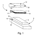
- Fig. 1 shows a preferred embodiment of the antenna 1 according to the invention in connection with a wireless communications device such as a mobile station 2.
- the antenna 1 comprises an antenna plate 3 functioning as a planar radiator.
- the mobile station 2 comprises an earth plane 4 advantageously consisting of an electromagnetic compatibility (EMC) shield of the mobile station the task of which is to prevent interference signals possibly generated by the mobile station 2 from spreading into the environment and, on the other hand, interference signals coming from the environment from affecting the operation of the mobile station 2.
- EMC electromagnetic compatibility
- the radio-frequency signal feed is arranged by means of a feed element 5 coupled between the antenna plate 3 and the radio part 7 (Fig. 3).
- the antenna plate 3 is short-circuited to the earth plane 4 through an earthing element 6 so that electrically the antenna 1 is a quarter-wavelength antenna.
- the feed element 5 is advantageously an inductance and the earthing element 6 is a conductor electrically connected to both the antenna plate 3 and earth plane 4 when the antenna plate is installed in its place.
- Fig. 2a shows in more detail an antenna plate panel 8 for the antenna 1 shown in Fig. 1, and Fig. 2b shows an antenna plate 3 made from the antenna plate panel 8.
- the antenna plate panel 8 is preferably a flexible, thin metal plate or an electrically conductive plate, such as a plate coated with a conductive material.
- the antenna plate 3 functioning as an radiator is planar and advantageously shaped like a parallelogram or polygon. In order to position the antenna plate 3 accurately to a support frame 10 guide holes 9 have been punched or drilled on the antenna plate which are small as compared to the dimensions of the antenna plate 3.
- guide holes 9 have been punched or drilled on the antenna plate which are small as compared to the dimensions of the antenna plate 3.
- the antenna 1 also comprises a feed element 5 made from the same panel and preferably at the same time as the antenna plate 3 by means of punching or other suitable work method, and an earthing element 6.
- the feed element 5 is realised using a stepped metal strip in which the lengths of the steps and the width of the strip at each step depend on the desired electrical operation. Operation of the feed element 5 in connection with the operation of the antenna 1 corresponds to an inductance and the magnitude of the inductance depends on the dimensions and operating frequency range of the feed element 5.
- the structural length of the earthing element 6 and feed element 5 at least equals the distance of their point of attachment in the antenna plate 3 from the corresponding point of attachment in the radio part 7 of the mobile station, depicted in Fig. 1 by a signal conductor interface 15 and earth conductor interface 16 formed in the conductive layer of the printed circuit board 14.
- the distance of the antenna plate 3 from the earth plane 4 can be different at different parts of the antenna plate 3.
- the antenna plate may be curved, for example, as shown in the drawing.
- the curvature corresponds to the shape of the cover structure 12 so that the cover structure 12 supports the antenna plate 3 evenly.
- the nearer the antenna plate 3 and the earth plane 4 are to each other the greater the capacitance between them. This decreases the resonating frequency of the antenna 1 to a certain extent, which has to be taken into account when dimensioning the antenna plate 3 for the desired operating frequency range.
- the antenna plate 3 also comprises spring elements 11 made from the antenna plate panel 8 by means of punching and bending, for example, and attached by one side to said antenna plate.
- the purpose of the spring elements 11 is to brace the antenna plate against the surface of the inner side of the antenna cover structure 12 so as to accurately press the flexible antenna plate 3 to the support frame 10 in order to make sure that the distance of the antenna plate 3 from the earth plane 4 is correct.
- the shape of the antenna plate 3 may be different from the shape of a parallelogram and from planar form so that its positioning in the apparatus has more alternatives.
- the number and positioning of the spring elements 11 depend on the structure of the support frame 10, among other things.
- the earthing element 6 can be replaced by a separate metal earthing conductor and the feed element 5 by a separate metal feed conductor which, wound into a coil, corresponds in its electrical operation to an inductor.
- An radiator can also be produced by using as an antenna plate 3 a moulded or cast plastic sheet coated with an electrically conductive material or formed by mixing an electrically conductive substance in a plastic raw material, for example.
- the antenna 1 according to the invention can also be realised without an earthing element 6, but then the radiator necessarily increases in size.
- An advantageous implementation of the antenna support frame 10 shown in Fig. 2c comprises a planar outer frame 10a made e.g. of plastic by means of casting, and, connected to it, a support structure 10b, 10c.
- the support frame 10 is made of a material which is an electrical insulator.
- the thickness of the support frame 10 may vary in different places.
- the shape of the outermost edge of the continuous outer frame 10a in the support frame 10 advantageously follows the shape of the antenna plate 3 supported by it.
- the support frame 10 comprises guide pins 13 attached to its outer frame 10a or its support structure 10b, 10c such that said pins are substantially perpendicular to the plane of the support frame 10.
- the guide pins 13 are placed on the support frame such that in the assembly of the antenna 1 the guide pins 13 meet the guide holes 9 at the corresponding locations in the antenna plate 3 and fasten it to the support frame 10 along the main plane of the antenna plate 3.
- the support frame's outer frame 10a or its support structure 10b, 10c comprises preferably flexible locking elements 14 located in the support frame preferably at positions corresponding to the outer edges of the antenna plate 3, advantageously in such a manner that the edge of the antenna plate 3 is braced by them.
- the purpose of the locking elements 14 is to lock the support frame 10 to the antenna cover structure 12.
- each locking element 14 a tooth or another clawlike part which in the operating position meets its counterpart (not shown), such as a groove, in the cover structure 12.
- the flexible structure of the locking elements 14 facilitates that the clawlike part is pushed aside and returns when the support frame 10 is installed in the cover structure 12.
- the cover structure 12 preferably comprises flexible counterparts 22 which are pushed against the surface of the antenna plate 3 when the antenna plate 3 is installed.
- the support frame in Fig. 2c also includes for the feed element 5 and earthing element 6 a support base 17 against which the feed element 5 and earthing element 6 formed from the antenna plate panel 8 are placed when the antenna plate 3 is installed.
- Fig. 2d presents a simplified cross section of the antenna 1 according to a first embodiment of the invention in the operating position, ie. installed in a mobile station 2.
- the frequency range is about 880 to 960 MHz, which corresponds to wavelengths of about 34 to 31 cm.
- the size of the antenna plate 3 is about 5 x 2.5 cm and the distance from the earth plane about 2 mm at a first edge and somewhat greater at a second edge.
- the length of the earthing conductor 6 is about 11.5 mm and it is connected to a corner of the antenna plate 3.
- the feed element 5 is connected at about 4 mm from the connection point of the earthing conductor 6, at a distance of about 2 mm from the edge of the antenna plate.
- the earthing conductor 6 can also be realised such that it is coupled directly to the earth plane 4, in which case about 2 mm is a sufficient length for the earthing conductor in the dimensioning example above.
- the contact between the earthing conductor 6 and earth plane 4 can be realised by means of compression, for example.
- a further method of implementation is that a capacitive plate 24, ie. an electrically conductive plate electrically insulated from the earth plane 4, is placed on top of the earth plane 4. Then the capacitive plate 24 and earth plane 4 form a capacitance so that high-frequency signals are short-circuited between the capacitive plate 24 and earth plane 4. This arrangement is illustrated in a simplified manner in the cross section of Fig. 5.
- Fig. 3 shows an example of a feed circuit for the antenna 1 according to the invention, comprising a radio part 7 of a mobile station, said radio part comprising, among other things, a transmitter/receiver TX/RX and an matching capacitance C.
- the matching capacitance C and the inductance used as an antenna feed element 5 constitute a series-resonant circuit preferably tuned to the operating frequency range of the antenna 1, thus increasing the bandwidth of the antenna 1.
- Fig. 4 shows an exploded view of the antenna 1 according to a second preferred embodiment of the invention.
- An advantageously opposite surface of the feed module 18 has contacts 19, 20 which connect the feed element 5 and earthing element 6 to the antenna plate 3 in the operating position.
- This embodiment does not include a support frame 10 proper, but the antenna plate has intermediate supports 21 by means of which the distance of the antenna plate 3 from the earth plane 4 is kept right.
- installation is carried out directly to the mobile station 2, first attaching the feed module 18, then placing the antenna plate 3 at the right spot above the earth plane 4.
- a cover structure 12 which has preferably flexible protrusions 22 by means of which the antenna plate 3 is pressed against the earth plane 4 of the mobile station. Then the antenna plate 3 is held securely in its place in spite of possible impacts and other external forces directed to the mobile station 2.
- the positioning and number of guide pins 13 and locking elements 14 in the support frame may vary according to the application in question.
- the locking elements may also be located in the support frame in such a manner that they penetrate the antenna plate through holes in it.
- the locking and guiding functions can also be combined e.g. by forming in the guide pins 13 a claw or the like which serves as a locking element 14.
- the locking of the support frame 10 to the cover structure 12 can also be arranged using other attaching elements, such as screws or adhesives.
- the antenna cover structure 12 shown in the drawing is advantageously a parallelogram-shaped piece made by casting from a plastic material and having a convex outer surface.
- the concave inner surface of the cover structure 12 has recesses (not shown) made by drilling or in conjunction with the casting.
- the recesses are located in the cover structure 12 at locations corresponding to those of the support frame's guide pins 13 when the antenna is fully assembled.
- the function of the recesses is to align the support frame 10 with respect to the cover structure 12.
- the concave inner surface of the cover structure 12 also includes locking grooves made by drilling or in conjunction with the casting which are located at locations corresponding to those of the support frame's locking elements 14 so that the support frame 10 can be locked to the cover structure 12.
- the shape of the cover structure's 12 edge and the convexity of the outer side may vary greatly according to the components in the immediate vicinity of which the antenna 1 is attached in the mobile station 2.
- the cover structure 12 may comprise one or more holes for the attachment of the antenna 1 to the mobile station 2 by means of screws.
- the cover structure 12 may also have, attached to the collar or edge part, one or more locking elements 14 the purpose of which is to attach to edge locking grooves located at the corresponding locations in the mobile station 2. The attachment of the cover structure 12 secures the correct distance of the antenna plate 3 from the antenna earth plane 4.
- the simple structure of the antenna 1 is a considerable advantage in the assembly work.
- the antenna plate is aligned with the frame structure by means of guide pins 13 and antenna plate guide holes 9, and the antenna plate 3 is formed according to the shape of the support frame 10.
- the support frame 10 with the antenna plate 3 is aligned with the inner surface of the cover structure 12 by means of guide pins 13 and recesses in the cover structure.
- the locking elements 14 in the support frame 10 are locked into edge locking grooves in the cover structure 12.
- Spring elements 11 on the antenna plate 3 are pressed against the inner side of the cover structure 12 and thus push the antenna plate 3 accurately against the support frame 10.
- the compressive effect can be enhanced by placing on the inner surface of the cover structure 12 counterparts 22 made of a flexible material.
- the structure of the antenna 1 according to the invention was above described in conjunction with a mobile station 2, but it is also applicable to other wireless communications devices that use radio-frequency signals in their communications.
- Such devices include radio telephones and cordless telephones, for example.
Landscapes
- Engineering & Computer Science (AREA)
- Computer Networks & Wireless Communication (AREA)
- Support Of Aerials (AREA)
Priority Applications (1)
| Application Number | Priority Date | Filing Date | Title |
|---|---|---|---|
| EP03008548A EP1329982B1 (de) | 1997-03-27 | 1998-02-27 | Antenne für Telekommunikationsgeräte |
Applications Claiming Priority (2)
| Application Number | Priority Date | Filing Date | Title |
|---|---|---|---|
| FI971307 | 1997-03-27 | ||
| FI971307A FI112723B (fi) | 1997-03-27 | 1997-03-27 | Langattomien viestimien antenni |
Related Child Applications (1)
| Application Number | Title | Priority Date | Filing Date |
|---|---|---|---|
| EP03008548A Division EP1329982B1 (de) | 1997-03-27 | 1998-02-27 | Antenne für Telekommunikationsgeräte |
Publications (3)
| Publication Number | Publication Date |
|---|---|
| EP0867967A2 true EP0867967A2 (de) | 1998-09-30 |
| EP0867967A3 EP0867967A3 (de) | 1999-02-03 |
| EP0867967B1 EP0867967B1 (de) | 2003-04-16 |
Family
ID=8548493
Family Applications (2)
| Application Number | Title | Priority Date | Filing Date |
|---|---|---|---|
| EP03008548A Expired - Lifetime EP1329982B1 (de) | 1997-03-27 | 1998-02-27 | Antenne für Telekommunikationsgeräte |
| EP98660012A Expired - Lifetime EP0867967B1 (de) | 1997-03-27 | 1998-02-27 | Antenne für Telekommunikationsgeräte |
Family Applications Before (1)
| Application Number | Title | Priority Date | Filing Date |
|---|---|---|---|
| EP03008548A Expired - Lifetime EP1329982B1 (de) | 1997-03-27 | 1998-02-27 | Antenne für Telekommunikationsgeräte |
Country Status (4)
| Country | Link |
|---|---|
| US (1) | US5914690A (de) |
| EP (2) | EP1329982B1 (de) |
| DE (2) | DE69813357T2 (de) |
| FI (1) | FI112723B (de) |
Cited By (17)
| Publication number | Priority date | Publication date | Assignee | Title |
|---|---|---|---|---|
| EP0924793A2 (de) * | 1997-12-22 | 1999-06-23 | Nortel Networks Corporation | Antennenanordnung für Funktelefon |
| EP0932219A2 (de) * | 1998-01-21 | 1999-07-28 | Lk-Products Oy | Planare Antenne |
| EP1094544A2 (de) * | 1999-10-22 | 2001-04-25 | Lucent Technologies Inc. | Patchantenne mit nichtleitendem Rahmen |
| EP1094543A2 (de) * | 1999-10-22 | 2001-04-25 | Lucent Technologies Inc. | Patchantenne mit nichtleitendem, thermisch geformtem Rahmen |
| WO2001037369A1 (en) * | 1999-11-19 | 2001-05-25 | Allgon Ab | An antenna device and a communication device comprising such an antenna device |
| EP1122815A2 (de) * | 2000-02-02 | 2001-08-08 | Nokia Mobile Phones Ltd. | Antenne für ein Funktelefon |
| EP1137099A2 (de) * | 2000-03-16 | 2001-09-26 | Nokia Mobile Phones Ltd. | Antennenverbinder |
| EP1187255A2 (de) * | 2000-08-31 | 2002-03-13 | Nokia Corporation | Antennenanordnung für ein Kommunikationsendgerät |
| EP1198862A1 (de) * | 1999-05-31 | 2002-04-24 | Allgon AB | Antennenanoednung und teil einer telekommunikationsausrüstung mit einer derartigen anordnung |
| EP1209760A2 (de) * | 2000-11-22 | 2002-05-29 | Matsushita Electric Industrial Co., Ltd. | Eingebaute Antenne für ein mobiles Funkgerät |
| US6437745B1 (en) | 1999-10-20 | 2002-08-20 | Nokia Corporation | Expansion card for wireless data transmission and antenna structure for the same |
| WO2002073737A1 (en) * | 2001-03-13 | 2002-09-19 | Gigaant Ab | Antenna device |
| WO2002082582A1 (en) * | 2001-04-09 | 2002-10-17 | Molex Incorporated | Antenna structures |
| WO2003010853A1 (en) * | 2001-07-21 | 2003-02-06 | Koninklijke Philips Electronics N.V. | Antenna arrangement |
| WO2005006493A1 (en) * | 2003-07-10 | 2005-01-20 | Koninklijke Philips Electronics N.V. | Communication device and an antenna therefor |
| EP1748514A1 (de) * | 2004-06-11 | 2007-01-31 | Matsushita Electric Industrial Co., Ltd. | Mobiler radioterminal |
| EP1777782A1 (de) * | 2005-10-20 | 2007-04-25 | Ace Antenna Corp. | Breitbandantenne mit Impedanztransformation |
Families Citing this family (17)
| Publication number | Priority date | Publication date | Assignee | Title |
|---|---|---|---|---|
| US6326921B1 (en) * | 2000-03-14 | 2001-12-04 | Telefonaktiebolaget Lm Ericsson (Publ) | Low profile built-in multi-band antenna |
| US7452656B2 (en) | 2001-03-26 | 2008-11-18 | Ertek Inc. | Electrically conductive patterns, antennas and methods of manufacture |
| US6582887B2 (en) * | 2001-03-26 | 2003-06-24 | Daniel Luch | Electrically conductive patterns, antennas and methods of manufacture |
| US7564409B2 (en) * | 2001-03-26 | 2009-07-21 | Ertek Inc. | Antennas and electrical connections of electrical devices |
| US7394425B2 (en) * | 2001-03-26 | 2008-07-01 | Daniel Luch | Electrically conductive patterns, antennas and methods of manufacture |
| EP1764860A1 (de) * | 2001-04-11 | 2007-03-21 | LG Electronics Inc. | Intern am Display angeordnete Antenne für mobile elektronische Geräte und zugehöriges mobiles elektronisches Gerät |
| US7072690B2 (en) * | 2001-04-11 | 2006-07-04 | Lg Electronics Inc. | Multi-band antenna and notebook computer with built-in multi-band antenna |
| JP3665620B2 (ja) * | 2002-03-28 | 2005-06-29 | 株式会社東芝 | 無線データ通信用カード及びそれに適用するアンテナ |
| RU2233017C1 (ru) * | 2002-12-02 | 2004-07-20 | Общество с ограниченной ответственностью "Алгоритм" | Антенное устройство с управляемой диаграммой направленности и планарная направленная антенна |
| TWI281782B (en) * | 2002-12-25 | 2007-05-21 | Quanta Comp Inc | Portable wireless device |
| TWI248700B (en) * | 2003-07-04 | 2006-02-01 | Hon Hai Prec Ind Co Ltd | Film antenna and method for manufacturing the same |
| US7180448B2 (en) * | 2003-09-22 | 2007-02-20 | Centurion Wireless Technologies, Inc. | Planar inverted F antenna and method of making the same |
| US7274340B2 (en) * | 2005-12-28 | 2007-09-25 | Nokia Corporation | Quad-band coupling element antenna structure |
| TW201324951A (zh) * | 2011-12-05 | 2013-06-16 | Hon Hai Prec Ind Co Ltd | 具有提高天線性能結構的電子裝置 |
| TWI523315B (zh) * | 2013-10-31 | 2016-02-21 | 環旭電子股份有限公司 | 使用硬軟結合板整合天線之無線模組 |
| DE102019110840A1 (de) * | 2019-04-26 | 2020-10-29 | Infineon Technologies Ag | Rf-vorrichtungen mit konformen antennen und verfahren zu deren herstellung |
| WO2022022160A1 (zh) * | 2020-07-28 | 2022-02-03 | Oppo广东移动通信有限公司 | 电子设备 |
Citations (2)
| Publication number | Priority date | Publication date | Assignee | Title |
|---|---|---|---|---|
| JPS63287115A (ja) * | 1987-05-19 | 1988-11-24 | Matsushita Electric Works Ltd | 無線装置 |
| EP0757405A1 (de) * | 1995-08-03 | 1997-02-05 | Nokia Mobile Phones Ltd. | Antenne |
Family Cites Families (9)
| Publication number | Priority date | Publication date | Assignee | Title |
|---|---|---|---|---|
| FI79210C (fi) * | 1988-04-18 | 1989-11-10 | Nokia Mobile Phones Ltd | Foergreningsnaet i kedja foer en basstation i ett radiotelefonnaet. |
| US4980694A (en) * | 1989-04-14 | 1990-12-25 | Goldstar Products Company, Limited | Portable communication apparatus with folded-slot edge-congruent antenna |
| US5231407A (en) * | 1989-04-18 | 1993-07-27 | Novatel Communications, Ltd. | Duplexing antenna for portable radio transceiver |
| US5181044A (en) * | 1989-11-15 | 1993-01-19 | Matsushita Electric Works, Ltd. | Top loaded antenna |
| FI89646C (fi) * | 1991-03-25 | 1993-10-25 | Nokia Mobile Phones Ltd | Antennstav och foerfarande foer dess framstaellning |
| FI92446C (fi) * | 1992-12-22 | 1994-11-10 | Nokia Mobile Phones Ltd | Autoradiopuhelinantenni |
| US5657028A (en) * | 1995-03-31 | 1997-08-12 | Nokia Moblie Phones Ltd. | Small double C-patch antenna contained in a standard PC card |
| US5627550A (en) * | 1995-06-15 | 1997-05-06 | Nokia Mobile Phones Ltd. | Wideband double C-patch antenna including gap-coupled parasitic elements |
| US5680144A (en) * | 1996-03-13 | 1997-10-21 | Nokia Mobile Phones Limited | Wideband, stacked double C-patch antenna having gap-coupled parasitic elements |
-
1997
- 1997-03-27 FI FI971307A patent/FI112723B/fi not_active IP Right Cessation
-
1998
- 1998-02-27 DE DE69813357T patent/DE69813357T2/de not_active Expired - Lifetime
- 1998-02-27 EP EP03008548A patent/EP1329982B1/de not_active Expired - Lifetime
- 1998-02-27 EP EP98660012A patent/EP0867967B1/de not_active Expired - Lifetime
- 1998-02-27 DE DE69825500T patent/DE69825500T2/de not_active Expired - Lifetime
- 1998-03-23 US US09/046,391 patent/US5914690A/en not_active Expired - Lifetime
Patent Citations (2)
| Publication number | Priority date | Publication date | Assignee | Title |
|---|---|---|---|---|
| JPS63287115A (ja) * | 1987-05-19 | 1988-11-24 | Matsushita Electric Works Ltd | 無線装置 |
| EP0757405A1 (de) * | 1995-08-03 | 1997-02-05 | Nokia Mobile Phones Ltd. | Antenne |
Non-Patent Citations (1)
| Title |
|---|
| PATENT ABSTRACTS OF JAPAN vol. 13, no. 114 (E-730), 20 March 1989 & JP 63 287115 A (MATSUSHITA ELECTRIC WORKS LTD.), 24 November 1988 * |
Cited By (32)
| Publication number | Priority date | Publication date | Assignee | Title |
|---|---|---|---|---|
| EP0924793A2 (de) * | 1997-12-22 | 1999-06-23 | Nortel Networks Corporation | Antennenanordnung für Funktelefon |
| EP0924793A3 (de) * | 1997-12-22 | 2000-03-29 | Nortel Networks Corporation | Antennenanordnung für Funktelefon |
| EP0932219A2 (de) * | 1998-01-21 | 1999-07-28 | Lk-Products Oy | Planare Antenne |
| EP0932219A3 (de) * | 1998-01-21 | 2001-03-07 | Filtronic LK Oy | Planare Antenne |
| KR100788943B1 (ko) * | 1999-05-31 | 2007-12-27 | 에이엠씨 센츄리온 에이비 | 안테나장치와 이러한 장치를 포함하는 원격통신장비의 단편 |
| EP1198862A1 (de) * | 1999-05-31 | 2002-04-24 | Allgon AB | Antennenanoednung und teil einer telekommunikationsausrüstung mit einer derartigen anordnung |
| US6437745B1 (en) | 1999-10-20 | 2002-08-20 | Nokia Corporation | Expansion card for wireless data transmission and antenna structure for the same |
| EP1094544A2 (de) * | 1999-10-22 | 2001-04-25 | Lucent Technologies Inc. | Patchantenne mit nichtleitendem Rahmen |
| EP1094543A2 (de) * | 1999-10-22 | 2001-04-25 | Lucent Technologies Inc. | Patchantenne mit nichtleitendem, thermisch geformtem Rahmen |
| EP1094544A3 (de) * | 1999-10-22 | 2003-05-07 | Lucent Technologies Inc. | Patchantenne mit nichtleitendem Rahmen |
| EP1094543A3 (de) * | 1999-10-22 | 2003-05-07 | Lucent Technologies Inc. | Patchantenne mit nichtleitendem, thermisch geformtem Rahmen |
| US6414641B1 (en) | 1999-11-19 | 2002-07-02 | Allgon Ab | Antenna device |
| WO2001037369A1 (en) * | 1999-11-19 | 2001-05-25 | Allgon Ab | An antenna device and a communication device comprising such an antenna device |
| EP1122815A2 (de) * | 2000-02-02 | 2001-08-08 | Nokia Mobile Phones Ltd. | Antenne für ein Funktelefon |
| EP1137099A2 (de) * | 2000-03-16 | 2001-09-26 | Nokia Mobile Phones Ltd. | Antennenverbinder |
| EP1137099A3 (de) * | 2000-03-16 | 2003-09-03 | Nokia Corporation | Antennenverbinder |
| EP1187255A3 (de) * | 2000-08-31 | 2004-07-28 | Nokia Corporation | Antennenanordnung für ein Kommunikationsendgerät |
| EP1187255A2 (de) * | 2000-08-31 | 2002-03-13 | Nokia Corporation | Antennenanordnung für ein Kommunikationsendgerät |
| EP1209760A2 (de) * | 2000-11-22 | 2002-05-29 | Matsushita Electric Industrial Co., Ltd. | Eingebaute Antenne für ein mobiles Funkgerät |
| EP1209760A3 (de) * | 2000-11-22 | 2003-02-26 | Matsushita Electric Industrial Co., Ltd. | Eingebaute Antenne für ein mobiles Funkgerät |
| US6897814B2 (en) | 2000-11-22 | 2005-05-24 | Matsushita Electric Industrial Co., Ltd. | Mobile radio |
| EP1408582A1 (de) * | 2000-11-22 | 2004-04-14 | Matsushita Electric Industrial Co., Ltd. | Eingebaute Antenne für ein mobiles Funkgerät |
| WO2002073737A1 (en) * | 2001-03-13 | 2002-09-19 | Gigaant Ab | Antenna device |
| WO2002082582A1 (en) * | 2001-04-09 | 2002-10-17 | Molex Incorporated | Antenna structures |
| US6486837B2 (en) | 2001-04-09 | 2002-11-26 | Molex Incorporated | Antenna structures |
| US6747601B2 (en) | 2001-07-21 | 2004-06-08 | Koninklijke Philips Electronics N.V. | Antenna arrangement |
| WO2003010853A1 (en) * | 2001-07-21 | 2003-02-06 | Koninklijke Philips Electronics N.V. | Antenna arrangement |
| WO2005006493A1 (en) * | 2003-07-10 | 2005-01-20 | Koninklijke Philips Electronics N.V. | Communication device and an antenna therefor |
| EP1748514A1 (de) * | 2004-06-11 | 2007-01-31 | Matsushita Electric Industrial Co., Ltd. | Mobiler radioterminal |
| EP1748514A4 (de) * | 2004-06-11 | 2007-05-09 | Matsushita Electric Ind Co Ltd | Mobiler radioterminal |
| EP1777782A1 (de) * | 2005-10-20 | 2007-04-25 | Ace Antenna Corp. | Breitbandantenne mit Impedanztransformation |
| US7619566B2 (en) | 2005-10-20 | 2009-11-17 | Ace Antenna Corp. | Impedance transformation type wide band antenna |
Also Published As
| Publication number | Publication date |
|---|---|
| DE69825500T2 (de) | 2005-07-28 |
| FI971307A (fi) | 1998-09-28 |
| EP0867967B1 (de) | 2003-04-16 |
| EP1329982B1 (de) | 2004-08-04 |
| DE69813357D1 (de) | 2003-05-22 |
| FI971307A0 (fi) | 1997-03-27 |
| FI112723B (fi) | 2003-12-31 |
| EP1329982A1 (de) | 2003-07-23 |
| EP0867967A3 (de) | 1999-02-03 |
| DE69825500D1 (de) | 2004-09-09 |
| US5914690A (en) | 1999-06-22 |
| DE69813357T2 (de) | 2004-02-26 |
Similar Documents
| Publication | Publication Date | Title |
|---|---|---|
| EP0867967B1 (de) | Antenne für Telekommunikationsgeräte | |
| EP2928017B1 (de) | Repeater-antenne und drahtloses ladegerät | |
| KR100467569B1 (ko) | 송수신일체형마이크로스트립패치안테나 | |
| EP1569300B1 (de) | Drahtloses Gerät mit Antenne | |
| EP1202380B1 (de) | Doppeltwirkende Antenne | |
| JP4132669B2 (ja) | 無給電放射素子を有するデュアル・バンド・ダイバーシチ・アンテナ | |
| KR101054713B1 (ko) | 다중대역 다중모드 콤팩트 안테나 시스템 | |
| US7501983B2 (en) | Planar antenna structure and radio device | |
| US6215447B1 (en) | Antenna assembly for communications devices | |
| EP1498984B1 (de) | Doppelresonanzantennenstruktur für mehrere Frequenzbereiche | |
| EP1199769B1 (de) | Doppeltwirkende Antenne | |
| KR100849810B1 (ko) | 안테나 장치 | |
| IE892800L (en) | Improved extendable antenna for portable cellular telephones | |
| EP1328069B1 (de) | EMV-Vorrichtung eines drahtlosen Datenübertragungsgerätes | |
| WO2001033665A1 (en) | Single or dual band parasitic antenna assembly | |
| KR20040099274A (ko) | RF 간섭을 감소하기 위한 이용 방법 및PIFA-Type 형 장치 | |
| EP1649541A1 (de) | Antennenanordnung zur verbindung eines externen geräts mit einem funkgerät | |
| JP2012109875A (ja) | アンテナ装置及び無線通信装置 | |
| CN102099962A (zh) | 天线结构 | |
| US20030058168A1 (en) | Multi-frequency band inverted-F antennas with coupled branches and wireless communicators incorporating same | |
| US20060135090A1 (en) | Antenna for a foldable radio device | |
| EP1363358A1 (de) | Zweiband-Mikrostreifenleitungsantenne | |
| EP0821428B1 (de) | Tragbares Funkgerät | |
| GB2335312A (en) | An antenna adapted to operate in a plurality of frequency bands | |
| KR100294189B1 (ko) | 무선전화기 내장형 마이크로스트립 패치안테나 |
Legal Events
| Date | Code | Title | Description |
|---|---|---|---|
| PUAI | Public reference made under article 153(3) epc to a published international application that has entered the european phase |
Free format text: ORIGINAL CODE: 0009012 |
|
| AK | Designated contracting states |
Kind code of ref document: A2 Designated state(s): DE FR GB IT |
|
| AX | Request for extension of the european patent |
Free format text: AL;LT;LV;MK;RO;SI |
|
| PUAL | Search report despatched |
Free format text: ORIGINAL CODE: 0009013 |
|
| AK | Designated contracting states |
Kind code of ref document: A3 Designated state(s): AT BE CH DE DK ES FI FR GB GR IE IT LI LU MC NL PT SE |
|
| AX | Request for extension of the european patent |
Free format text: AL;LT;LV;MK;RO;SI |
|
| 17P | Request for examination filed |
Effective date: 19990308 |
|
| AKX | Designation fees paid |
Free format text: DE FR GB IT |
|
| RAP1 | Party data changed (applicant data changed or rights of an application transferred) |
Owner name: NOKIA CORPORATION |
|
| GRAH | Despatch of communication of intention to grant a patent |
Free format text: ORIGINAL CODE: EPIDOS IGRA |
|
| GRAH | Despatch of communication of intention to grant a patent |
Free format text: ORIGINAL CODE: EPIDOS IGRA |
|
| GRAA | (expected) grant |
Free format text: ORIGINAL CODE: 0009210 |
|
| AK | Designated contracting states |
Designated state(s): DE FR GB IT |
|
| REG | Reference to a national code |
Ref country code: GB Ref legal event code: FG4D |
|
| REF | Corresponds to: |
Ref document number: 69813357 Country of ref document: DE Date of ref document: 20030522 Kind code of ref document: P |
|
| ET | Fr: translation filed | ||
| PLBE | No opposition filed within time limit |
Free format text: ORIGINAL CODE: 0009261 |
|
| STAA | Information on the status of an ep patent application or granted ep patent |
Free format text: STATUS: NO OPPOSITION FILED WITHIN TIME LIMIT |
|
| 26N | No opposition filed |
Effective date: 20040119 |
|
| REG | Reference to a national code |
Ref country code: DE Ref legal event code: R097 Ref document number: 69813357 Country of ref document: DE |
|
| REG | Reference to a national code |
Ref country code: DE Ref legal event code: R040 Ref document number: 69813357 Country of ref document: DE Effective date: 20110614 |
|
| REG | Reference to a national code |
Ref country code: DE Ref legal event code: R008 Ref document number: 69813357 Country of ref document: DE |
|
| REG | Reference to a national code |
Ref country code: DE Ref legal event code: R039 Ref document number: 69813357 Country of ref document: DE Effective date: 20120802 |
|
| REG | Reference to a national code |
Ref country code: DE Ref legal event code: R097 Ref document number: 69813357 Country of ref document: DE |
|
| REG | Reference to a national code |
Ref country code: DE Ref legal event code: R040 Ref document number: 69813357 Country of ref document: DE Effective date: 20130114 |
|
| REG | Reference to a national code |
Ref country code: GB Ref legal event code: 732E Free format text: REGISTERED BETWEEN 20150910 AND 20150916 |
|
| REG | Reference to a national code |
Ref country code: DE Ref legal event code: R082 Ref document number: 69813357 Country of ref document: DE Representative=s name: COHAUSZ & FLORACK PATENT- UND RECHTSANWAELTE P, DE Ref country code: DE Ref legal event code: R081 Ref document number: 69813357 Country of ref document: DE Owner name: NOKIA TECHNOLOGIES OY, FI Free format text: FORMER OWNER: NOKIA CORP., 02610 ESPOO, FI |
|
| REG | Reference to a national code |
Ref country code: FR Ref legal event code: PLFP Year of fee payment: 19 |
|
| REG | Reference to a national code |
Ref country code: FR Ref legal event code: PLFP Year of fee payment: 20 |
|
| REG | Reference to a national code |
Ref country code: FR Ref legal event code: TP Owner name: NOKIA TECHNOLOGIES OY, FI Effective date: 20170109 |
|
| PGFP | Annual fee paid to national office [announced via postgrant information from national office to epo] |
Ref country code: DE Payment date: 20170221 Year of fee payment: 20 Ref country code: FR Payment date: 20170112 Year of fee payment: 20 |
|
| PGFP | Annual fee paid to national office [announced via postgrant information from national office to epo] |
Ref country code: GB Payment date: 20170222 Year of fee payment: 20 |
|
| PGFP | Annual fee paid to national office [announced via postgrant information from national office to epo] |
Ref country code: IT Payment date: 20170221 Year of fee payment: 20 |
|
| REG | Reference to a national code |
Ref country code: DE Ref legal event code: R071 Ref document number: 69813357 Country of ref document: DE |
|
| REG | Reference to a national code |
Ref country code: GB Ref legal event code: PE20 Expiry date: 20180226 |
|
| PG25 | Lapsed in a contracting state [announced via postgrant information from national office to epo] |
Ref country code: GB Free format text: LAPSE BECAUSE OF EXPIRATION OF PROTECTION Effective date: 20180226 |