EP0867741A2 - Elément optique ou càble optique et procédé de sa fabrication - Google Patents
Elément optique ou càble optique et procédé de sa fabrication Download PDFInfo
- Publication number
- EP0867741A2 EP0867741A2 EP98400512A EP98400512A EP0867741A2 EP 0867741 A2 EP0867741 A2 EP 0867741A2 EP 98400512 A EP98400512 A EP 98400512A EP 98400512 A EP98400512 A EP 98400512A EP 0867741 A2 EP0867741 A2 EP 0867741A2
- Authority
- EP
- European Patent Office
- Prior art keywords
- metal strip
- optical
- strip
- optical element
- tubular
- Prior art date
- Legal status (The legal status is an assumption and is not a legal conclusion. Google has not performed a legal analysis and makes no representation as to the accuracy of the status listed.)
- Ceased
Links
Images


Classifications
-
- G—PHYSICS
- G02—OPTICS
- G02B—OPTICAL ELEMENTS, SYSTEMS OR APPARATUS
- G02B6/00—Light guides; Structural details of arrangements comprising light guides and other optical elements, e.g. couplings
- G02B6/44—Mechanical structures for providing tensile strength and external protection for fibres, e.g. optical transmission cables
- G02B6/4479—Manufacturing methods of optical cables
- G02B6/4486—Protective covering
- G02B6/4488—Protective covering using metallic tubes
Definitions
- the invention relates to an optical element or optical cable with at least one in a tubular Optical fiber, the tubular Cover made of a longitudinal and with overlapping Band edges formed into a tube-shaped metal band is, or a method for producing at least one an optical one running in a tubular envelope Fiber-containing optical element or optical Cable, with a longitudinal metal band around the at least one optical fiber around with overlapping Band edges are formed into a tube.
- Optical fibers are resistant to mechanical influences very sensitive. So they respond to stretching, bending and Torsional stresses with increases in damping to poorer optical transmission properties to lead. They also have a relatively low level Elongation at break. It is therefore in practice for that most applications require the optical fibers by wrapping against impermissibly high mechanical To protect stresses.
- tubular casing directly from a jacket Plastic is enclosed and the tubular casing a metal band made of aluminum is formed.
- tubular casing formed from a metal band made of steel is so that the tubular shell has high strength has and is simple and inexpensive to manufacture.
- the metal band forming the tubular sheath on it Is provided on the outside with an adhesive layer.
- the metal band is applied which is for a safe Gluing the overlapping band edges of the Metal band ensures.
- Embodiments of the invention are in the drawing shown in simplified form and in the following Description explained in more detail.
- 1 shows a Embodiment of an optical according to the invention Elements
- Fig. 2 shows an embodiment of a optical cable according to the invention
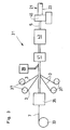
- Fig. 3 a Device for producing a optical element or optical cable.
- the optical example shown in FIG. 1 Element 1, which is particularly for use in Power cables or overhead line cables are suitable, e.g. B. twelve optical fibers 3 on that of a tubular Envelope 5 are enclosed.
- the z. B. with a thixotropic Gel-filled tubular casing 5 is made of a longitudinal, for example from a stainless Stainless steel existing metal band 7 formed that too a tube is formed and its band edges 9 and 11 overlap in an area 13.
- the band edge 9 of the Metal strip 7 is in the area 13 of the overlap its side 15 facing the band edge 11 with a Adhesive layer 17 provided, for example, from a can be melted even at low temperatures Hot melt adhesive exists.
- the adhesive layer 17 is the adhesive layer 17, for example, according to the Forming the metal strip 7 to the tube along the overlapping area 13 heated briefly while doing so the hot melt adhesive of the adhesive layer 17 in the brought molten state.
- the overlapping Band edges 9 and 11 are until the cooling of the Hot melt adhesive pressed together so that after the The hot melt adhesive hardens to a solid and permanent one Adhesive connection between the two tape edges 9 and 11 is made.
- the area 13 of the overlap of the two Band edges 9 and 11 preferably about 5 to 20% of Circumference of tubular casing 5.
- the optical example shown in FIG. 2 Cable 21 differs from that in FIG. 1 illustrated optical element 1 essentially in that the tubular casing 5 forming Metal band 7 on its outside completely with a adhesive layer 17 consisting of a hot melt adhesive is provided.
- the tubular shell 5 is for example directly from a jacket 23 made of plastic enclosed. During the extrusion of the jacket 23 on the tubular shell 5 is the heat of extrusion Hot melt adhesive of the adhesive layer 17 in the molten Brought condition.
- the hot melt Adhesive layer 17 the abutting band edges 9 and 11 of the metal strip 7 firmly and securely together and the tubular one formed by the metal band 7 Envelope 5 with the applied immediately above it Coat 23.
- the optical cable 21 thus produced is suitable especially as a central core cable, the tubular Shell 5 together with the jacket 23 a layer jacket forms.
- FIG. 3 shows an example of a device 31 for Manufacture of an optical cable according to the invention or Elements.
- the metal strip 7 is from a supply spool 33 withdrawn and a first forming device 35 supplied, in which the metal strip 7 is approximately U-shaped Takes shape.
- the 37 wound optical fibers 3 and one from one Storage container 39 removed filling mass, for example a thixotropic gel, in the U-shaped metal band 7 introduced.
- a Application device 41 a melted by heat Hot melt adhesive applied to the metal band 7.
- the hot melt adhesive is only applied in the area where the band edges of the Overlap metal strip 7 later.
- the metal band 7 is formed into a tube, the overlapping and abutting band edges of the Metal strip 7 through the cooling and thereby curing hot melt adhesive firmly glued together will. Then the tubular is formed Shell 5 with the help of an extruder 45 with a jacket 23 enclosed in plastic so that a central core optical cable 21 results.
Landscapes
- Physics & Mathematics (AREA)
- Engineering & Computer Science (AREA)
- Manufacturing & Machinery (AREA)
- General Physics & Mathematics (AREA)
- Optics & Photonics (AREA)
- Communication Cables (AREA)
- Insulated Conductors (AREA)
Applications Claiming Priority (2)
| Application Number | Priority Date | Filing Date | Title |
|---|---|---|---|
| DE1997113306 DE19713306C1 (de) | 1997-03-29 | 1997-03-29 | Optisches Element oder optisches Kabel und Verfahren zu dessen Herstellung |
| DE19713306 | 1997-03-29 |
Publications (2)
| Publication Number | Publication Date |
|---|---|
| EP0867741A2 true EP0867741A2 (fr) | 1998-09-30 |
| EP0867741A3 EP0867741A3 (fr) | 1999-10-20 |
Family
ID=7825056
Family Applications (1)
| Application Number | Title | Priority Date | Filing Date |
|---|---|---|---|
| EP98400512A Ceased EP0867741A3 (fr) | 1997-03-29 | 1998-03-03 | Elément optique ou càble optique et procédé de sa fabrication |
Country Status (3)
| Country | Link |
|---|---|
| EP (1) | EP0867741A3 (fr) |
| CN (1) | CN1195112A (fr) |
| DE (1) | DE19713306C1 (fr) |
Families Citing this family (4)
| Publication number | Priority date | Publication date | Assignee | Title |
|---|---|---|---|---|
| DE19900944A1 (de) * | 1999-01-13 | 2000-07-20 | Alcatel Sa | Optisches Kabel für die Verlegung in Abwasserkanälen |
| DE10035268A1 (de) * | 2000-07-20 | 2002-01-31 | Scc Special Comm Cables Gmbh | Optisches Kabel und Kanal- oder Rohrsystem mit einem installierten optischen Kabel |
| US6973245B2 (en) * | 2003-12-30 | 2005-12-06 | Furukawa Electric North America | Optical fiber cables |
| CN111913261A (zh) * | 2020-08-26 | 2020-11-10 | 江苏亨通海洋光网系统有限公司 | 一种光单元纵包铜带结构的海光缆及其制备方法 |
Citations (5)
| Publication number | Priority date | Publication date | Assignee | Title |
|---|---|---|---|---|
| EP0023154A1 (fr) * | 1979-07-23 | 1981-01-28 | PIRELLI GENERAL plc | Câble de fibres optiques et procédé pour sa fabrication |
| GB2138965A (en) * | 1983-04-25 | 1984-10-31 | Int Standard Electric Corp | Optical fibre cable and method of manufacture |
| US4679898A (en) * | 1984-09-18 | 1987-07-14 | N.K.F. Groep B.V. | Signal transmission cable |
| EP0306204A1 (fr) * | 1987-08-27 | 1989-03-08 | AT&T Corp. | Câble à fibre optique pour application dans un environnement à haute température |
| DE4336643A1 (de) * | 1993-10-22 | 1995-04-27 | Siemens Ag | Lichtwellenleiterelement mit polymerer Lichtleitfaser |
Family Cites Families (1)
| Publication number | Priority date | Publication date | Assignee | Title |
|---|---|---|---|---|
| DE4228271A1 (de) * | 1992-08-26 | 1994-03-03 | Siemens Ag | Verfahren und Einrichtung zur Herstellung eines optischen Kabels |
-
1997
- 1997-03-29 DE DE1997113306 patent/DE19713306C1/de not_active Expired - Fee Related
-
1998
- 1998-03-03 EP EP98400512A patent/EP0867741A3/fr not_active Ceased
- 1998-03-27 CN CN98105158A patent/CN1195112A/zh active Pending
Patent Citations (5)
| Publication number | Priority date | Publication date | Assignee | Title |
|---|---|---|---|---|
| EP0023154A1 (fr) * | 1979-07-23 | 1981-01-28 | PIRELLI GENERAL plc | Câble de fibres optiques et procédé pour sa fabrication |
| GB2138965A (en) * | 1983-04-25 | 1984-10-31 | Int Standard Electric Corp | Optical fibre cable and method of manufacture |
| US4679898A (en) * | 1984-09-18 | 1987-07-14 | N.K.F. Groep B.V. | Signal transmission cable |
| EP0306204A1 (fr) * | 1987-08-27 | 1989-03-08 | AT&T Corp. | Câble à fibre optique pour application dans un environnement à haute température |
| DE4336643A1 (de) * | 1993-10-22 | 1995-04-27 | Siemens Ag | Lichtwellenleiterelement mit polymerer Lichtleitfaser |
Also Published As
| Publication number | Publication date |
|---|---|
| EP0867741A3 (fr) | 1999-10-20 |
| CN1195112A (zh) | 1998-10-07 |
| DE19713306C1 (de) | 1998-04-23 |
Similar Documents
| Publication | Publication Date | Title |
|---|---|---|
| DE2701631C2 (de) | Optisch leitendes Element | |
| DE4142047C2 (de) | Verfahren zum Umhüllen mindestens eines Lichtwellenleiters mit einer Schutzschicht und zum Anbringen von Verstärkungselementen | |
| EP0874262A2 (fr) | Câble optique et procédé de fabrication d'un câble optique | |
| EP0025229B1 (fr) | Connexion à épissure pour câble guide d'ondes lumineuses tubulaires | |
| WO2009040271A2 (fr) | Élément de protection, manchon et guide d'ondes optiques, et procédé permettant de protéger une connexion entre au moins deux guide d'ondes optiques | |
| DE2701704A1 (de) | Verfahren zur herstellung eines optisch leitenden elements zum einbau in optische leiter | |
| DE69935637T2 (de) | Faseroptische Spleiß-Schutzvorrichtung und Verfahren zu deren Anwendung | |
| DE3227660C2 (de) | Verfahren zum Verbinden beschichteter, optischer Fasern | |
| DE3537553C2 (de) | Optisches Kabel mit mehreren Hauptbündeln | |
| DE3144851A1 (de) | Kabel und verfahren zu seiner herstellung | |
| EP0908749A1 (fr) | Elément optique comportant des unités collées | |
| DE19713306C1 (de) | Optisches Element oder optisches Kabel und Verfahren zu dessen Herstellung | |
| DE3330096C2 (fr) | ||
| DE2930643A1 (de) | Huelle fuer optische fasern | |
| EP0846970A1 (fr) | Procédé et dispositif pour la fabrication d'un bundle optique ou d'un câble optique | |
| DE3940414A1 (de) | Zugfeste verbindung zwischen zwei lichtwellenleiterkabeln | |
| DE3637812C2 (fr) | ||
| DE19818453A1 (de) | Lichtleiterschutz | |
| DE4412374A1 (de) | Lichtwellenleiterkabel mit zug- und stauchfesten Bündeladern | |
| DE4126464C2 (de) | Muffe, für bewehrte Kabel, vorzugsweise Lichtwellenleiterkabel | |
| DE9003135U1 (de) | Elektrisches oder optisches Kabel mit Reißfäden | |
| DE3342274C2 (fr) | ||
| DE3822543C2 (de) | Verfahren zum Herstellen eines gefüllten Kabels | |
| DE3830637C1 (en) | Method for repairing damaged loosely buffered optical fibres (waveguides) | |
| DE3639237C2 (fr) |
Legal Events
| Date | Code | Title | Description |
|---|---|---|---|
| PUAI | Public reference made under article 153(3) epc to a published international application that has entered the european phase |
Free format text: ORIGINAL CODE: 0009012 |
|
| AK | Designated contracting states |
Kind code of ref document: A2 Designated state(s): CH DE ES FR GB IT LI |
|
| AX | Request for extension of the european patent |
Free format text: AL;LT;LV;MK;RO;SI |
|
| RAP1 | Party data changed (applicant data changed or rights of an application transferred) |
Owner name: ALCATEL |
|
| PUAL | Search report despatched |
Free format text: ORIGINAL CODE: 0009013 |
|
| AK | Designated contracting states |
Kind code of ref document: A3 Designated state(s): AT BE CH DE DK ES FI FR GB GR IE IT LI LU MC NL PT SE |
|
| AX | Request for extension of the european patent |
Free format text: AL;LT;LV;MK;RO;SI |
|
| 17P | Request for examination filed |
Effective date: 19990929 |
|
| 17Q | First examination report despatched |
Effective date: 20000208 |
|
| AKX | Designation fees paid | ||
| REG | Reference to a national code |
Ref country code: DE Ref legal event code: 8566 |
|
| RBV | Designated contracting states (corrected) |
Designated state(s): CH DE ES FR GB IT LI |
|
| STAA | Information on the status of an ep patent application or granted ep patent |
Free format text: STATUS: THE APPLICATION HAS BEEN REFUSED |
|
| 18R | Application refused |
Effective date: 20020406 |