EP0867283B1 - Verfahren zur Herstellung von Bildern mit gleichmässiger Druckdichte - Google Patents
Verfahren zur Herstellung von Bildern mit gleichmässiger Druckdichte Download PDFInfo
- Publication number
- EP0867283B1 EP0867283B1 EP98200818A EP98200818A EP0867283B1 EP 0867283 B1 EP0867283 B1 EP 0867283B1 EP 98200818 A EP98200818 A EP 98200818A EP 98200818 A EP98200818 A EP 98200818A EP 0867283 B1 EP0867283 B1 EP 0867283B1
- Authority
- EP
- European Patent Office
- Prior art keywords
- nozzle
- nozzles
- density
- voltage pulse
- Prior art date
- Legal status (The legal status is an assumption and is not a legal conclusion. Google has not performed a legal analysis and makes no representation as to the accuracy of the status listed.)
- Expired - Lifetime
Links
Images


Classifications
-
- B—PERFORMING OPERATIONS; TRANSPORTING
- B41—PRINTING; LINING MACHINES; TYPEWRITERS; STAMPS
- B41J—TYPEWRITERS; SELECTIVE PRINTING MECHANISMS, i.e. MECHANISMS PRINTING OTHERWISE THAN FROM A FORME; CORRECTION OF TYPOGRAPHICAL ERRORS
- B41J2/00—Typewriters or selective printing mechanisms characterised by the printing or marking process for which they are designed
- B41J2/005—Typewriters or selective printing mechanisms characterised by the printing or marking process for which they are designed characterised by bringing liquid or particles selectively into contact with a printing material
- B41J2/01—Ink jet
- B41J2/015—Ink jet characterised by the jet generation process
- B41J2/04—Ink jet characterised by the jet generation process generating single droplets or particles on demand
- B41J2/045—Ink jet characterised by the jet generation process generating single droplets or particles on demand by pressure, e.g. electromechanical transducers
- B41J2/04501—Control methods or devices therefor, e.g. driver circuits, control circuits
- B41J2/0458—Control methods or devices therefor, e.g. driver circuits, control circuits controlling heads based on heating elements forming bubbles
-
- B—PERFORMING OPERATIONS; TRANSPORTING
- B41—PRINTING; LINING MACHINES; TYPEWRITERS; STAMPS
- B41J—TYPEWRITERS; SELECTIVE PRINTING MECHANISMS, i.e. MECHANISMS PRINTING OTHERWISE THAN FROM A FORME; CORRECTION OF TYPOGRAPHICAL ERRORS
- B41J2/00—Typewriters or selective printing mechanisms characterised by the printing or marking process for which they are designed
- B41J2/005—Typewriters or selective printing mechanisms characterised by the printing or marking process for which they are designed characterised by bringing liquid or particles selectively into contact with a printing material
- B41J2/01—Ink jet
- B41J2/015—Ink jet characterised by the jet generation process
- B41J2/04—Ink jet characterised by the jet generation process generating single droplets or particles on demand
- B41J2/045—Ink jet characterised by the jet generation process generating single droplets or particles on demand by pressure, e.g. electromechanical transducers
- B41J2/04501—Control methods or devices therefor, e.g. driver circuits, control circuits
- B41J2/04588—Control methods or devices therefor, e.g. driver circuits, control circuits using a specific waveform
-
- B—PERFORMING OPERATIONS; TRANSPORTING
- B41—PRINTING; LINING MACHINES; TYPEWRITERS; STAMPS
- B41J—TYPEWRITERS; SELECTIVE PRINTING MECHANISMS, i.e. MECHANISMS PRINTING OTHERWISE THAN FROM A FORME; CORRECTION OF TYPOGRAPHICAL ERRORS
- B41J2/00—Typewriters or selective printing mechanisms characterised by the printing or marking process for which they are designed
- B41J2/005—Typewriters or selective printing mechanisms characterised by the printing or marking process for which they are designed characterised by bringing liquid or particles selectively into contact with a printing material
- B41J2/01—Ink jet
- B41J2/015—Ink jet characterised by the jet generation process
- B41J2/04—Ink jet characterised by the jet generation process generating single droplets or particles on demand
- B41J2/045—Ink jet characterised by the jet generation process generating single droplets or particles on demand by pressure, e.g. electromechanical transducers
- B41J2/04501—Control methods or devices therefor, e.g. driver circuits, control circuits
- B41J2/04593—Dot-size modulation by changing the size of the drop
-
- B—PERFORMING OPERATIONS; TRANSPORTING
- B41—PRINTING; LINING MACHINES; TYPEWRITERS; STAMPS
- B41J—TYPEWRITERS; SELECTIVE PRINTING MECHANISMS, i.e. MECHANISMS PRINTING OTHERWISE THAN FROM A FORME; CORRECTION OF TYPOGRAPHICAL ERRORS
- B41J2/00—Typewriters or selective printing mechanisms characterised by the printing or marking process for which they are designed
- B41J2/005—Typewriters or selective printing mechanisms characterised by the printing or marking process for which they are designed characterised by bringing liquid or particles selectively into contact with a printing material
- B41J2/01—Ink jet
- B41J2/135—Nozzles
- B41J2/14—Structure thereof only for on-demand ink jet heads
- B41J2/14451—Structure of ink jet print heads discharging by lowering surface tension of meniscus
Definitions
- the present invention relates generally to imaging apparatus and methods and, more particularly, to an imaging apparatus and method for providing images of uniform print density, so that printing non-uniformities, such as banding, are avoided.
- digital signals as to each of four colors (i.e., red, green, blue and black) regarding an image are processed in a manner so that the multi-nozzle head forms a printed color image on a recorder medium, such as paper or transparency.
- ink jet printing has become recognized as a prominent contender in the digitally controlled, electronic printing arena because of its non-impact, low-noise characteristics, its use of plain paper and its avoidance of toner transfers and fixing.
- U.S. Pat. No. 4,275,290 which issued to Peolo Cielo et al. on June 23, 1981, discloses a liquid ink printing system in which ink is supplied to a reservoir at a predetermined pressure and retained in orifices by surface tension until the surface tension is reduced by heat from an electrically energized resistive heater.
- the heater causes ink to issue from the orifice and to thereby contact a paper receiver.
- This system requires that ink be designed so as to exhibit a change, preferably large, in surface tension with temperature.
- the paper receiver must also be in close proximity to the orifice in order to separate the drop from the orifice.
- ink jet printers may produce non-uniform print density with respect to the image deposited on the recorder medium. Such non-uniform print density may be visible as so-called “banding". "Banding” is evinced, for example, by repeated variations in the print density caused by delineations in individual dot rows comprising the output image. Thus, “banding” can appear as light or dark streaks or lines within a printed area. "Banding” is influenced by factors such as ink drop volume variations, print head carriage motion anomalies, electrical resistance variation of the heaters, and/or the presence of damaged nozzles.
- nozzle diameter also affects the meniscus shape of the ink at the nozzle's orifice, which in turn affects droplet volume and ejection rate.
- heater electrical resistance can vary among nozzles due to slight variations in the composition of the material comprising the electric resistance heaters disposed in the nozzles. Variations in electrical resistance among nozzles causes variations in the amount and ejection speed of the ink thereby leading to variations in print density. All the afore mentioned factors negatively affect print density and invite "banding". Therefore, a problem in the art is non-uniform print density due to the presence of physical variations among the print nozzles, such as variations in nozzle diameter and electrical resistance.
- the Ichikawa patent discloses that image processing is required for correcting density non-uniformities for each input image file. That is, image processing is required for each and every input image for which output density correction is desired. Correcting density non-uniformities for each input image file is undesirable because it is time consuming. Also, this patent discloses that modulation in the output code value is made at a relatively limited number of discrete levels for halftoned images at a typical printing resolution (i.e., 600 dots per inch). However, printing at discrete levels may not eliminate visual printing defects, such as "banding".
- W0-A-96 32289 discloses an imaging method involving use of a printhead that includes a plurality of nozzles each defining a fluid cavity containing print fluid under pressure.
- the nozzles each terminate in an outlet wherein a meniscus of the print fluid has a predetermined surface tension that is changed in response to heat.
- Heater elements in heat transfer communication with the print fluid menisci heat the print fluid menisci so that the surface tension of the print fluid menisci relax as the heater elements heat the print fluid menisci.
- Each of the heater elements is adapted to receive a predetermined voltage pulse.
- a voltage supply unit is associated with the heater elements and supplies the respective predetermined voltage pulses to the heater elements to generate heat sufficient to reduce surface tension of each respective meniscus so that the print fluid in the meniscus extends out further but such extension is insufficient to over overcome the surface tension to separate from the body of ink.
- the formation of a droplet is accomplished through close proximity of the receiver medium to the nozzle opening which effectively wicks or otherwise attracts a droplet onto the receiver medium. There is no description in D1 of free drops being created.
- EP-A-0 709 213 is directed to a method for correcting printhead non-uniformity involving print heads that employ bubble-jet action to eject a drop.
- Bubble-jet printing is characterized by creation of a bubble or significant void in the ink, the generation of which and the collapse of which causes a drop to be ejected from the nozzle.
- a known problem with bubble jet printing is that occasionally nozzles may be blocked through coalescence of bubbles thus creating imaging artifacts.
- EPA-0 609 997 is directed to an inkjet printer that includes a print head having firing thermal resistors responsive to groups of firing pulses. Rapid heating of the resistors causes the ink directly adjacent a thermal resistor to vaporize to form a bubble.
- this reference is also directed to a bubble-jet type of printer that is characterized by excessive heating and significant void formation which increases the likelihood of blockage of the nozzles and resultant imaging artifacts.
- the object of the present invention is to provide a suitable imaging method for providing images of uniform print density produced by print nozzles, so that printing non-uniformities, such as banding, are avoided, even when the print nozzles have different physical attributes resulting in different printing characteristics.
- the invention resides in an imaging method according to claim 1.
- Embodiments of the present invention are defined in claims 2 to 4.
- An advantage of the present invention is that images of uniform print density are provided even in the presence of variations in such factors as electrical resistance of the heater and/or diameter of the nozzle orifice.
- Another advantage of the present invention is that images of uniform print density are produced in a more time efficient manner compared to prior art techniques.
- a further advantage of the present invention is that use thereof eliminates visual printing defects, such as "banding".
- Imaging apparatus 10 having a uniform image forming characteristic for producing an output image lacking printing defects such as "banding".
- the image forming characteristic is print density.
- Imaging apparatus 10 comprises a printer, generally referred to as 20, electrically connected to an input source 30 for reasons disclosed hereinbelow.
- Input source 30 may provide raster image data from a scanner or computer, outline image data in the form of a page description language, or other form of digital image data.
- the output signal generated by input source 30 is received by a controller 40, for reasons disclosed in detail hereinbelow.
- controller 40 processes the output signal generated by input source 30 and generates a controller output signal that is received by a print head 45 capable of printing on a recorder medium 50.
- recorder medium 50 may be fed past print head 45 at a predetermined feed rate by a plurality of rollers 60 (only some of which are shown). That is, recorder medium 50 may be fed, by rollers 60, from an input supply tray 70 containing a supply of recorder medium 50.
- Controller 40 in turn communicates that line of image information to print head 45 as recorder medium 50 is fed past print head 45.
- print head 45 When a completely printed image is formed on recorder medium 50, recorder medium 50 exits the interior of printer 20 to be deposited in an output tray 80 for retrieval by an operator of imaging apparatus 10.
- print head 45 is intended to also include its plural form because there may be, for example, four print heads 110, each one of the print heads 110 being respectively dedicated to printing one of four colors (i.e., red, green, blue and black).
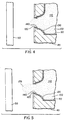
- print head 45 which belongs to printer 20, is there shown in operative condition for printing an image on recorder medium 50.
- Print head 45 comprises a plurality of ink fluid cavities 90 for holding print fluid, such as a body of ink 100.
- Each cavity 90 is in communication with a print fluid reservoir 110 for supplying ink 100 into cavity 90.
- a nozzle 120 associated with each cavity 90 is a nozzle 120 for allowing ink 100 to exit cavity 90.
- each nozzle 120 includes a flow channel 130 and a generally circular orifice portion 140 in communication with flow channel 130.
- Orifice portion 140 which is disposed proximate recorder medium 50, opens toward recorder medium 50 for depositing ink 100 onto recorder medium 50.
- lining orifice portion 140 and flow channel 130 is a generally annular electrothermal actuator (i.e., an electrical resistance heater element) 150 for heating ink 100, heater 150 having a predetermined electrical resistance.
- each heater 150 is in heat transfer communication with ink 100.
- a voltage supply unit 160 is electrically connected to print head 45 for supplying a voltage pulse to each heater 150.
- Each nozzle 120 has an image forming characteristic (e.g., print density) associated therewith. As described more fully hereinbelow, the voltage pulse is capable of altering the image forming characteristic to define an altered image forming characteristic. Controller 40 controls the voltage pulse so that the altered image forming characteristics for all nozzles 120 are uniform.
- This heating of ink 100 results in a localized decrease in surface tension of droplet 170.
- the surface tension of droplet 170 decreases, it assumes a substantially cylindrical form due to a surface tension gradient from the tip of orifice region 140 to the center of droplet 170, and due to viscous drag or flow resistance along the surface of flow channel 130 and orifice region 140.
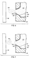
- Fig. 7 shows droplet 170 separated from ink body 100 and ejected from orifice region 140 as it is propelled outwardly toward recorder medium 50 to establish an ink mark upon recorder medium 50.
- Droplet 170 will eventually be intercepted by recorder medium 50 to "soak into” and be absorbed by recorder medium 50.
- each resistance heater 150 may be selectively energized many times by voltage supply unit 160 to deposit a multiplicity of ink marks upon recorder medium 50 in a predetermined pattern according to the image file residing in input source 30.
- the image printed onto recorder medium 50 should possess a uniform print density to avoid "banding".
- banding is a recurring problem in the printing arts. Often “banding” (i.e., print density non-uniformity) results from variability in the print head fabrication process. For example, banding can be caused by variability in the diameter of orifice region 140 due to variations in the manufacturing process used to make nozzle 120 or by variability in electrical resistance among resistance heaters 150 due to slight variations in the chemical composition comprising heaters 150. Even small variations in diameter and electrical resistance can lead to visible "banding". Therefore, a long-standing problem experienced in the art is banding, which may be caused by the presence of physical variations among individual print nozzles 120.
- the present invention controls the voltage pulse amplitude or, alternatively, the voltage pulse duration supplied to each heater 150 to compensate for physical anomalies (e.g., variations in the diameter of orifice region 140, and/or variations in electrical resistance of heaters 150) associated with individual nozzles 120. Controlling the voltage pulse in this manner obtains uniform print density on recorder medium 150. This result is attainable because controlling the voltage pulse amplitude and/or voltage pulse duration supplied to each nozzle 120 controls the surface tension of ink droplet 170, which in turn controls the rate and the volume of ink released from each nozzle 120. Controlling the rate and volume of ink released from each nozzle 120 controls the print density provided by each nozzle 120.
- physical anomalies e.g., variations in the diameter of orifice region 140, and/or variations in electrical resistance of heaters 150
- nozzles 120 are calibrated such that each nozzle 120 will selectively receive a predetermined pulse voltage amplitude or pulse voltage duration as print head 45 is operated in order that print densities for all nozzles 120 are substantially the same (i.e., uniform), even though physical attributes among nozzles 120 may vary.
- the volume of ink 100 ejected by print head 45 is a function of the amplitude and duration of the voltage pulse supplied to print head 45. Larger droplets 170 with larger volumes of ink will cause higher density images on recorder medium 50. Conversely, smaller droplets 170 with smaller volumes of ink will cause lower density images on recorder medium 50.
- print density is a function of the amplitude and the duration of the electric pulse received by print head 45 because the volume of ink released is a function of the amplitude and duration of the voltage pulse.
- D f (V p , T)
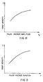
- Equation (1) provides print density for print head 45, taken as a whole, and is illustrated graphically for print head 45 in Figs. 8 and 9.
- print density D is shown as a function of voltage pulse amplitude V p while holding the voltage pulse duration T constant.
- print density D is shown as a function of voltage pulse duration T while holding the voltage pulse amplitude V p constant.
- the precise functional dependence of print density D upon voltage pulse amplitude V p and voltage pulse duration T as illustrated by Figs. 8 and 9, respectively, is obtainable by a process that includes measuring print density D of a uniform test image printed by the relatively large number of nozzles 120 of print head 45, as described more fully hereinbelow.
- Test image 180 includes a plurality of "density patches" 190 having print densities D varying from a minimum print density D l (i.e., near white or light halftone) to a maximum print density D w .
- the print densities D for each of the density patches 190 is preferably measured by use of a densitometer (not shown) which scans a generally circular print area (e.g., approximately 0.20 square centimeters) of each density patch 190.
- the densitometer is used to scan many different areas of each density patch 190. These multiple densitometer readings are averaged to provide an averaged density value for each density patch 190.
- a separate test image 180 is produced at each of a plurality of voltage pulse amplitudes while keeping the voltage pulse duration constant. Also, a separate test image 180 is produced at each of a plurality of voltage pulse durations while keeping the voltage pulse amplitude constant. This process results in a multiplicity of print density measurements because measurement of print density using the densitometer is repeated for each density patch 190 of each test image 180. Moreover, the foregoing process is repeated for each of the print heads 110 (e.g., for each of the print heads corresponding to each of the colors red, green, blue and black).
- Equation (1) the precise function shown in Equation (1) for print head 45 is obtained by mathematical means well known in the art, such as by means of statistical curve-fitting procedures. Using this precise function provides print density D as a function of V p , which is plotted in Fig. 8. Also using this precise function provides print density D as a function of T, which is plotted in Fig. 9. However, it should be appreciated that Figs. 8 and 9 show print density D of print head 45 taken as a whole and does not provide print density of individual nozzles 120. In other words, Equation (1), from which Figs. 8 and 9 are plotted, provides a functional relationship defining an aggregate print density for print head 45, as whole.
- print density among nozzles 120 may vary due, for example, to variations in nozzle orifice diameter and/or electrical resistance of heaters 150. It is therefore desirable to calibrate nozzles 120, so that all nozzles 120 of print head 45 print with uniform print density, even though physical attributes among nozzles 120 may vary.
- either of two techniques may be used to provide uniform print density of individual nozzles 120 in view of the unique physical attributes associated with each nozzle 120. These two techniques are defined herein as the “Resistance Calibration Technique” and the “Density Calibration Technique” and are described in detail hereinbelow. Resistance Calibration Technique:
- a square wave voltage pulse 210 of constant voltage amplitude V pi is sequentially applied to each heater 150 associated with each nozzle 120. That is, constant voltage pulse 210 is sequentially applied to each heater 150 from the first heater 150 to the last heater 150 in print head 45.
- the last heater 150 is represented as heater number "N" in Fig. 13.
- the output voltage is measured at each heater 150 and a resistance R i is calculated for each heater 150.
- V pi is the voltage pulse amplitude to be applied to the "i th " nozzle 120 in order for the print density of the "i th " nozzle 120 to be equal to the print density D of print head 45.
- voltage amplitude V pi for each nozzle 120 is selected such that print density of each nozzle 120 matches the desired aggregate print density value for print head 45, as a whole. In this manner, nozzles 120 will print with uniform print density because each nozzle 120 will print with the print density D of print head 45.
- the voltage pulse duration of the square wave voltage pulse 210 may be used to calibrate each heater 150 in order to provide uniform print density.
- Equation (5) provides the voltage pulse amplitude V pi or alternatively Equation (7) provides the voltage pulse duration T i to be applied to each nozzle 110 in order to calibrate each heater 150 ( i.e., each nozzle 120) so that all nozzles 120 provide uniform print density even though electrical resistances among heaters 150 may vary.
- calibration of each heater 150 (i.e., each nozzle 120) using the Resistance Calibration Technique compensates for variabilities only in electrical resistance among individual heaters 150 (i.e., among individual nozzles 120).
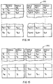
- V pi and T i are stored electronically in a memory unit, such as a Read-Only-Memory (ROM) semiconductor computer chip 220 connected to controller 40.
- ROM Read-Only-Memory
- the values of D, V pi , and T i stored in chip 220 are represented herein as first and second look-up tables, generally referred to as 230 and 240, respectively.
- the values of D, V pi , and T i stored in chip 220 are used as parameters for each nozzle 120 during normal operation of apparatus 10, as described in more detail hereinbelow. More specifically, during normal operation of apparatus 10, the desired print density D is selected, such as by means of input source 30, and is then communicated to controller 40. Once controller 40 accepts density value D to be printed by print head 45, controller 40 is informed by first lookup table 230 in chip 220 as to the correct voltage amplitude V pi to apply to each nozzle 120 in order to obtain uniform print density D from each nozzle 120. In this case, only first look-up table 230 is stored in chip 220. This is so because pulse voltage duration T is held at a constant value by controller 40 and, therefore, there is no need to store second look-up table 240 in chip 220.
- controller 40 accepts a density value D to be printed by print head 45, controller 40 is informed by second lookup table 240 stored in chip 220 as to the correct voltage pulse duration T i to apply to each nozzle 120 in order to obtain uniform print density D from each nozzle 120.
- second look-up table 240 is stored in chip 220. This is so because the pulse voltage amplitude V p is held at a constant value by controller 40 and, therefore, there is no need to store first look-up table 230 in chip 220.
- each heater 150 i.e., nozzle 120 belonging to print head 45 is calibrated merely by supplying the square wave voltage pulse 210 illustrated by Fig. 12 and measuring the resulting electrical resistance R i of each heater 150, as illustrated by Fig. 13. In this manner, each nozzle 120 can be conveniently calibrated during manufacture of print head 45. In addition, each nozzle 120 can be recalibrated, if necessary, "in the field" at a customer site to accommodate print head 45 to the specific environmental conditions (e.g., humidity, dust, temperature, e.t.c.) present at the customer's site. Such environmental conditions may have altered the original calibration of print head 45 performed during manufacture of print head 45.
- environmental conditions e.g., humidity, dust, temperature, e.t.c.
- nozzles 120 may be calibrated to compensate for physical characteristics in addition to electrical resistance.
- the present invention provides a technique, defined herein as the Density Calibration Technique, which compensates for variability in substantially all physical characteristics in addition to electrical resistance.
- the Density Calibration Technique calibrates nozzles 120 to compensate for substantially all variabilities among nozzles 120, including variabilities caused by different amounts of electrical resistance, in order to obtain uniform print density. This technique is described in detail hereinbelow.
- print head 45 to be calibrated is used to print the previously mentioned test image 180 in the manner described hereinabove.
- This produces print density patches D l to D w .
- the previously mentioned densitometer is then used to measure the resulting print densities in two directions (i.e., vertically and horizontally), preferably at a resolution of at least 300 dpi.
- the density values are integrated vertically down each density patch in order to obtain the one-dimensional density profile of Fig. 16.
- Fig. 16 characterizes print density non-uniformity due to physical variabilities among nozzles 120. It is understood that print density measurements are not taken in marginal region 200 for the reasons provided hereinabove.
- These print density values may be fit, by means well known in the art, to an analytical function so that the print density value for each nozzle 120 is conveniently obtained by reference merely to the analytical function.
- Equation (1) and Equation (8) differ to the extent that Equation (8) provides print density D i for each nozzle 120 (in order to consider differences in physical characteristics among nozzles 120) and Equation (1) provides a print density D for print head 45 as a whole (and thus does not consider differences among nozzles 120).
- Equation (1) demonstrates that print head 45 will print with the ideal print density D only if each nozzle 120 prints with this same print density D.
- each nozzle 120 will not necessarily print with the same print density D due to variabilities found, for example, in the diameter of nozzle orifice portion 140 and/or the electrical resistance in heaters 150. Therefore, Equation (2) determines the print density D i for each "i th " nozzle 120.
- T i T + (D - D i ) / ( ⁇ f (V p , T) / ⁇ T).
- the first and second look-up tables 230/240 described hereinabove for the Resistance Calibration Technique are also constructed for the Density Calibration Technique.
- controller 40 accepts a density value D to be printed by print head 45, controller 40 is informed by first lookup table 230 in chip 220 as to the correct voltage amplitude V pi to apply to each nozzle 120 in order to obtain uniform print density D among nozzles 120.
- first look-up table 230 which contains the V pi values as a function of density D i , is stored in chip 220.
- pulse voltage duration T is held at a constant value by controller 40 and therefore, in this case, there is no need to store second look-up table 240 in chip 220.
- controller 40 accepts a density value D to be printed by print head 45, controller 40 is informed by second lookup table 240 stored in chip 220 as to the correct voltage pulse duration T i to apply to each nozzle 120 in order to obtain uniform print density D among nozzles 120.
- second look-up table 240 which contains the T i values as a function of density D i , is stored in chip 220.
- the pulse voltage amplitude V p is held at a constant value by controller 40 and therefore, in this case, there is no need to store first look-up table 230 in chip 220.
- print line time is defined herein to mean the time spent on marking each row of ink pixels on recorder medium 180. That is, when voltage pulse amplitude V pi is varied, the voltage pulse duration T is held constant among all nozzles 120 in print head 45 and the printing line time is set equal to or greater than the constant voltage pulse duration T. Alternatively, when voltage pulse duration T i is varied, the voltage pulse amplitude V p is held constant among all nozzles 120 in print head 45 and the printing line time is set equal to or greater than the maximum pulse duration allowable for nozzles 120.
- Fig. 17 presents a flow chart 250 summarizing selected steps in the method of the invention. More specifically, flow chart 250 illustrates steps for arriving at Equations (5), (7), (12) and (13). The steps of the Density Calibration technique described hereinabove calibrates nozzles 120 in such a manner that effectively all physical variations among nozzles 120 will be compensated for, in order to obtain uniform print density from nozzles 120.
- square wave form of voltage pulse 210 is preferably used in those cases where control of print head 45 is provided digitally. That is, square wave voltage pulse 210 is preferable in those cases where the digital signal supplied to print head 45 is either "1" (e.g., for "on") or "0" (e.g., for "off”).
- one constraint or limitation on the amount of heat energy "E" supplied to ink droplet 170 is that the temperature of ink droplet 170 is preferably kept below its boiling temperature, so that nozzles 120 will not be blocked by coalescence of bubbles.
- a different pulse wave form is substituted for the square wave form of Fig. 12 in order to mitigate formation of voids or bubbles.
- an analog wave form 260 may be used.
- Analog wave form 260 has a low voltage preheat region to warm-up ink droplet 170, a peak voltage, and then a logrithmically decreasing voltage region. Analog wave form 260 will allow ink droplet 170 to be released from nozzle 120 without excessive heating, so that significant void formation is precluded. It is understood that analog wave form 260 may be substituted for the square wave form 210, if desired.
- an advantage of the present invention is that images of uniform print density are provided even in the presence of variations in such factors as electrical resistance of the heaters and/or diameter of the nozzle orifice. This is so because each nozzle 120 is calibrated by means of either the Resistance Calibration Technique or by means of the Density Calibration Technique to compensate for such variability among nozzles 120.
- Another advantage of the present invention is that use thereof saves time because correcting print density non-uniformities for each input image file is not required. That is, image processing is not required for each and every input image for which output density correction is desired. This is so because print head 45 is preferably calibrated once, such as at manufacture, rather than each time an image file is acquired by input source 30.
- a further advantage of the present invention is that it eliminates visual printing defects, such as "banding". Of course, this is so because the print nozzles print with uniform density.
- the invention is described with reference to a scanner or computer being used to provide the input image.
- any suitable input imaging device may be used to provide the input image.
- the invention is described with reference to an ink-jet printer.
- the image forming characteristic is print density in the preferred embodiment of the invention.
- any applicable image forming characteristic may be selected, such as ink droplet volume.
- an imaging method for providing images of uniform print density, so that printing non-uniformities, such as banding, are avoided.
Landscapes
- Particle Formation And Scattering Control In Inkjet Printers (AREA)
- Ink Jet (AREA)
Claims (4)
- Verfahren zur Bilderzeugung mit folgenden Schritten:Bereitstellen einer Vielzahl von Düsen (120), von denen jede einen Flüssigkeits-hohlraum bildet, der unter Druck stehende Druckflüssigkeit enthält, wobei jede der Düsen mit einem Auslass abschließt, und wobei ein Meniskus der Druck-flüssigkeit eine vorbestimmte Oberflächenspannung aufweist, die sich wärme-abhängig ändert;Bereitstellen einer Vielzahl von in Wärmeübertragungskommunikation mit den Menisken der Druckflüssigkeit stehenden Heizelementen (150) und Erwärmen der Druckflüssigkeitsmenisken, so dass bei deren Erwärmung durch die Heizelemente die Oberflächenspannung der Menisken reduziert wird, wobei jedes der Heizelemente so ausgelegt ist, dass es einen vorbestimmten Spannungsimpuls empfangen kann;Bereitstellen einer Spannungsquelle (160), die den Heizelementen zugeordnet ist und den Heizelementen jeweils einen vorbestimmten Spannungsimpuls zuführt, wobei die den jeweiligen Heizelementen zugeführten Spannungsimpulse Wärme erzeugen, die ausreicht, die Oberflächenspannung der jeweiligen Menisken zu reduzieren, so dass der Überdruck der im Flüssigkeitshohlraum befindlichen Druckflüssigkeit diese als Tropfen aus dem Flüssigkeitshohlraum treibt und so zwischen den Düsen und dem Empfangsmedium ein freier Tropfen erzeugt wird, ohne dass in den Düsen die Bildung eines nennenswerten luftleeren Raums erfolgt; undBereitstellen eines Steuergeräts (40), welches die Heizelemente und die Spannungsquelle verbindet, und wobei das Steuergerät die den jeweiligen Heizelementen zugeführten Spannungsimpulse steuert, so dass die Steuerimpulse, welche einigen der Heizelemente zugeführt werden, die für die Bildung von Tropfen zum Drucken mit derselben Dichte und Farbe ausgewählt wurden, mit unterschiedlichen Amplituden und/oder unterschiedlicher Impulsdauer bereitgestellt werden, um Ungleichmäßigkeiten beim Betrieb der jeweiligen Düsen zu korrigieren, wobei das Steuergerät einen Speicher aufweist, der die den jeweiligen Düsen zugeordneten Kalibrationsdaten speichert, und wobei das Steuergerät in Abhängigkeit von den Bild- und Kalibrationsdaten arbeitet, um den jeweiligen Heizelementen Spannungsimpulse für die Erzeugung der entsprechenden Tropfen auf dem Empfangsmedium zuzuführen, die dann gleichförmig sind, wenn die Bilddaten für die jeweiligen Düsen denselben Dichtewert aufweisen.
- Verfahren nach Anspruch 1, dadurch gekennzeichnet, dass der Speicher Daten speichert, die in Bezug zu Impulsamplitudenwerten stehen, und dass er dem Steuergerät Daten bezüglich einer Impulsamplitude für eine zum Drucken durch eine Düse angeforderte Druckdichte übermittelt, und dass die Daten, die in Bezug zu Impulsamplitudenwerten stehen und dem Steuergerät, für zumindest einige der Düsen, in Abhängigkeit von Datenanforderungen übermittelt wurden, die für die Speichereinheit denselben Dichtewert darstellen, unterschiedlich sind, um dem Steuergerät Anweisungen für unterschiedliche Amplitudenwerte zukommen zu lassen, so dass Ungleichmäßigkeiten in den Düsen kompensiert werden können.
- Verfahren nach Anspruch 1 oder 2, dadurch gekennzeichnet, dass ein an ein Heizelement für die Erzeugung eines Tropfens abgegebener Spannungsimpuls einen Amplitudenteil aufweist, der sich zeitabhängig logarithmisch verändert.
- Verfahren nach Anspruch 1, dadurch gekennzeichnet, dass die Druckdichte jeder Düse durch die Dauer des Spannungsimpulses bestimmt wird, der an die jeweiligen, den Düsen zugeordneten Heizelemente abgegeben wird.
Applications Claiming Priority (2)
| Application Number | Priority Date | Filing Date | Title |
|---|---|---|---|
| US826353 | 1997-03-26 | ||
| US08/826,353 US6312078B1 (en) | 1997-03-26 | 1997-03-26 | Imaging apparatus and method of providing images of uniform print density |
Publications (3)
| Publication Number | Publication Date |
|---|---|
| EP0867283A2 EP0867283A2 (de) | 1998-09-30 |
| EP0867283A3 EP0867283A3 (de) | 1999-08-18 |
| EP0867283B1 true EP0867283B1 (de) | 2004-08-11 |
Family
ID=25246324
Family Applications (1)
| Application Number | Title | Priority Date | Filing Date |
|---|---|---|---|
| EP98200818A Expired - Lifetime EP0867283B1 (de) | 1997-03-26 | 1998-03-16 | Verfahren zur Herstellung von Bildern mit gleichmässiger Druckdichte |
Country Status (4)
| Country | Link |
|---|---|
| US (1) | US6312078B1 (de) |
| EP (1) | EP0867283B1 (de) |
| JP (1) | JPH10264371A (de) |
| DE (1) | DE69825514T2 (de) |
Families Citing this family (15)
| Publication number | Priority date | Publication date | Assignee | Title |
|---|---|---|---|---|
| US6536873B1 (en) * | 2000-06-30 | 2003-03-25 | Eastman Kodak Company | Drop-on-demand ink jet printer capable of directional control of ink drop ejection and method of assembling the printer |
| JP2004521784A (ja) * | 2001-04-04 | 2004-07-22 | エイプリオン・デジタル・リミテッド | インクジェット・プリンタのバンディング補償方法及びバンディング補償システム |
| US20030173716A1 (en) * | 2002-02-13 | 2003-09-18 | Pang-Chia Lu | Digital printing system for printing colored polyolefin films |
| KR100470579B1 (ko) * | 2002-11-02 | 2005-03-08 | 삼성전자주식회사 | 잉크젯 기록 장치의 제어장치 및 제어방법 |
| US6830306B2 (en) | 2003-05-06 | 2004-12-14 | Eastman Kodak Company | Compensating for drop volume variation in an inkjet printer |
| US7556337B2 (en) | 2006-11-02 | 2009-07-07 | Xerox Corporation | System and method for evaluating line formation in an ink jet imaging device to normalize print head driving voltages |
| GB0622789D0 (en) * | 2006-11-15 | 2006-12-27 | Cambridge Display Technology O | Droplet deposition method |
| GB0622784D0 (en) * | 2006-11-15 | 2006-12-27 | Cambridge Display Technology O | Droplet volume control |
| US20090135279A1 (en) * | 2007-11-26 | 2009-05-28 | Xerox Corporation | Reducing imaging artifacts caused by defective imaging element |
| US8414102B2 (en) | 2011-08-11 | 2013-04-09 | Xerox Corporation | In situ calibration of multiple printheads to reference ink targets |
| US8662616B2 (en) | 2011-11-08 | 2014-03-04 | Xerox Corporation | Method and system for adjusting printhead voltage parameters in an inkjet printer |
| US8851601B2 (en) | 2012-02-07 | 2014-10-07 | Xerox Corporation | System and method for compensating for drift in multiple printheads in an inkjet printer |
| JP6972824B2 (ja) * | 2017-09-20 | 2021-11-24 | 京セラドキュメントソリューションズ株式会社 | インクジェット記録装置 |
| JP7102878B2 (ja) * | 2018-04-04 | 2022-07-20 | 京セラドキュメントソリューションズ株式会社 | 記録ヘッドユニット及びインクジェット記録装置 |
| DE102019113267B4 (de) * | 2019-05-20 | 2021-04-22 | Koenig & Bauer Ag | Verfahren zum Betreiben einer Tintenstrahldruckmaschine mit zumindest einer Modifikationsfunktion |
Citations (1)
| Publication number | Priority date | Publication date | Assignee | Title |
|---|---|---|---|---|
| EP0609997A2 (de) * | 1993-02-05 | 1994-08-10 | Hewlett-Packard Company | Verfahren zur Reduzierung der Antriebsenergie in einem thermischen Tintenstrahlschnelldrucker |
Family Cites Families (23)
| Publication number | Priority date | Publication date | Assignee | Title |
|---|---|---|---|---|
| US3946398A (en) | 1970-06-29 | 1976-03-23 | Silonics, Inc. | Method and apparatus for recording with writing fluids and drop projection means therefor |
| CA1127227A (en) | 1977-10-03 | 1982-07-06 | Ichiro Endo | Liquid jet recording process and apparatus therefor |
| US4166277A (en) | 1977-10-25 | 1979-08-28 | Northern Telecom Limited | Electrostatic ink ejection printing head |
| US4275290A (en) | 1978-05-08 | 1981-06-23 | Northern Telecom Limited | Thermally activated liquid ink printing |
| JPS55131882A (en) | 1979-04-02 | 1980-10-14 | Canon Inc | Electronic equipment |
| US4490728A (en) | 1981-08-14 | 1984-12-25 | Hewlett-Packard Company | Thermal ink jet printer |
| US5172142A (en) | 1985-04-15 | 1992-12-15 | Canon Kabushiki Kaisha | Ink jet recording apparatus with driving means providing a driving signal having upper and lower limits in response to an input signal |
| US4746935A (en) | 1985-11-22 | 1988-05-24 | Hewlett-Packard Company | Multitone ink jet printer and method of operation |
| US4751531A (en) | 1986-03-27 | 1988-06-14 | Fuji Xerox Co., Ltd. | Thermal-electrostatic ink jet recording apparatus |
| JPH0729421B2 (ja) | 1987-04-24 | 1995-04-05 | 松下電器産業株式会社 | インクジエツトプリンタ |
| EP0317268B1 (de) | 1987-11-16 | 1997-07-23 | Canon Kabushiki Kaisha | Bildaufzeichnungsgerät |
| DE69033001T2 (de) | 1989-10-05 | 1999-09-09 | Canon Kk | Bilderzeugungsgerät |
| US4999646A (en) | 1989-11-29 | 1991-03-12 | Hewlett-Packard Company | Method for enhancing the uniformity and consistency of dot formation produced by color ink jet printing |
| JP2863241B2 (ja) * | 1990-02-02 | 1999-03-03 | キヤノン株式会社 | 記録ヘッドおよび記録ヘッド駆動方法 |
| EP0468075A1 (de) | 1990-07-26 | 1992-01-29 | Siemens Aktiengesellschaft | Verfahren zum Variieren der Tropfenmasse in Tintenschreibeinrichtungen |
| JP2950950B2 (ja) | 1990-08-31 | 1999-09-20 | キヤノン株式会社 | 画像記録装置 |
| US5412410A (en) | 1993-01-04 | 1995-05-02 | Xerox Corporation | Ink jet printhead for continuous tone and text printing |
| EP0649746A1 (de) | 1993-10-26 | 1995-04-26 | Hewlett-Packard Company | Tintenstrahldruckköpfe mit variablem Halbton-Betrieb |
| JPH07323578A (ja) | 1994-05-31 | 1995-12-12 | Canon Inc | 記録装置 |
| JP3174226B2 (ja) | 1994-10-28 | 2001-06-11 | キヤノン株式会社 | 記録ヘッド補正方法及びその装置及びその装置によって補正された記録ヘッド及びその記録ヘッドを用いた記録装置 |
| US5808639A (en) * | 1995-04-12 | 1998-09-15 | Eastman Kodak Company | Nozzle clearing procedure for liquid ink printing |
| AUPN232195A0 (en) | 1995-04-12 | 1995-05-04 | Eastman Kodak Company | Multiple simultaneous drop sizes in proximity lift printing |
| JPH0911463A (ja) | 1995-06-28 | 1997-01-14 | Fuji Xerox Co Ltd | インクジェット記録装置、インクジェット記録装置の駆動装置、インクジェット記録方法 |
-
1997
- 1997-03-26 US US08/826,353 patent/US6312078B1/en not_active Expired - Fee Related
-
1998
- 1998-03-16 EP EP98200818A patent/EP0867283B1/de not_active Expired - Lifetime
- 1998-03-16 DE DE69825514T patent/DE69825514T2/de not_active Expired - Fee Related
- 1998-03-26 JP JP10078971A patent/JPH10264371A/ja active Pending
Patent Citations (1)
| Publication number | Priority date | Publication date | Assignee | Title |
|---|---|---|---|---|
| EP0609997A2 (de) * | 1993-02-05 | 1994-08-10 | Hewlett-Packard Company | Verfahren zur Reduzierung der Antriebsenergie in einem thermischen Tintenstrahlschnelldrucker |
Also Published As
| Publication number | Publication date |
|---|---|
| DE69825514D1 (de) | 2004-09-16 |
| EP0867283A3 (de) | 1999-08-18 |
| DE69825514T2 (de) | 2005-09-01 |
| EP0867283A2 (de) | 1998-09-30 |
| JPH10264371A (ja) | 1998-10-06 |
| US6312078B1 (en) | 2001-11-06 |
Similar Documents
| Publication | Publication Date | Title |
|---|---|---|
| EP0867283B1 (de) | Verfahren zur Herstellung von Bildern mit gleichmässiger Druckdichte | |
| US5736995A (en) | Temperature control of thermal inkjet printheads by using synchronous non-nucleating pulses | |
| US6428134B1 (en) | Printer and method adapted to reduce variability in ejected ink droplet volume | |
| US5036337A (en) | Thermal ink jet printhead with droplet volume control | |
| KR0182631B1 (ko) | 프린팅 헤드 및 이를 보정하는 장치 및 방법 | |
| EP0658429B1 (de) | Steuerschaltung zur Regelung der Temperatur in einem Tintenstrahldruckkopf | |
| JP2010264761A (ja) | インクジェットによるプリント方法 | |
| EP1987959B1 (de) | Einstellungsverfahren für Streifenbildung für mehrere Druckköpfe | |
| US9862187B1 (en) | Inkjet printhead temperature sensing at multiple locations | |
| JPH11320884A (ja) | インクジェットプリントカ―トリッジのエネルギ―制御法 | |
| JPH10138509A (ja) | 記録ヘッド補正方法及びその装置及びその装置によって補正された記録ヘッド及びその記録ヘッドを用いた記録装置 | |
| US6464320B1 (en) | Recording head and recording apparatus using the same | |
| JPH06166247A (ja) | 記録濃度むら補正機能を有する記録装置および記録濃度むら補正方法 | |
| JPH09187970A (ja) | 入力ディジタルグレースケール画像の印刷方法 | |
| JP2004074510A (ja) | 記録装置及びテストパターン記録方法 | |
| US5673069A (en) | Method and apparatus for reducing the size of drops ejected from a thermal ink jet printhead | |
| KR0167731B1 (ko) | 프린트헤드 보정 장치, 프린트헤드 및 이를 사용한 프린팅 장치, 및 프린트헤드 보정방법 | |
| US9981465B1 (en) | Inkjet printing apparatus with firing or heating waveform selector | |
| US5483265A (en) | Minimization of missing droplets in a thermal ink jet printer by drop volume control | |
| JPH07242004A (ja) | プリントヘッド及びその製造装置及び製造方法及びプリント装置 | |
| US6109732A (en) | Imaging apparatus and method adapted to control ink droplet volume and void formation | |
| EP0867284A2 (de) | Bilderzeugungsgerät und angepasstes Verfahren zur Regelung des Volumes von Tintentröpfchen und der Bläschenerzeugung | |
| JP3062387B2 (ja) | 記録ヘッド及び該記録ヘッドを用いた記録方法及び装置 | |
| JPH09104111A (ja) | インクジェット記録装置 | |
| EP0600648B1 (de) | Verfahren und Vorrichtung zur Überwachung von Thermo-Tintenstrahl-Druckern |
Legal Events
| Date | Code | Title | Description |
|---|---|---|---|
| PUAI | Public reference made under article 153(3) epc to a published international application that has entered the european phase |
Free format text: ORIGINAL CODE: 0009012 |
|
| AK | Designated contracting states |
Kind code of ref document: A2 Designated state(s): DE FR GB |
|
| AX | Request for extension of the european patent |
Free format text: AL;LT;LV;MK;RO;SI |
|
| RIN1 | Information on inventor provided before grant (corrected) |
Inventor name: WEN, XIN, C/O EASTMAN KODAK COMPANY |
|
| PUAL | Search report despatched |
Free format text: ORIGINAL CODE: 0009013 |
|
| AK | Designated contracting states |
Kind code of ref document: A3 Designated state(s): AT BE CH DE DK ES FI FR GB GR IE IT LI LU MC NL PT SE |
|
| AX | Request for extension of the european patent |
Free format text: AL;LT;LV;MK;RO;SI |
|
| 17P | Request for examination filed |
Effective date: 19991211 |
|
| AKX | Designation fees paid |
Free format text: DE FR GB |
|
| 17Q | First examination report despatched |
Effective date: 20020614 |
|
| GRAP | Despatch of communication of intention to grant a patent |
Free format text: ORIGINAL CODE: EPIDOSNIGR1 |
|
| RTI1 | Title (correction) |
Free format text: IMAGING METHOD FOR PROVIDING IMAGES OF UNIFORM PRINT DENSITY |
|
| RTI1 | Title (correction) |
Free format text: IMAGING METHOD FOR PROVIDING IMAGES OF UNIFORM PRINT DENSITY |
|
| GRAS | Grant fee paid |
Free format text: ORIGINAL CODE: EPIDOSNIGR3 |
|
| GRAA | (expected) grant |
Free format text: ORIGINAL CODE: 0009210 |
|
| AK | Designated contracting states |
Kind code of ref document: B1 Designated state(s): DE FR GB |
|
| REG | Reference to a national code |
Ref country code: GB Ref legal event code: FG4D |
|
| REF | Corresponds to: |
Ref document number: 69825514 Country of ref document: DE Date of ref document: 20040916 Kind code of ref document: P |
|
| PGFP | Annual fee paid to national office [announced via postgrant information from national office to epo] |
Ref country code: FR Payment date: 20050302 Year of fee payment: 8 |
|
| ET | Fr: translation filed | ||
| PLBE | No opposition filed within time limit |
Free format text: ORIGINAL CODE: 0009261 |
|
| STAA | Information on the status of an ep patent application or granted ep patent |
Free format text: STATUS: NO OPPOSITION FILED WITHIN TIME LIMIT |
|
| 26N | No opposition filed |
Effective date: 20050512 |
|
| PGFP | Annual fee paid to national office [announced via postgrant information from national office to epo] |
Ref country code: DE Payment date: 20060330 Year of fee payment: 9 |
|
| GBPC | Gb: european patent ceased through non-payment of renewal fee |
Effective date: 20070316 |
|
| REG | Reference to a national code |
Ref country code: FR Ref legal event code: ST Effective date: 20071130 |
|
| PG25 | Lapsed in a contracting state [announced via postgrant information from national office to epo] |
Ref country code: DE Free format text: LAPSE BECAUSE OF NON-PAYMENT OF DUE FEES Effective date: 20071002 |
|
| PG25 | Lapsed in a contracting state [announced via postgrant information from national office to epo] |
Ref country code: GB Free format text: LAPSE BECAUSE OF NON-PAYMENT OF DUE FEES Effective date: 20070316 |
|
| PG25 | Lapsed in a contracting state [announced via postgrant information from national office to epo] |
Ref country code: FR Free format text: LAPSE BECAUSE OF NON-PAYMENT OF DUE FEES Effective date: 20070402 |
|
| PG25 | Lapsed in a contracting state [announced via postgrant information from national office to epo] |
Ref country code: FR Free format text: LAPSE BECAUSE OF NON-PAYMENT OF DUE FEES Effective date: 20060331 |
|
| PGFP | Annual fee paid to national office [announced via postgrant information from national office to epo] |
Ref country code: GB Payment date: 20060206 Year of fee payment: 9 |