EP0866519A2 - Elektrischer Kontakt - Google Patents
Elektrischer Kontakt Download PDFInfo
- Publication number
- EP0866519A2 EP0866519A2 EP98302000A EP98302000A EP0866519A2 EP 0866519 A2 EP0866519 A2 EP 0866519A2 EP 98302000 A EP98302000 A EP 98302000A EP 98302000 A EP98302000 A EP 98302000A EP 0866519 A2 EP0866519 A2 EP 0866519A2
- Authority
- EP
- European Patent Office
- Prior art keywords
- contact
- arrestor
- contacts
- electrical terminal
- pair
- Prior art date
- Legal status (The legal status is an assumption and is not a legal conclusion. Google has not performed a legal analysis and makes no representation as to the accuracy of the status listed.)
- Granted
Links
- 229920003023 plastic Polymers 0.000 claims abstract description 8
- 239000004033 plastic Substances 0.000 claims abstract description 8
- 230000001419 dependent effect Effects 0.000 claims 1
- 230000002401 inhibitory effect Effects 0.000 abstract description 3
- 238000003491 array Methods 0.000 description 2
- 238000005452 bending Methods 0.000 description 1
- 238000012790 confirmation Methods 0.000 description 1
- 230000000593 degrading effect Effects 0.000 description 1
- 230000000994 depressogenic effect Effects 0.000 description 1
- 238000003780 insertion Methods 0.000 description 1
- 230000037431 insertion Effects 0.000 description 1
- 238000004519 manufacturing process Methods 0.000 description 1
- 230000000007 visual effect Effects 0.000 description 1
Images


Classifications
-
- H—ELECTRICITY
- H01—ELECTRIC ELEMENTS
- H01R—ELECTRICALLY-CONDUCTIVE CONNECTIONS; STRUCTURAL ASSOCIATIONS OF A PLURALITY OF MUTUALLY-INSULATED ELECTRICAL CONNECTING ELEMENTS; COUPLING DEVICES; CURRENT COLLECTORS
- H01R9/00—Structural associations of a plurality of mutually-insulated electrical connecting elements, e.g. terminal strips or terminal blocks; Terminals or binding posts mounted upon a base or in a case; Bases therefor
- H01R9/22—Bases, e.g. strip, block, panel
- H01R9/24—Terminal blocks
- H01R9/2425—Structural association with built-in components
- H01R9/2441—Structural association with built-in components with built-in overvoltage protection
-
- H—ELECTRICITY
- H01—ELECTRIC ELEMENTS
- H01R—ELECTRICALLY-CONDUCTIVE CONNECTIONS; STRUCTURAL ASSOCIATIONS OF A PLURALITY OF MUTUALLY-INSULATED ELECTRICAL CONNECTING ELEMENTS; COUPLING DEVICES; CURRENT COLLECTORS
- H01R4/00—Electrically-conductive connections between two or more conductive members in direct contact, i.e. touching one another; Means for effecting or maintaining such contact; Electrically-conductive connections having two or more spaced connecting locations for conductors and using contact members penetrating insulation
- H01R4/24—Connections using contact members penetrating or cutting insulation or cable strands
- H01R4/2416—Connections using contact members penetrating or cutting insulation or cable strands the contact members having insulation-cutting edges, e.g. of tuning fork type
- H01R4/242—Connections using contact members penetrating or cutting insulation or cable strands the contact members having insulation-cutting edges, e.g. of tuning fork type the contact members being plates having a single slot
- H01R4/2425—Flat plates, e.g. multi-layered flat plates
- H01R4/2429—Flat plates, e.g. multi-layered flat plates mounted in an insulating base
-
- Y—GENERAL TAGGING OF NEW TECHNOLOGICAL DEVELOPMENTS; GENERAL TAGGING OF CROSS-SECTIONAL TECHNOLOGIES SPANNING OVER SEVERAL SECTIONS OF THE IPC; TECHNICAL SUBJECTS COVERED BY FORMER USPC CROSS-REFERENCE ART COLLECTIONS [XRACs] AND DIGESTS
- Y10—TECHNICAL SUBJECTS COVERED BY FORMER USPC
- Y10S—TECHNICAL SUBJECTS COVERED BY FORMER USPC CROSS-REFERENCE ART COLLECTIONS [XRACs] AND DIGESTS
- Y10S439/00—Electrical connectors
- Y10S439/922—Telephone switchboard protector
Definitions
- the present invention relates to an electrical terminal.
- the present invention seeks to provide a more permanent arrangement of the surge arrestors which does not inhibit access to the test points.
- the present invention therefore provides an electrical terminal comprising a pair of longitudinally disposed contact members, each having a pair of IDC connectors, one at either end thereof, thereby to link two wire pairs, wherein each contact member comprises a contact arm each extending in a defined direction, the contact arms leading to a pair of arrestor contacts spaced so as to accept a surge arrestor.
- the defined direction is substantially transverse to the contact members. This enables the surge arrestor to be placed to one side of the electrical terminal, avoiding interference with ingoing and outgoing wires and avoiding inhibiting access to test points.
- the contact members are preferably parallel within the electrical terminal.
- the arrestor contacts are preferably spring contacts, thereby to enable replacement of the arrestor.
- the contact arms more preferably end at the spring contacts.
- the contact arms are non-contiguous with the contact members but are joined thereto.
- This join can be by way of a lug extending from the edge of one of the two members and engaging within a slot of the other.
- the lug is preferably on the contact members, thereby placing the slot on the contact arms. This also avoids the need to bend a single-piece blank, thereby risking damage to or distribution of the IDC connector.
- the terminal will ideally be enclosed within a plastics housing, and this will preferably comprise a recess for receiving the surge arrestor, the arrestor contacts extending into the recess.
- the above electrical terminals can be arranged in a linear array, in which case there is preferably an earth strip associated with the linear array from which extend a plurality of earth contacts into the recesses of the plastics housings.
- an electrical terminal comprising a pair of longitudinally disposed contact members, each having a pair of IDC connectors, one at either end thereof, thereby to link two wire pairs, wherein each contact member comprises a contact arm extending in a defined direction and leading to a pair of arrestor contacts spaced so as to accept a surge arrestor, the contact arms being non-contiguous with the contact members but joined thereto.
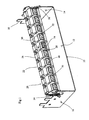
- this shows a metallic base unit 10 which comprises a floor portion 12 with upstanding parallel walls 14, 16 at either end thereof.
- Castellations such as shown at 18 extend upwardly from the upper edge of the walls 14, 16.
- the castellations 18 on the walls 14 and 16 are arranged so as to be in aligned pairs, one on each wall 14, 16. This permits a ten-connector array of terminals to be fitted onto each pair of castellations.
- a plurality of such arrays can be arranged in a generally parallel state to form a two dimensional array.
- FIG. 1 A single such array 20 of ten terminals 22 is shown in Figure 1. This array 20 is held in place by clips 24 which fit over the castellations 18.
- Each terminal 22 comprises a head portion 26 which is attached to a body portion 28 via a hinge line 30 at the rear of the terminal 22.
- the head portion 26 can move in a generally vertical direction.
- a pair of holes are formed on the front face of the head portion 26 and allow access to generally horizontal passageways, suitably sized to accept incoming wires.
- each connector 22 At the rear of each connector 22 is a socket 32 suitably sized to receive an arrestor 34.
- the socket 32 is integrally formed with the remainder of the plastics body of the terminal 22, and has an open rear face to allow insertion and removal of the arrestor 34.
- the open rear face also permits visual confirmation of the presence or absence of an arrestor.
- An earth bar 36 runs along the rear of the array 20 of connectors 22.
- a pair of spring contacts 38 at either end of the bar 36 provides grounding to the earthed base 10.
- a plurality of earth contacts 40 extend from the earth bar 36 and into the socket 32 via the open rear face. These earth contacts 40 are positioned so as to make contact with the earth connection 42 of the arrestor 34.
- FIG 2 shows the earthing bar 36 and arrestor 34 of Figure 1 more clearly.
- Figure 2 also shows the IDC connectors 44, 46 within the terminal 22. These each comprise a vertically disposed contact member with an IDC tip such as shown at 48 at either end thereof.
- the head portion 26 moves, as mentioned before, between a lower position in which the IDC tip 48 projects into the wire-receiving passage and arrays positioned in which the wire receiving passage is clear of the IDC tip 48.
- a wire pair can be inserted into the two openings at the front of the connector 22 with the head portion 26 in the raised position.
- the head portion 26 can then be depressed in a lower position in order to make electrical contact between the wires and the IDC connectors 44, 46.
- Figure 2 shows the contact arms 50, 52 extending from the two contact members 44, 46 alongside the respective inner walls of the body portion 28 (not shown in Figure 2). These project into the socket 32 and make contact with the contact caps 54,56 of the surge arrestor 34 via spring contacts such as shown at 58.
- Figure 3 shows the relevant parts of Figure 2 in more detail.
- the contact member 44 has a small lug 60 extending generally outwardly at roughly its waist portion.
- the contact arm 50 has a pair of downwardly depending lugs 62, 64 which define a gap therebetween into which the lug 60 is an interference fit. This provides an adequate electrical connection whilst allowing ease and reliability of manufacture.
- the positioning of the arrestor 34 permitted by this arrangement maintains it clear of both other connectors 32 and the usual access routes for wires to and from the terminals 22.
Landscapes
- Details Of Connecting Devices For Male And Female Coupling (AREA)
- Organic Insulating Materials (AREA)
- Reciprocating, Oscillating Or Vibrating Motors (AREA)
- Glass Compositions (AREA)
- Connections Arranged To Contact A Plurality Of Conductors (AREA)
- Contacts (AREA)
- Saccharide Compounds (AREA)
Priority Applications (1)
| Application Number | Priority Date | Filing Date | Title |
|---|---|---|---|
| EP03021644A EP1387439A3 (de) | 1997-03-19 | 1998-03-17 | Elektrischer Anschluss |
Applications Claiming Priority (2)
| Application Number | Priority Date | Filing Date | Title |
|---|---|---|---|
| GB9705714 | 1997-03-19 | ||
| GB9705714A GB2323482B (en) | 1997-03-19 | 1997-03-19 | Electrical terminal |
Related Child Applications (2)
| Application Number | Title | Priority Date | Filing Date |
|---|---|---|---|
| EP03021644A Division EP1387439A3 (de) | 1997-03-19 | 1998-03-17 | Elektrischer Anschluss |
| EP03021644.4 Division-Into | 2003-09-26 |
Publications (3)
| Publication Number | Publication Date |
|---|---|
| EP0866519A2 true EP0866519A2 (de) | 1998-09-23 |
| EP0866519A3 EP0866519A3 (de) | 1999-06-16 |
| EP0866519B1 EP0866519B1 (de) | 2004-05-12 |
Family
ID=10809527
Family Applications (2)
| Application Number | Title | Priority Date | Filing Date |
|---|---|---|---|
| EP03021644A Withdrawn EP1387439A3 (de) | 1997-03-19 | 1998-03-17 | Elektrischer Anschluss |
| EP98302000A Expired - Lifetime EP0866519B1 (de) | 1997-03-19 | 1998-03-17 | Elektrischer Kontakt |
Family Applications Before (1)
| Application Number | Title | Priority Date | Filing Date |
|---|---|---|---|
| EP03021644A Withdrawn EP1387439A3 (de) | 1997-03-19 | 1998-03-17 | Elektrischer Anschluss |
Country Status (7)
| Country | Link |
|---|---|
| US (1) | US6193556B1 (de) |
| EP (2) | EP1387439A3 (de) |
| AT (1) | ATE266901T1 (de) |
| DE (1) | DE69823726T2 (de) |
| ES (1) | ES2221123T3 (de) |
| GB (2) | GB2323482B (de) |
| PT (1) | PT866519E (de) |
Cited By (1)
| Publication number | Priority date | Publication date | Assignee | Title |
|---|---|---|---|---|
| WO2003046496A1 (de) | 2001-11-19 | 2003-06-05 | Epcos Ag | Messfühler und messfühleranordnung |
Families Citing this family (24)
| Publication number | Priority date | Publication date | Assignee | Title |
|---|---|---|---|---|
| DE10234111B4 (de) * | 2002-07-26 | 2013-11-28 | Automotive Lighting Reutlingen Gmbh | Elektrischer Kondensator |
| US7018230B2 (en) * | 2004-03-12 | 2006-03-28 | Channell Commercial Corporation | Electrical connector |
| US7303426B2 (en) * | 2004-03-12 | 2007-12-04 | Channell Commercial Corporation | Bridging connector |
| US7303425B2 (en) * | 2004-03-12 | 2007-12-04 | Channell Commercial Corporation | Electrical connector with filtering device |
| US7458840B2 (en) * | 2004-09-15 | 2008-12-02 | 3M Innovative Properties Company | Cap configured to removably connect to an insulation displacement connector block |
| US7335049B2 (en) * | 2004-09-15 | 2008-02-26 | 3M Innovative Properties Company | Connector assembly for housing insulation displacement elements |
| US7399197B2 (en) * | 2004-09-15 | 2008-07-15 | 3M Innovative Properties Company | Connector assembly for housing insulation displacement elements |
| US7101216B2 (en) * | 2004-09-15 | 2006-09-05 | 3M Innovative Properties Company | Insulation displacement system for two electrical conductors |
| US7373719B2 (en) | 2004-11-09 | 2008-05-20 | Channell Commercial Corporation | Method and process for manufacturing a terminal block |
| US7303446B2 (en) * | 2005-05-18 | 2007-12-04 | 3M Innovative Proprties Company | Frame assembly |
| US20060264090A1 (en) * | 2005-05-18 | 2006-11-23 | Dower William V | Electrical connector assembly and method of forming the same |
| US7331814B2 (en) * | 2005-06-30 | 2008-02-19 | 3M Innovative Properties Company | Apparatus configured to attach to an electrical connector block |
| US7223117B2 (en) * | 2005-06-30 | 2007-05-29 | 3M Innovative Properties Company | Circuit marker apparatus |
| US7165983B1 (en) | 2005-12-08 | 2007-01-23 | 3M Innovative Properties Company | Access cover configured to receive a testing device |
| US7413465B2 (en) * | 2006-04-12 | 2008-08-19 | Illinois Tool Works, Inc. | Insulation displacement system |
| US7347717B2 (en) * | 2006-04-12 | 2008-03-25 | Illinois Tool Works | Insulation displacement system |
| US7765695B2 (en) * | 2007-05-29 | 2010-08-03 | Channell Commercial Corporation | Method and process for manufacturing a terminal block |
| DE102007026097B4 (de) * | 2007-06-05 | 2023-05-11 | Tyco Electronics Services Gmbh | Steckverbinder für Leiterplatten |
| DE102007026094B4 (de) * | 2007-06-05 | 2023-05-11 | Tyco Electronics Services Gmbh | Kontaktelement für einen Steckverbinder für Leiterplatten |
| DE102007026096A1 (de) * | 2007-06-05 | 2008-12-11 | Adc Gmbh | Aderanschlussmodul |
| DE102007026102B3 (de) * | 2007-06-05 | 2008-11-13 | Adc Gmbh | Steckverbinder für Leiterplatten |
| DE102007026095A1 (de) * | 2007-06-05 | 2008-12-11 | Adc Gmbh | Erdkamm, insbesondere für einen Steckverbinder für Leiterplatten |
| DE102011016062B4 (de) * | 2011-04-05 | 2018-10-11 | Tyco Electronics Services Gmbh | Verteileranschlussmodul |
| DE102011016063A1 (de) * | 2011-04-05 | 2012-10-11 | Adc Gmbh | Verteileranschlussmodul |
Citations (2)
| Publication number | Priority date | Publication date | Assignee | Title |
|---|---|---|---|---|
| GB2293699A (en) * | 1994-09-29 | 1996-04-03 | Egerton A C Ltd | Reusable idc interconnector |
| EP0708497A2 (de) * | 1992-08-17 | 1996-04-24 | Minnesota Mining And Manufacturing Company | Verbessertes Durchgangs-Stecker-System für Telekommunikationssysteme |
Family Cites Families (15)
| Publication number | Priority date | Publication date | Assignee | Title |
|---|---|---|---|---|
| GB1500303A (en) * | 1975-10-08 | 1978-02-08 | Carr Fastener Co Ltd | Electrical connection assemblies |
| FR2337947A2 (fr) * | 1976-01-12 | 1977-08-05 | Reliable Electric Co | Bloc de raccordement notamment pour repartiteur telephonique |
| US4159500A (en) * | 1977-11-17 | 1979-06-26 | Reliable Electric Company | Modular line protector |
| US4272147A (en) * | 1979-09-14 | 1981-06-09 | Minnesota Mining And Manufacturing Company | Modular connector and protector |
| DE3021798C2 (de) * | 1980-06-11 | 1982-03-11 | Krone Gmbh, 1000 Berlin | Vorrichtung und Verfahren zur Herstellung eines Doppelkontaktes an einem löt-, schraub- und abisolierfreiem Klemmverbinder |
| DE3412468A1 (de) * | 1984-04-03 | 1985-10-10 | Siemens AG, 1000 Berlin und 8000 München | Verteilerleiste mit einer mehrzahl von den abisolierfreien anschluss elektrischer leiter gestattenden doppelanschlussklemmen |
| US4789354A (en) * | 1987-09-14 | 1988-12-06 | Minnesota Mining And Manufacturing Company | Voice/data communication termination connector |
| FR2671671A1 (fr) * | 1991-01-10 | 1992-07-17 | Mars Actel | Reglette de raccordement a protections semi-integrees. |
| JP3321164B2 (ja) * | 1991-10-11 | 2002-09-03 | レイケム・コーポレイション | 通信端子ブロック |
| FR2708794B1 (fr) * | 1993-08-04 | 1995-09-15 | Pouyet Int | Module d'interconnexion rapide de deux lignes téléphoniques monopaires. |
| US5399099A (en) * | 1993-08-12 | 1995-03-21 | The Whitaker Corporation | EMI protected tap connector |
| DE4331212C2 (de) * | 1993-09-10 | 1997-04-30 | Krone Ag | Klemmanschlußeinheit |
| US5451170A (en) * | 1993-09-28 | 1995-09-19 | Reliance Comm/Tec Corporation | Terminal block with protection |
| FR2717624B1 (fr) * | 1994-03-21 | 1996-04-26 | Cinch Connecteurs Sa | Organe de contact électrique femelle. |
| TW331046B (en) * | 1994-09-29 | 1998-05-01 | Whitaker Corp | Electrical connector for telecommunications |
-
1997
- 1997-03-19 GB GB9705714A patent/GB2323482B/en not_active Expired - Fee Related
- 1997-03-19 GB GB0118305A patent/GB2362273B/en not_active Expired - Fee Related
-
1998
- 1998-03-17 DE DE69823726T patent/DE69823726T2/de not_active Expired - Fee Related
- 1998-03-17 AT AT98302000T patent/ATE266901T1/de not_active IP Right Cessation
- 1998-03-17 EP EP03021644A patent/EP1387439A3/de not_active Withdrawn
- 1998-03-17 EP EP98302000A patent/EP0866519B1/de not_active Expired - Lifetime
- 1998-03-17 PT PT98302000T patent/PT866519E/pt unknown
- 1998-03-17 ES ES98302000T patent/ES2221123T3/es not_active Expired - Lifetime
- 1998-03-18 US US09/040,756 patent/US6193556B1/en not_active Expired - Fee Related
Patent Citations (2)
| Publication number | Priority date | Publication date | Assignee | Title |
|---|---|---|---|---|
| EP0708497A2 (de) * | 1992-08-17 | 1996-04-24 | Minnesota Mining And Manufacturing Company | Verbessertes Durchgangs-Stecker-System für Telekommunikationssysteme |
| GB2293699A (en) * | 1994-09-29 | 1996-04-03 | Egerton A C Ltd | Reusable idc interconnector |
Cited By (2)
| Publication number | Priority date | Publication date | Assignee | Title |
|---|---|---|---|---|
| WO2003046496A1 (de) | 2001-11-19 | 2003-06-05 | Epcos Ag | Messfühler und messfühleranordnung |
| US7311014B2 (en) | 2001-11-19 | 2007-12-25 | Epcos Ag | Sensor and sensor assembly |
Also Published As
| Publication number | Publication date |
|---|---|
| DE69823726T2 (de) | 2005-05-04 |
| GB2323482A (en) | 1998-09-23 |
| ES2221123T3 (es) | 2004-12-16 |
| DE69823726D1 (de) | 2004-06-17 |
| US6193556B1 (en) | 2001-02-27 |
| GB2323482B (en) | 2001-11-14 |
| GB2362273B (en) | 2002-01-16 |
| GB0118305D0 (en) | 2001-09-19 |
| PT866519E (pt) | 2004-09-30 |
| GB9705714D0 (en) | 1997-05-07 |
| GB2362273A (en) | 2001-11-14 |
| EP0866519A3 (de) | 1999-06-16 |
| EP1387439A2 (de) | 2004-02-04 |
| EP1387439A3 (de) | 2008-03-26 |
| EP0866519B1 (de) | 2004-05-12 |
| ATE266901T1 (de) | 2004-05-15 |
Similar Documents
| Publication | Publication Date | Title |
|---|---|---|
| EP0866519B1 (de) | Elektrischer Kontakt | |
| CA2017173C (en) | Connector bank with overvoltage surge protection | |
| US5627721A (en) | Protector cartridge for modular connector blocks | |
| US4851967A (en) | Distribution bank for communication cables | |
| KR100208649B1 (ko) | 통신 커넥터 | |
| US5647760A (en) | Insulation displacement contact including retention means | |
| CA2008719C (en) | Connector bank | |
| US7946863B2 (en) | Circuit protection block | |
| US7037118B2 (en) | Access module | |
| JPH01313863A (ja) | 接続又は分離列用の保護プラグ | |
| EP0852412A3 (de) | Verbinder für Flachkabel | |
| US7534149B2 (en) | Plugless normally-open connector module | |
| CA2175955A1 (en) | Insulation displacement terminal with two-wire insertion capability | |
| US6093041A (en) | Connector block with internal power bus | |
| CN112703644B (zh) | 用于被屏蔽的连接器的插座 | |
| JPH09190849A (ja) | 通信導線やデータ導線の主分配部のケーブル接続用のモジュール式多重接続端子ブロック | |
| JPH0389474A (ja) | 電気通信設備用接続台 | |
| JPS5936845Y2 (ja) | コンタクト | |
| US4904210A (en) | Telecommunications connector | |
| CA1284832C (en) | Telecommunications connector | |
| IL115702A0 (en) | Modular telecommunications terminal block | |
| JPS631287A (ja) | 主配線盤用端子板及び主配線盤 |
Legal Events
| Date | Code | Title | Description |
|---|---|---|---|
| PUAI | Public reference made under article 153(3) epc to a published international application that has entered the european phase |
Free format text: ORIGINAL CODE: 0009012 |
|
| AK | Designated contracting states |
Kind code of ref document: A2 Designated state(s): AT CH DE ES FR GB GR IE IT LI PT |
|
| AX | Request for extension of the european patent |
Free format text: AL;LT;LV;MK;RO;SI |
|
| PUAL | Search report despatched |
Free format text: ORIGINAL CODE: 0009013 |
|
| AK | Designated contracting states |
Kind code of ref document: A3 Designated state(s): AT BE CH DE DK ES FI FR GB GR IE IT LI LU MC NL PT SE |
|
| AX | Request for extension of the european patent |
Free format text: AL;LT;LV;MK;RO;SI |
|
| RIC1 | Information provided on ipc code assigned before grant |
Free format text: 6H 01R 4/24 A, 6H 01R 9/24 B, 6H 04Q 1/14 B |
|
| 17P | Request for examination filed |
Effective date: 19991201 |
|
| AKX | Designation fees paid |
Free format text: AT CH DE ES FR GB GR IE IT LI PT |
|
| 17Q | First examination report despatched |
Effective date: 20001212 |
|
| GRAG | Despatch of communication of intention to grant |
Free format text: ORIGINAL CODE: EPIDOS AGRA |
|
| GRAG | Despatch of communication of intention to grant |
Free format text: ORIGINAL CODE: EPIDOS AGRA |
|
| GRAS | Grant fee paid |
Free format text: ORIGINAL CODE: EPIDOSNIGR3 |
|
| GRAP | Despatch of communication of intention to grant a patent |
Free format text: ORIGINAL CODE: EPIDOSNIGR1 |
|
| GRAU | Approval following communication of intention to grant |
Free format text: ORIGINAL CODE: EPIDOSNAGR4 |
|
| RAP1 | Party data changed (applicant data changed or rights of an application transferred) |
Owner name: CHANNELL LIMITED |
|
| GRAA | (expected) grant |
Free format text: ORIGINAL CODE: 0009210 |
|
| AK | Designated contracting states |
Kind code of ref document: B1 Designated state(s): AT CH DE ES FR GB GR IE IT LI PT |
|
| REG | Reference to a national code |
Ref country code: GB Ref legal event code: FG4D |
|
| REG | Reference to a national code |
Ref country code: CH Ref legal event code: EP |
|
| REG | Reference to a national code |
Ref country code: IE Ref legal event code: FG4D |
|
| REF | Corresponds to: |
Ref document number: 69823726 Country of ref document: DE Date of ref document: 20040617 Kind code of ref document: P |
|
| REG | Reference to a national code |
Ref country code: CH Ref legal event code: NV Representative=s name: BRAUN & PARTNER PATENT-, MARKEN-, RECHTSANWAELTE |
|
| REG | Reference to a national code |
Ref country code: PT Ref legal event code: SC4A Free format text: AVAILABILITY OF NATIONAL TRANSLATION Effective date: 20040805 |
|
| REG | Reference to a national code |
Ref country code: GR Ref legal event code: EP Ref document number: 20040402729 Country of ref document: GR |
|
| REG | Reference to a national code |
Ref country code: ES Ref legal event code: FG2A Ref document number: 2221123 Country of ref document: ES Kind code of ref document: T3 |
|
| ET | Fr: translation filed | ||
| PGFP | Annual fee paid to national office [announced via postgrant information from national office to epo] |
Ref country code: IE Payment date: 20050310 Year of fee payment: 8 |
|
| PGFP | Annual fee paid to national office [announced via postgrant information from national office to epo] |
Ref country code: PT Payment date: 20050314 Year of fee payment: 8 |
|
| PGFP | Annual fee paid to national office [announced via postgrant information from national office to epo] |
Ref country code: GR Payment date: 20050315 Year of fee payment: 8 |
|
| PGFP | Annual fee paid to national office [announced via postgrant information from national office to epo] |
Ref country code: GB Payment date: 20050316 Year of fee payment: 8 |
|
| PLBE | No opposition filed within time limit |
Free format text: ORIGINAL CODE: 0009261 |
|
| STAA | Information on the status of an ep patent application or granted ep patent |
Free format text: STATUS: NO OPPOSITION FILED WITHIN TIME LIMIT |
|
| PGFP | Annual fee paid to national office [announced via postgrant information from national office to epo] |
Ref country code: FR Payment date: 20050330 Year of fee payment: 8 Ref country code: CH Payment date: 20050330 Year of fee payment: 8 |
|
| PGFP | Annual fee paid to national office [announced via postgrant information from national office to epo] |
Ref country code: AT Payment date: 20050331 Year of fee payment: 8 |
|
| PGFP | Annual fee paid to national office [announced via postgrant information from national office to epo] |
Ref country code: ES Payment date: 20050428 Year of fee payment: 8 |
|
| 26N | No opposition filed |
Effective date: 20050215 |
|
| PGFP | Annual fee paid to national office [announced via postgrant information from national office to epo] |
Ref country code: DE Payment date: 20050531 Year of fee payment: 8 |
|
| PG25 | Lapsed in a contracting state [announced via postgrant information from national office to epo] |
Ref country code: IE Free format text: LAPSE BECAUSE OF NON-PAYMENT OF DUE FEES Effective date: 20060317 Ref country code: GB Free format text: LAPSE BECAUSE OF NON-PAYMENT OF DUE FEES Effective date: 20060317 Ref country code: AT Free format text: LAPSE BECAUSE OF NON-PAYMENT OF DUE FEES Effective date: 20060317 |
|
| PG25 | Lapsed in a contracting state [announced via postgrant information from national office to epo] |
Ref country code: ES Free format text: LAPSE BECAUSE OF NON-PAYMENT OF DUE FEES Effective date: 20060318 |
|
| PG25 | Lapsed in a contracting state [announced via postgrant information from national office to epo] |
Ref country code: LI Free format text: LAPSE BECAUSE OF NON-PAYMENT OF DUE FEES Effective date: 20060331 Ref country code: CH Free format text: LAPSE BECAUSE OF NON-PAYMENT OF DUE FEES Effective date: 20060331 |
|
| PGFP | Annual fee paid to national office [announced via postgrant information from national office to epo] |
Ref country code: IT Payment date: 20060331 Year of fee payment: 9 |
|
| PG25 | Lapsed in a contracting state [announced via postgrant information from national office to epo] |
Ref country code: PT Free format text: LAPSE BECAUSE OF NON-PAYMENT OF DUE FEES Effective date: 20060918 |
|
| PG25 | Lapsed in a contracting state [announced via postgrant information from national office to epo] |
Ref country code: DE Free format text: LAPSE BECAUSE OF NON-PAYMENT OF DUE FEES Effective date: 20061003 |
|
| REG | Reference to a national code |
Ref country code: CH Ref legal event code: PL |
|
| GBPC | Gb: european patent ceased through non-payment of renewal fee |
Effective date: 20060317 |
|
| REG | Reference to a national code |
Ref country code: PT Ref legal event code: MM4A Free format text: LAPSE DUE TO NON-PAYMENT OF FEES Effective date: 20060918 |
|
| REG | Reference to a national code |
Ref country code: IE Ref legal event code: MM4A |
|
| REG | Reference to a national code |
Ref country code: FR Ref legal event code: ST Effective date: 20061130 |
|
| REG | Reference to a national code |
Ref country code: ES Ref legal event code: FD2A Effective date: 20060318 |
|
| PG25 | Lapsed in a contracting state [announced via postgrant information from national office to epo] |
Ref country code: FR Free format text: LAPSE BECAUSE OF NON-PAYMENT OF DUE FEES Effective date: 20060331 |
|
| PG25 | Lapsed in a contracting state [announced via postgrant information from national office to epo] |
Ref country code: GR Free format text: LAPSE BECAUSE OF NON-PAYMENT OF DUE FEES Effective date: 20061002 |
|
| PG25 | Lapsed in a contracting state [announced via postgrant information from national office to epo] |
Ref country code: IT Free format text: LAPSE BECAUSE OF NON-PAYMENT OF DUE FEES Effective date: 20070317 |