EP0865327B1 - Dispositif de reglage pour vibrateur a balourd avec couple centrifuge reglable - Google Patents
Dispositif de reglage pour vibrateur a balourd avec couple centrifuge reglable Download PDFInfo
- Publication number
- EP0865327B1 EP0865327B1 EP96939923A EP96939923A EP0865327B1 EP 0865327 B1 EP0865327 B1 EP 0865327B1 EP 96939923 A EP96939923 A EP 96939923A EP 96939923 A EP96939923 A EP 96939923A EP 0865327 B1 EP0865327 B1 EP 0865327B1
- Authority
- EP
- European Patent Office
- Prior art keywords
- motors
- unbalanced mass
- hydraulic
- relative
- position angle
- Prior art date
- Legal status (The legal status is an assumption and is not a legal conclusion. Google has not performed a legal analysis and makes no representation as to the accuracy of the status listed.)
- Expired - Lifetime
Links
- 238000006243 chemical reaction Methods 0.000 claims description 28
- 230000001105 regulatory effect Effects 0.000 claims description 14
- 239000013598 vector Substances 0.000 claims description 14
- 230000009471 action Effects 0.000 claims description 8
- 230000003068 static effect Effects 0.000 claims description 7
- 230000001133 acceleration Effects 0.000 claims description 5
- 230000008878 coupling Effects 0.000 claims description 3
- 238000010168 coupling process Methods 0.000 claims description 3
- 238000005859 coupling reaction Methods 0.000 claims description 3
- 238000010348 incorporation Methods 0.000 claims 1
- 230000000694 effects Effects 0.000 description 18
- 238000010586 diagram Methods 0.000 description 14
- 230000001360 synchronised effect Effects 0.000 description 13
- 230000008859 change Effects 0.000 description 6
- 230000001172 regenerating effect Effects 0.000 description 6
- 238000000034 method Methods 0.000 description 5
- 238000011161 development Methods 0.000 description 4
- 230000018109 developmental process Effects 0.000 description 4
- 230000006872 improvement Effects 0.000 description 4
- 230000008901 benefit Effects 0.000 description 3
- 230000033228 biological regulation Effects 0.000 description 3
- 230000005540 biological transmission Effects 0.000 description 2
- 238000005516 engineering process Methods 0.000 description 2
- 230000002349 favourable effect Effects 0.000 description 2
- 239000012530 fluid Substances 0.000 description 2
- 230000008569 process Effects 0.000 description 2
- 230000009467 reduction Effects 0.000 description 2
- 230000001419 dependent effect Effects 0.000 description 1
- 230000005284 excitation Effects 0.000 description 1
- 230000005484 gravity Effects 0.000 description 1
- 239000010720 hydraulic oil Substances 0.000 description 1
- 230000010354 integration Effects 0.000 description 1
- 238000002372 labelling Methods 0.000 description 1
- 238000012423 maintenance Methods 0.000 description 1
- 238000012986 modification Methods 0.000 description 1
- 230000004048 modification Effects 0.000 description 1
- 230000010355 oscillation Effects 0.000 description 1
- 230000035515 penetration Effects 0.000 description 1
- 238000004321 preservation Methods 0.000 description 1
- 230000002441 reversible effect Effects 0.000 description 1
- 239000002689 soil Substances 0.000 description 1
Images

Classifications
-
- B—PERFORMING OPERATIONS; TRANSPORTING
- B06—GENERATING OR TRANSMITTING MECHANICAL VIBRATIONS IN GENERAL
- B06B—METHODS OR APPARATUS FOR GENERATING OR TRANSMITTING MECHANICAL VIBRATIONS OF INFRASONIC, SONIC, OR ULTRASONIC FREQUENCY, e.g. FOR PERFORMING MECHANICAL WORK IN GENERAL
- B06B1/00—Methods or apparatus for generating mechanical vibrations of infrasonic, sonic, or ultrasonic frequency
- B06B1/10—Methods or apparatus for generating mechanical vibrations of infrasonic, sonic, or ultrasonic frequency making use of mechanical energy
- B06B1/16—Methods or apparatus for generating mechanical vibrations of infrasonic, sonic, or ultrasonic frequency making use of mechanical energy operating with systems involving rotary unbalanced masses
- B06B1/161—Adjustable systems, i.e. where amplitude or direction of frequency of vibration can be varied
- B06B1/166—Where the phase-angle of masses mounted on counter-rotating shafts can be varied, e.g. variation of the vibration phase
-
- B—PERFORMING OPERATIONS; TRANSPORTING
- B06—GENERATING OR TRANSMITTING MECHANICAL VIBRATIONS IN GENERAL
- B06B—METHODS OR APPARATUS FOR GENERATING OR TRANSMITTING MECHANICAL VIBRATIONS OF INFRASONIC, SONIC, OR ULTRASONIC FREQUENCY, e.g. FOR PERFORMING MECHANICAL WORK IN GENERAL
- B06B1/00—Methods or apparatus for generating mechanical vibrations of infrasonic, sonic, or ultrasonic frequency
- B06B1/18—Methods or apparatus for generating mechanical vibrations of infrasonic, sonic, or ultrasonic frequency wherein the vibrator is actuated by pressure fluid
- B06B1/186—Methods or apparatus for generating mechanical vibrations of infrasonic, sonic, or ultrasonic frequency wherein the vibrator is actuated by pressure fluid operating with rotary unbalanced masses
Definitions
- the invention relates to an adjusting device for adjusting the relative setting angle ⁇ of Imbalance vibrators with at least two pairs of partially unbalanced bodies that can be adjusted against each other.
- a special type of adjustment device is in the patent DE 40 00 011 or in the PCT / EP90 / 02239.
- For the subsequent description of the present invention simplifying the terms used in the last-mentioned publication of the partial unbalance body and the assigned to them partial centrifugal forces (or partial centrifugal force vectors), and the "pair" of partial unbalance bodies accepted.
- the relative setting angle ⁇ is theoretically defined between the partial centrifugal force vectors of the individual partial unbalance bodies of a "pair" of partial unbalance bodies. In practice you can use the relative setting angle ⁇ also define the partial unbalance body between features (e.g. geometric features) Pair, if the position of the center of gravity of the eccentric mass is known.
- the invention is particularly dedicated to the unbalance vibrators with a predetermined direction of vibration, which e.g. are used as ramming vibrators and in which at least four unbalanced shafts or partial unbalance bodies are present, which are rotatable in corresponding bearings of the vibrator frame are arranged.
- These vibrators there is every unbalanced shaft or each unbalanced body a separate motor assigned without the interposition of a transmission.
- The serves Motor at the same time as a drive motor for the implementation of the useful power or friction power (screed friction and bearing friction with the ramming vibrator) and as an adjustment motor.
- Through this type of energy supply for the Partial unbalance bodies can be dispensed with otherwise customary gear transmissions.
- these vibrators are said to be hereinafter referred to as "gearless vibrators with adjustable unbalance moment".
- the motors that are used with the invention can be hydraulic motors, which normally can work both as motors and pumps, act or also around electric motors.
- the hydraulic motors are driven by the volume flow of one Fluid medium (e.g. hydraulic oil), whereby the volume flow must be generated by one or more Pumps that are driven by one or more engines (e.g. diesel engine).
- Figure 1 is a hydraulic operated "gearless vibrator" with adjustable unbalance moment shown with the first Partial unbalance bodies associated with first motors 103 and 104 and the second partial unbalance bodies associated second motors 107 and 108.
- the first two motors are parallel and supplied with the same inlet pressure by one generated by the adjustable pump 114 Volume flow.
- the two second motors are each connected to a first motor by means of a Series connection connected. It is a so-called open circuit of the fluid medium.
- the adjustment range for the adjustment of the unbalance torque is limited to an angle 0 ° ⁇ ⁇ ⁇ 90 °.
- the vibrator shown is provided with the ability to mirror the synchronous movement To be able to maintain the angle of rotation of the partial unbalance bodies of the same type, even under the influence of disturbing forces to be expected in general, but at least in the adjustment range at which the maximum unbalance torque is adjustable. This ability is seen as derived from the Effects of those alternating moments which are generated by the reaction moments MR and which is also responsible for the development of the average reaction moments MRQ are.
- the vibrator shown has a additional disadvantage to consider that in order to achieve comparably large resulting unbalance moments the partial unbalance moments of the partial unbalance bodies are dimensioned larger than normal have to. This leads to unnecessarily increased bearing forces and reaction torques MRQ.
- Patent DE 40 00 011 What is remarkable is a closer examination of the circuit shown resulting fact that the throttling shown in Figure 1 of the flow through motor 116 Volume flow with the help of the pressure relief valve 124 can not lead (starting from a Position in which the resulting unbalance moment has the value zero) the relative positioning angle ⁇ to change in such a way that the resulting unbalance moment increases. To really get this effect it would be necessary to be able to use the function of element 124 to that a pressure increase takes place between the input and output of the engine 116 while at the same time Motor 114 between inlet and outlet a decrease in pressure takes place.
- Patent DE 41 16 647 Here an adjustable gearless vibrator with electric motors is shown, each motor is assigned its own electronic control device. It exists for every engine a measuring device by means of which the relative angular position of all partial unbalance bodies relative to one another can be measured continuously.
- the angle of rotation of a first partial unbalance body is as The reference position is defined and the angles of rotation of the remaining three partial unbalance bodies are called relative Angle measured with respect to the first partial unbalance body.
- the individual Regulation of the angle of rotation of each partial unbalance body achieves that in addition to the adjustment of the Given the relative positioning angle ⁇ , the mirror-image symmetrical angle of rotation position at the same time is maintained between the partial unbalance bodies of the same type.
- This solution is not only not suitable for use with ramming vibrators due to the enormous effort involved.
- the one shown The solution is a good example of the variety with which the 4 motors can be loaded adjustable gearless vibrator can be done.
- DE-OS 44 25 905 provides a contribution to a state of the art as it was later published:
- a solution is described with the help of which, in particular in the case of gearless vibrators which one can adjust the resulting unbalance moment with additional measures Can force synchronous running from that relative angle of rotation which is definable between the partial unbalance bodies of the same kind.
- This contribution does not give any indication of the solution of the existing Task with the present invention, but he points to the problem of compliance with the Synchronous running of the relative rotation angle between the partial unbalance bodies of the same type.
- the state described by DE-OS 43 01 368 Improve technology for use with gearless vibrators using hydraulic motors or are driven by electric motors and the resulting unbalance moment are adjustable.
- the goal of the improvement is to achieve 4 goals: at least if it has been achieved Setting the resulting resulting unbalance moment and maximum adjustable for the solution found with the delivery of high useful output (in the case of ram vibrators via the ram plank in the Soil) should at least at a set maximum unbalance moment (which in practice the most of the work is) a load of all four motors of the same size can be achieved.
- hydraulic motors in compliance with this condition use the pumps to be used in both open and closed circuits.
- the use of closed circuits can bring advantages, for example, through the possible ones Type of circuit. For example, when using open circuits it may be advantageous to to be able to select a larger number of pump types.
- the task is as follows:
- the necessary relative angle of rotation must be securely held, at least for that adjustment range of the relative -Position angle ⁇ , in which a maximum can be set for the resulting unbalance moment, because a significant working range of the vibrator is seen in this adjustment range.
- cross vibrations which are not permitted are generated.
- the mechanical reactive power which has to be introduced into the motor-driven motors and which is passed on to the shafts of the partial unbalance bodies of the one type (as a power corresponding to the product from reaction moment MRQ times angular frequency ⁇ ), is transformed in a first conversion step into the "power of the kinetic energy" of the vibrating mass (this mass is also called “dynamic mass” m dyn ).
- the "power of the kinetic energy” is transformed again into a mechanical reactive power, which has to be released again by the waves of the partial unbalance bodies of the other type (as a power from the reaction moment MRQ times ⁇ ).
- This power is emitted by the waves with a first part as the friction power of the bearings and with a second part as the power which is converted from the generator-operated motors into a generator power and which must be delivered by these motors.
- the nature of the effect of these funds can, by the way, only be explained on the basis of the diagrams in FIG.
- the solution according to the invention uses, for the sake of simplicity, a principle at which it is not necessary to measure the angle of rotation ⁇ of a single partial unbalance body, but only the relative setting angle ⁇ , and at which the two motors of a group together and in parallel switched to be supplied with drive power.
- this requires that the mirror image symmetrical synchronous relative rotation angle ⁇ between partial unbalance bodies of the same type (a group) is maintained through the use of other means.
- Figure 1 shows in schematic form and in the manner of a hydraulic plan for the hydraulic Solution variant the configuration of pumps and motors of a gearless vibrator according to the invention.
- FIG. 1 shows (with a symbolic representation of the 4 partial unbalance bodies by 4 corresponding circles) two partial unbalance bodies of one type 102, 104 and two partial unbalance bodies of the other type 106, 108, which can rotate (in a manner not shown) about their axes, which are supported in bearings in the vibrator frame.
- Each partial unbalance body is connected to its own hydraulic motor, by means of which it can be driven or braked for the purpose of adjusting the relative setting angle ⁇ and through which the partial unbalance body is supplied with the power which is subsequently lost in the form of bearing friction power, and which flows in part in the form of useful power, for example given to the pile driver, into the ground after this part of the power has previously been transferred to the oscillating dynamic mass m dyn by means of the bearing forces.
- the partial unbalance bodies of one type 102, 104 are the motors 110, 112 assigned to one type and the partial unbalance bodies of the other type 106, 108 are the motors 114, 1 16 assigned to the other type.
- the respective direction of rotation of the motors and the partial unbalance body is shown by arrows with the sign ⁇ .
- the motors of the same type are in parallel connected to a closed hydraulic circuit of one type 118 or the other type 120, whose volume flow is generated by a respective assigned pump P1 of the one type or pump P2 of a different kind.
- the motors and the pump P2 of the Hydraulic circuit of a different kind generate pressure differences in both directions. That means that the Motors can work both as motors (motor) and as pumps (generator) and that Pump P2 can work both as a pump (generator) and as a motor (motor).
- Both pumps are connected to a common diesel engine via a DM Drive device 122.
- the drive device could be a common shaft or a Distributor gearboxes.
- Both pumps are symbolized by arrows 126 and 128, equipped with adjusting devices for adjusting the delivery volume, so that with the help of these pump adjustment devices in their synchronous change the Volume flows and thus the rotational frequencies of the motors within specified limits can be changed.
- a component 130 is installed, which is flowed through by the volume flow of the return line 120 and which is capable of Throttle volume flow in a predetermined manner and thereby a predetermined pressure in the supply line in front of its entrance.
- the amount of pressure built up in this way can be specified by means of an electrical control device, which the Component 130 influences via an electrical line 132.
- reaction moments act on the partial unbalance bodies of the other type 106, 108 MRQ in the direction of rotation.
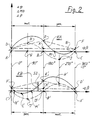
- FIG. 2 Two diagrams are shown in FIG. 2, of which the upper diagram with the characteristic curve KA describes certain states on motors 110, 112 of one type and the lower one Diagram with the characteristic curve KB certain states on the motors 114, 116 of the others Art describes.
- the relative setting angle ⁇ is on the abscissa axis plotted, while the values of the ordinate axis are interpreted as different variables that can be derived from each other as different variables are provided: the differential pressure ⁇ p at the motors, the differential torque ⁇ MD (proportional to ⁇ p) on the motors and the differential power ⁇ P (proportional to ⁇ p) of the motors.
- the characteristic curves KA and KB result from the superposition or addition of different variables, what in the example the diagram variable "differential torque ⁇ MD" is explained in more detail.
- the characteristic curves KA and In this case, KB represent the torques that act on the motors.
- the broken line D-E-F shows the torque curve which the entire friction power is generated.
- the entire friction work comprises two components: The a component is indicated by the broken line D-K-F, which is the friction torque of the Bearing friction represented with a size corresponding to the distance A-D.
- the bearing friction has over the whole angular range a constant size.
- the linear curve of the useful torque is a simplification of the non-linear course of useful torque in practice. The The simplification shown is based on the assumption that the useful torque is roughly proportional to the size of the vibration amplitude, which is also known to be related to the size of the angle ⁇ changed.
- the magnitude of the reaction torque MRQ which is dependent on the angle ⁇ , runs according to FIG broken line A-H-B-J-C.
- the characteristic curve KA is drawn for the operation of a ramming vibrator with high Load from the useful work, which is transferred from the pile to the earth. With a small proportion of useful work, point E moves downwards in the direction of point K. When the ramming vibrator is idling (without touching between Pile and earth) and the useful work is zero, point E coincides with that Point K together. It is also mentioned that the size of the maximum value of the Reaction torque MRQ (distance G-H) varies both with the size of the dynamic Mass, which also includes the mass of the pile, as well as the depth of the Penetration of the pile into the ground, or with the size of the submitted work.
- the angle ⁇ 180 ° the torques ⁇ MD, which load the motors of one and the other type, of the same size and positive in both cases, which means a purely motor load of the motors is given.
- the relative setting angle ⁇ must on the motors of one type the differential torques according to the characteristic curve KA and at the same time, the differential torques on the motors of the other type according to the characteristic KB must be set.
- independent claims 1 and 2 are based on the exemplary embodiment according to Figure 1, which in principle is a (particularly important) further development of the Description of Figure 2 disclosed main idea of the invention.
- Independent claims 3 and 4 describe the technical teaching from the main idea set out in Figure 2 when used in Connection with hydraulic or electric motors. Claims 3 and 4 do not require any special explanatory description. For the practical execution of one with electric motors operated vibrator, you can also use the arrangement according to FIG. 1 if you are in FIG. 1 presents the following modifications as given:
- Motors 110, 112 and 114, 116 are electric motors and lines 144, 146 and 140, 142 represent the electrical leads to the motors. Component 130 is omitted.
- the symbols for the Pumps P1 and P2 each represent an electrical control device with which the motors can be varied Speeds and forced to develop variable torques in different directions can be. At least on the motors 114, 116, a negative torque can also be generated be developed while using a positive torque on the motors 110, 112 at the same time reached.
Landscapes
- Engineering & Computer Science (AREA)
- Mechanical Engineering (AREA)
- Apparatuses For Generation Of Mechanical Vibrations (AREA)
Claims (16)
- Dispositif de réglage pour un vibrateur à balourds possédant les particularités suivantes :caractérisé par la combinaison des caractéristiques suivantes :il est prévu au moins deux paires de corps de balourd partiels (102, 106 ; 104, 108) qui peuvent être entraínées en rotation autour d'un axe correspondant et dont les vecteurs de forces centrifuges partielles, ajoutés en somme vectorielle, forment le vecteur force centrifuge résultant sous l'effet duquel la masse du vibrateur décrit des vibrations orientées.à chaque corps de balourd partiel, est associé un moment de balourd partiel qui peut être considéré comme un vecteur, et tous les moments de balourds partiels forment, par leur somme vectorielle, le moment de balourd résultant qui est proportionnel au vecteur de force centrifuge résultant,chaque paire est formée d'un corps de balourd partiel partiel d'un premier genre (102 ; 104) et d'un corps de balourd partiel d'un second genre (106 ; 108), et entre les vecteurs de forces centrifuges des corps de balourd partiels d'une paire, peut être défini, pour une position de rotation entièrement déterminée des deux corps de balourd partiels, un angle de calage relatif β,chaque corps de balourd partiel du premier genre et du second genre est muni de son propre moteur du premier genre (110, 112) ou, respectivement, du second genre (114, 116), et le rotor de chaque moteur est relié à son corps de balourd partiel de telle manière qu'un moment de rotation puisse être transmis du rotor au corps de balourd partiel (et inversement),il est prévu au moins un dispositif de commande ou un dispositif de régulation pour l'établissement direct ou indirect d'une valeur pouvant être prédéterminée pour l'angle de calage relatif β ou d'une valeur pouvant être prédéterminée pour l'amplitude de la course d'oscillation x ou d'une dérivée x' ou x" de cette course par rapport au temps, l'une des limites de la plage des valeurs pouvant être prédéterminée en correspondance avec un vecteur de force centrifuge résultant minimum et l'autre limite de la plage des valeurs pouvant être prédéterminée en correspondance avec un vecteur de force centrifuge résultant maximum,a) les moteurs à fonctionnement hydraulique du premier genre (110, 112) sont raccordés en parallèle à un circuit hydraulique propre du premier genre, les moteurs à fonctionnement hydraulique du second genre (114, 116) sont raccordés en parallèle à un circuit hydraulique propre d'un second genre, et chaque circuit hydraulique du premier genre et du second genre comprend au moins une pompe propre du premier genre (P1) ou, respectivement, du second genre (P2),b) le point de fonctionnement, pouvant être défini par la grandeur établie de l'angle de calage relatif β pour le moment de balourd résultant maximum réglable, peut être choisi aussi à un angle de calage relatif β supérieur à β = ± 90° comme, par exemple, à un angle de calage relatif dans le voisinage de β = ± 180° ou exactement de cette valeur,c) il est prévu un dispositif de mesure pour la mesure de la valeur réelle variable de réglage (par exemple amplitude, vitesse ou accélération du mouvement oscillant, ou angle β lui-même) pour laquelle la valeur de l'angle de calage relatif β est influencée directement ou indirectement, la valeur réelle de la variable de réglage étant destinée à être traitée par le dispositif de commande ou le dispositif de régulation,d) la plage de réglage de l'angle de calage relatif β, depuis environ β = 0° jusqu'à environ β = ± 180° peut être parcourue, du moins dans le fonctionnement du vibrateur sans application d'une puissance utile, par un fonctionnement purement dans le mode moteur des moteurs du premier genre (110, 112) et par un fonctionnement alternativement dans le mode générateur et dans le mode moteur des moteurs du second genre (114, 116),e) la puissance hydraulique engendrée pendant le fonctionnement dans le mode générateur des moteurs du second genre (114, 116) au moyen de l'élévation de la pression dans le courant volumique circulant entre l'entrée et la sortie des moteurs du second genre (114, 116) est sensiblement transformée, entre l'entrée et la sortie de la pompe (P2) du second genre, avec diminution simultanée de la pression dans le courant volumique, en une puissance correspondante dans le mode moteur, puissance qui est appliquée par la pompe (P2),f) chaque pompe (P1, P2) est munie d'un raccordement (122) menant à au moins un moteur d'entraínement (MD), par lequel raccordement une puissance d'entraínement peut être fournie à la pompe (P1, P2) ou être prélevée sur cette pompe.
- Dispositif de réglage selon le préambule de la revendication 1, caractérisé par la combinaison des caractéristiques suivantes :a) les moteurs à fonctionnement hydraulique du premier genre (110, 112) sont raccordés en parallèle à un circuit hydraulique propre du premier genre, les moteurs à fonctionnement hydraulique du second genre (114, 116) sont raccordés en parallèle à un circuit hydraulique propre d'un second genre, et chaque circuit hydraulique du premier genre et du second genre comprend au moins une pompe propre du premier genre (P1) ou, respectivement, du second genre (P2),b) le point de fonctionnement, pouvant être défini par la grandeur établie de l'angle de calage relatif β pour le moment de balourd résultant maximum réglable, peut être choisi aussi à un angle de calage relatif β supérieur à β = ± 90° comme, par exemple, à un angle de calage relatif dans le voisinage de β = ± 180° ou exactement de cette valeur,c) il est prévu un dispositif de mesure pour la mesure de la valeur réelle variable de réglage (par exemple amplitude, vitesse ou accélération du mouvement oscillant, ou angle β lui-même) pour laquelle la valeur de l'angle de calage relatif β est influencée directement ou indirectement, la valeur réelle de la variable de réglage étant destinée à être traitée par le dispositif de commande ou le dispositif de régulation,d) la plage de réglage de l'angle de calage relatif β, depuis environ β = 0° jusqu'à environ β = ± 180° peut être parcourue, du moins dans le fonctionnement du vibrateur sans développement d'une puissance utile, par un fonctionnement purement dans le mode moteur des moteurs du premier genre (110, 112) et par un fonctionnement alternativement dans le mode générateur et dans le mode moteur des moteurs du second genre (114, 116),e) la puissance hydraulique engendrée pendant le fonctionnement dans le mode générateur des moteurs du second genre (114, 116) au moyen de l'élévation de la pression dans le courant volumique circulant entre l'entrée et la sortie des moteurs de second genre (114, 116) est sensiblement transformée, par l'action d'un organe (130) de transformation de puissance, avec diminution simultanée de la pression dans le courant volumique entre l'entrée et la sortie de l'organe (130) de transformation de la puissance, en une autre sorte de puissance, laquelle puissance n'est pas renvoyée, ou du moins pas directement, à la pompe du premier genre (P1), la puissance hydraulique pouvant être transformée par l'organe (130) de transformation de la puissance, en la puissance d'une autre forme de phénomène physique (par exemple transformation en une puissance thermique lorsque l'organe de transformation de la puissance est réalisé sous la forme d'un étranglement).f) chaque pompe (P1, P2) est munie d'un raccordement (122) menant à au moins un moteur d'entraínement (MD), par lequel raccordement une puissance d'entraínement peut être fournie à la pompe (P1, P2) ou être prélevée sur cette pompe.
- Dispositif de réglage pour un vibrateur à balourds possédant les caractéristiques suivantes :caractérisé par la combinaison des caractéristiques suivantes :il est prévu au moins deux groupes de corps de balourd partiels (102, 104 ; 106, 108) qui peuvent être entraínés pour tourner autour d'un axe correspondant, la masse du vibrateur à balourd étant contrainte à exécuter des oscillations orientées par l'action résultante des forces centrifuges de tous les corps de balourd partiels (102, 104, 106, 108),chaque groupe de corps de balourd partiels (102, 104, ; 106, 108) comprend deux corps de balourd partiels (102, 104 ; 106, 108) qui tournent en synchronisme, en sens inverse l'un de l'autre, avec des angles de rotation symétriques en symétrie spéculaire pendant le fonctionnement en oscillation,chaque corps de balourd partiel (102, 104, 106, 108) est muni de son propre moteur hydraulique (110, 112, 114, 116) dont le rotor est relié à son corps de balourd partiel (102, 104 ; 106, 108) pour la transmission du moment de rotation,entre deux corps de balourd partiels (102, 104 ; 106, 108) appartenant à deux groupes différents, peut être défini un angle de calage relatif β qui peut être réglé par action sur les moteurs hydrauliques (110, 112 ; 114, 116),il est prévu un dispositif hydraulique d'entraínement et de commande (126, 128) pour la production des courants volumiques qui circulent à travers les moteurs hydrauliques (110, 112 ; 114, 116) et pour la production de pressions hydrauliques, au moins aux entrées des moteurs hydrauliques (110, 112 ; 114, 116),il est prévu au moins un dispositif de commande ou un dispositif de régulation pour l'établissement direct ou indirect d'une valeur pouvant être prédéterminée pour l'angle de calage relatif β ou d'une valeur pouvant être prédéterminée pour l'amplitude de la course d'oscillation x ou d'une dérivée x' ou x" de cette course par rapport au temps, l'une des limites de la plage des valeurs pouvant être prédéterminée en correspondance avec un vecteur de force centrifuge résultant minimum et l'autre limite de la plage des valeurs pouvant être prédéterminée en correspondance avec un vecteur de force centrifuge résultant maximum,il est prévu un dispositif de mesure pour la mesure de la valeur réelle d'une variable de réglage (par exemple amplitude, vitesse ou accélération du mouvement oscillant, ou angle β lui-même) pour laquelle la valeur de l'angle de calage relatif β est influencée directement ou indirectement, la valeur réelle de la variable de réglage étant destinée à être traitée par le dispositif de commande ou le dispositif de régulation,il est possible d'établir, avec un signe qui diffère de groupe (110, 112) à groupe (114, 116), au moyen du dispositif hydraulique d'entraínement et de commande (126, 128), des gradients de pression qui peuvent être mesurés, à un même instant sur les deux groupes de moteurs hydrauliques (110, 112 ; 114, 116) entre les entrées et les sorties des moteurs hydrauliques (110, 112 ; 114, 116), cependant que, dans le groupe dans lequel les moteurs hydrauliques (114, 116) sont mis dans un fonctionnement dans le mode générateur (fonctionnement en pompe) à un gradient de pression positif établi, le gradient de pression peut être établi en alternant d'une valeur positive à une valeur négative lorsqu'on parcourt une plage de réglage allant d'un petit moment statique résultant jusqu'à un moment statique résultant maximum,au moins lorsqu'on maintient la direction d'oscillation préférée du vibrateur, les valeurs des gradients de pression sur les moteurs hydrauliques d'un groupe (110, 112 ; 114, 116) sont égales en direction et en valeur moyenne,une valeur pouvant être prédéterminée pour l'angle de calage relatif β, ou une valeur pouvant être prédéterminée pour l'amplitude de la course d'oscillation x ou pour une dérivée x' ou x" de cette amplitude par rapport au temps, peut être établie en agissant sur les valeurs des gradients de pression observées sur les moteurs hydrauliques, en grandeur et en direction, au moyen du dispositif de commande ou du dispositif de régulation.
- Dispositif de réglage pour un vibrateur à balourds possédant les caractéristiques suivantes :caractérisé par la combinaison des caractéristiques suivantes :il est prévu au moins deux groupes de corps de balourd partiels (102, 104 ; 106, 108) qui peuvent être entraínés en rotation autour d'un axe correspondant, la masse du vibrateur à balourd étant contrainte à exécuter des oscillations orientées par l'action résultante des forces centrifuges de tous les corps de balourd partiels (102, 104, 106, 108),chaque groupe de corps de balourd partiels (102, 104 ; 106, 108) comprend deux corps de balourd partiels (102, 104 ; 106, 108) qui tournent en synchronisme, en sens inverse l'un de l'autre, avec des angles de rotation symétriques en symétrie spéculaire pendant le fonctionnement oscillatoirechaque corps de balourd partiel (102, 104, 106, 108) est muni de son propre moteur électrique (110, 112 ; 114, 116) dont le rotor est relié à son corps de balourd partiel (102, 104 ; 106, 108) pour la transmission du moment de rotation,entre deux corps de balourd partiels appartenant à des groupes différents (102, 104 ; 106, 108), peut être défini un angle de calage relatif β qui peut être réglé par une action sur les moteurs (110, 112 ; 114, 116).il est prévu un dispositif électrique d'entraínement et de commande pour la production des courants qui circulent à travers les moteurs (110, 112 ; 114, 116),il est prévu au moins un dispositif de commande ou un dispositif de régulation pour l'établissement direct ou indirect d'une valeur pouvant être prédéterminée pour l'angle de calage relatif β ou d'une valeur pouvant être prédéterminée pour l'amplitude de la course d'oscillation x ou d'une dérivée x' ou x" de cette amplitude par rapport au temps, l'une des limites de la plage des valeurs pouvant être prédéterminée en correspondance avec un vecteur de force centrifuge résultant minimum et l'autre limite de la plage des valeurs pouvant être prédéterminée en correspondance avec un vecteur de force centrifuge résultant maximum,il est prévu un dispositif de mesure pour la mesure de la valeur réelle d'une variable de réglage (par exemple amplitude, vitesse ou accélération du mouvement oscillant, ou angle β lui-même) pour laquelle la valeur de l'angle de calage relatif β est influencée directement ou indirectement, la valeur réelle de la variable de réglage étant destinée à être traitée par le dispositif de commande ou le dispositif de régulation,les deux moteurs (110, 112 ; 114, 116) d'un groupe sont connectés électriquement en parallèle et sollicités en commun,il est possible d'établir, avec un signe qui diffère de groupe à groupe, au moyen du dispositif électrique d'entraínement et de commande, les gradients de moment de rotation qui peuvent être mesurés, à un même instant sur les deux groupes de moteurs (110, 112 ; 114, 116) sur les arbres des moteurs (110, 112 ; 114, 116), cependant que, dans le groupe dans lequel les moteurs (110, 112 ; 114, 116) sont mis dans un fonctionnement dans le mode générateur (fonctionnement en frein) à un gradient de moment de rotation positif établi, le gradient de moment de rotation peut être établi en alternant d'une valeur positive à une valeur négative lorsqu'on parcourt une plage de réglage allant d'un petit moment statique résultant jusqu'à un moment statique résultant maximum,au moins lorsqu'on maintient la direction d'oscillation préférée du vibrateur, les valeurs des gradients de moment de rotation sur les moteurs (110, 112) d'un groupe sont égales en direction et en valeur moyenne,une valeur pouvant être prédéterminée pour l'angle de calage relatif β ou une valeur pouvant être prédéterminée pour l'amplitude de la course d'oscillation x ou pour une dérivée x' ou x" de cette amplitude par rapport au temps, peut être établie en agissant sur les valeurs des gradients de moment de rotation sur les moteurs (110, 112 ; 114, 116) en grandeur et en direction, au moyen du dispositif de commande ou du dispositif de régulation.
- Dispositif de réglage selon la revendication 1 ou 2, caractérisé en ce que la puissance hydraulique imprimée au courant volumique traversant les moteurs du second genre (114, 116) est transformée en une autre puissance par la mise en oeuvre aussi bien d'un organe de transformation de puissance particulier (130) que d'une pompe (P2) d'où la puissance transformée par celle-ci est tirée sous la forme d'une puissance dans le mode moteur.
- Dispositif de réglage selon une des revendications 2 à 5, caractérisé en ce que l'organe de transformation de puissance (130) est un étranglement pouvant être réglé au niveau de son effet d'étranglement.
- Dispositif de réglage selon une des revendications 1 à 5, caractérisé en ce qu'une puissance produite dans les moteurs travaillant dans le mode générateur (110, 112 ; 114, 116) est transmise aux moteurs (110, 112 ; 114, 116) travaillant dans le mode moteur et ceci sélectivementpar la connexion l'un à la suite de l'autre des moteurs (110, 112 ; 114, 116) travaillant dans le mode générateur et dans le mode moteur, oupar l'accouplement mécanique de deux pompes (P1, P2) de deux circuits hydrauliques différents, oupar la transmission d'énergie électrique des moteurs travaillant dans le mode générateur aux moteurs travaillant dans le mode moteur (110, 112 ; 114, 116).
- Dispositif de réglage selon une des revendications 1 à 6, caractérisé en ce qu'à un angle de calage relatif β = 180° établi, le vecteur de force centrifuge résultant maximum est établi et en ce que, même lorsque la puissance utile dans les moteurs (110, 112) du premier genre est transmise à l'extérieur par le vibrateur, sensiblement la même puissance que dans les moteurs (114, 116) du second genre est transformée dans le mode moteur.
- Dispositif de réglage selon une des revendications 1 à 3, 5 à 6 ou 8, caractérisé en ce qu'au moins un des circuits hydrauliques est constitué par un circuit fermé.
- Dispositif de réglage selon une des revendications 1 à 2, 5 à 6 ou 8 à 9, caractérisé en ce que la grandeur du volume de refoulement des deux pompes (P1, P2) est réglable et en ce qu'un réglage différent des deux pompes est réalisé afin que les conditions de pression nécessaires pour l'établissement ou la régulation d'une valeur prédéterminée pour l'angle de calage relatif β (ou pour une variable qui y est liée fonctionnellement) soient crées dans au moins un des circuits hydrauliques.
- Dispositif de réglage selon une des revendications 1 à 2, 5 à 6, ou 8 à 10, caractérisé en ce que les conditions de pression dans au moins un circuit hydraulique qui sont nécessaires pour l'établissement ou la régulation d'une valeur prédéterminée pour l'angle de calage relatif β (ou pour une variable qui y est liée fonctionnellement), sont déterminées par l'addition d'un courant volumique supplémentaire au courant volumique principal ou par le prélèvement d'un certain courant volumique sur le courant volumique principal.
- Dispositif de réglage selon une des revendications précédentes, caractérisé en ce qu'à chaque corps de balourd partiel (102, 106 ; 104, 108) est encore associé un deuxième moteur de réglage et/ou d'entraínement.
- Dispositif de réglage selon une des revendications précédentes, caractérisée en ce que les moteurs (110, 112 ; 114, 116) sont en même temps des moteurs de réglage et des moteurs d'entraínement.
- Dispositif de réglage selon une des revendications 1 ou 2, caractérisé en ce que la présence d'un tel dispositif de réglage peut être incluse dans un vibrateur à quatre arbres sans engrenages et réglable en ce qui concerne le moment statique, ce dispositif présentant les caractéristiques suivantes :il est prévu deux circuits hydrauliques ayant chacun au moins une pompe qui lui est propre,il est prévu, entre les pompes (P1, P2) et les moteurs (110, 112 ; 114, 116), au moins deux conduits pour le transport des courants volumiques vers les moteurs (110, 112 ; 114, 116) et au moins deux conduits pour le transport des courants volumiques en provenance des moteurs (110, 112 ; 114, 116).
- Dispositif de réglage selon une des revendications 1 ou 2, caractérisé par la présence d'un tel dispositif de réglage dans un vibrateur à quatre arbres sans engrenage et réglable en ce qui concerne le moment statique, ce dispositif présentant les caractéristiques suivantes :il n'y a pas de moteurs (110, 112 ; 114, 116) connectés en série.deux moteurs, au maximum de quatre moteurs, (110, 112 ; 114, 116) sont raccordés en parallèle à un circuit hydraulique propre,
- Dispositif de réglage selon une des revendications précédentes, caractérisé en ce que le vibrateur à balourds est prévu sous la forme d'un vibrateur de battage.
Applications Claiming Priority (3)
| Application Number | Priority Date | Filing Date | Title |
|---|---|---|---|
| DE19543910A DE19543910A1 (de) | 1995-11-26 | 1995-11-26 | Verstelleinrichtung für einen Unwucht-Richtschwinger mit verstellbarem Fliehmoment |
| DE19543910 | 1995-11-26 | ||
| PCT/EP1996/005204 WO1997019765A1 (fr) | 1995-11-26 | 1996-11-25 | Dispositif de reglage pour vibrateur a balourd avec couple centrifuge reglable |
Publications (2)
| Publication Number | Publication Date |
|---|---|
| EP0865327A1 EP0865327A1 (fr) | 1998-09-23 |
| EP0865327B1 true EP0865327B1 (fr) | 2000-02-02 |
Family
ID=7778359
Family Applications (1)
| Application Number | Title | Priority Date | Filing Date |
|---|---|---|---|
| EP96939923A Expired - Lifetime EP0865327B1 (fr) | 1995-11-26 | 1996-11-25 | Dispositif de reglage pour vibrateur a balourd avec couple centrifuge reglable |
Country Status (5)
| Country | Link |
|---|---|
| US (1) | US6105685A (fr) |
| EP (1) | EP0865327B1 (fr) |
| JP (1) | JP2000500697A (fr) |
| DE (2) | DE19543910A1 (fr) |
| WO (1) | WO1997019765A1 (fr) |
Families Citing this family (15)
| Publication number | Priority date | Publication date | Assignee | Title |
|---|---|---|---|---|
| US6504278B1 (en) | 1998-05-08 | 2003-01-07 | Gedib Ingenieurburo Und Innovationsberatung Gmbh | Regulating device for adjusting the static moment resulting from unbalanced mass vibration generators |
| SE513571C2 (sv) * | 1999-03-18 | 2000-10-02 | Ulf Bertil Andersson | Anordning för alstring av mekaniska vibrationer |
| US8267652B2 (en) * | 2004-08-30 | 2012-09-18 | Lord Corporation | Helicopter hub mounted vibration control and circular force generation systems for canceling vibrations |
| US8162606B2 (en) | 2004-08-30 | 2012-04-24 | Lord Corporation | Helicopter hub mounted vibration control and circular force generation systems for canceling vibrations |
| US8435002B2 (en) * | 2004-08-30 | 2013-05-07 | Lord Corporation | Helicopter vibration control system and rotating assembly rotary forces generators for canceling vibrations |
| CN101022994B (zh) * | 2004-08-30 | 2012-07-04 | 洛德公司 | 直升飞机振动控制系统和消除振动的旋转力发生器 |
| US7722322B2 (en) * | 2004-08-30 | 2010-05-25 | Lord Corporation | Computer system and program product for controlling vibrations |
| WO2008079431A2 (fr) * | 2006-06-01 | 2008-07-03 | Lord Corporation | Système de contrôle de vibrations de l'équipement rotatif d'engins volants à ailes rotatives |
| WO2009055007A2 (fr) | 2007-10-25 | 2009-04-30 | Lord Corporation | Systèmes répartis de contrôle actif des vibrations et aéronef à voilure tournante avec atténuation des vibrations |
| EP2085149B2 (fr) * | 2008-01-29 | 2021-12-22 | ABI Anlagentechnik-Baumaschinen-Industriebedarf Maschinenfabrik und Vertriebsgesellschaft mbH | Vibrateur pour un appareil de fonçage vibratoire |
| US20110110725A1 (en) * | 2009-11-06 | 2011-05-12 | International Construction Equipment, Inc. | Vibratory pile driving apparatus |
| EP2670661B1 (fr) | 2011-02-04 | 2015-01-14 | Lord Corporation | Système de régulation des vibrations pour aéronef à voilure tournante avec actionneurs inertiels résonants |
| EP2669436B1 (fr) * | 2012-05-30 | 2014-12-31 | ABI Anlagentechnik-Baumaschinen-Industriebedarf Maschinenfabrik und Vertriebsgesellschaft mbH | Dispositif de battage et de traction |
| DE102013103722B4 (de) * | 2013-04-12 | 2016-10-13 | Thyssenkrupp Tiefbautechnik Gmbh | Vibrationsrammanordnung sowie Verfahren zum Betrieb der Vibrationsrammanordnung |
| CN119294125B (zh) * | 2024-10-30 | 2025-10-24 | 上海交通大学 | 一种调距桨系统压力估计方法、数据库和设备 |
Family Cites Families (9)
| Publication number | Priority date | Publication date | Assignee | Title |
|---|---|---|---|---|
| DE3709112C1 (de) * | 1986-08-27 | 1988-01-28 | Knauer Maschf Gmbh | Ruettelvorrichtung fuer eine Betonsteinformmaschine |
| FI85178C (fi) * | 1987-12-21 | 1992-03-10 | Tampella Oy Ab | Foerfarande i rotationsborrning och rotationsborrningsanordning. |
| DE9116345U1 (de) * | 1989-12-20 | 1992-10-22 | Gedib Ingenieurbüro und Innovations-Beratung GmbH, 5920 Bad Berleburg | Vorrichtung zur Schwingungserregung |
| FR2664831B1 (fr) * | 1990-07-20 | 1993-06-11 | Procedes Tech Con | Vibrateur multi-frequence. |
| DE4301368A1 (de) * | 1992-07-03 | 1994-01-05 | Gedib Ingbuero Innovation | Vorrichtung und Verfahren zur Schwingungserregung |
| US5281775A (en) * | 1992-10-16 | 1994-01-25 | Richard A. Gremillion | Vibrating hole forming device for seismic exploration |
| US5355964A (en) * | 1993-07-12 | 1994-10-18 | White John L | Pile driving and/or pile pulling vibratory assembly with counterweights |
| DE4407013A1 (de) * | 1994-03-03 | 1995-09-07 | Gedib Ingbuero Innovation | Verstelleinrichtung mit Regeleinrichtung für einen Unwucht-Richtschwinger mit verstellbarem Fliehmoment und Verfahren für den Betrieb der Regeleinrichtung |
| DE4425905A1 (de) * | 1994-07-21 | 1996-01-25 | Bald Hubert | Vorrichtung und Verfahren zur Kompensation von Querschwingungen an Unwuchtvibratoren mit vorgegebener Schwingrichtung |
-
1995
- 1995-11-26 DE DE19543910A patent/DE19543910A1/de not_active Withdrawn
-
1996
- 1996-11-25 JP JP9520156A patent/JP2000500697A/ja active Pending
- 1996-11-25 US US09/077,232 patent/US6105685A/en not_active Expired - Fee Related
- 1996-11-25 EP EP96939923A patent/EP0865327B1/fr not_active Expired - Lifetime
- 1996-11-25 WO PCT/EP1996/005204 patent/WO1997019765A1/fr not_active Ceased
- 1996-11-25 DE DE59604380T patent/DE59604380D1/de not_active Expired - Fee Related
Also Published As
| Publication number | Publication date |
|---|---|
| WO1997019765A1 (fr) | 1997-06-05 |
| EP0865327A1 (fr) | 1998-09-23 |
| DE19543910A1 (de) | 1997-05-28 |
| US6105685A (en) | 2000-08-22 |
| DE59604380D1 (de) | 2000-03-09 |
| JP2000500697A (ja) | 2000-01-25 |
Similar Documents
| Publication | Publication Date | Title |
|---|---|---|
| WO1999058258A1 (fr) | Dispositif de reglage pour regler le moment statique resultant de generateurs de vibrations a balourd | |
| EP0252246B1 (fr) | Dispositif d'essay d'unités d'entraînement | |
| EP2105214B1 (fr) | Dispositif de production de vibrations | |
| EP3456879A1 (fr) | Dispositif de compactage du sol | |
| EP0865327A1 (fr) | Dispositif de reglage pour vibrateur a balourd avec couple centrifuge reglable | |
| EP3954926B1 (fr) | Procédé de réalisation d'une interface de couple et de vitesse de rotation à performances limitées pour transmissions hydrostatiques | |
| DE102013020690A1 (de) | Schwingungserreger für einen Vibrationsverdichter sowie Baumaschine mit einem solchen Schwingungserreger | |
| EP0506722B1 (fr) | Generateur de vibrations | |
| EP2789488B1 (fr) | Système d'entraînement | |
| DE2309407A1 (de) | Einrichtung zur versorgung eines arbeitszylinders mit druckfluessigkeit, insbesondere fuer schwingungserzeuger | |
| DE3515690C1 (de) | Vibrationsbaer mit Unwuchtverstellung | |
| EP2158976B1 (fr) | Dispositif de production de vibrations | |
| DE112013000631T5 (de) | System und Verfahren zur Steuerung einer Motordrehmomentlast | |
| EP2392413B1 (fr) | Marteaux à vibration | |
| EP1449965B1 (fr) | Vibreur pour compaction du sol | |
| EP3934816B1 (fr) | Générateur de vibrations ainsi qu'engin de chantier comportant un tel générateur de vibrations | |
| DE9312846U1 (de) | Vibrationsbär zum Rammen und/oder Ziehen von Rammgütern | |
| EP1722036A2 (fr) | Engin de compactage du sol | |
| WO1994001225A1 (fr) | Dispositif d'amorçage d'oscillations | |
| DE102019205402A1 (de) | Regelung einer Abtriebsdrehzahl bei einem hydrostatischen Fahrantrieb | |
| DE2847770C2 (de) | Vorrichtung zum Kompensieren freier Momente von Massenkräften in einer als Antriebsmaschine für ein Schiff dienenden Brennkraftmaschine | |
| DE1802456A1 (de) | Regelbare Antriebsvorrichtung | |
| DE4337858C2 (de) | Mechanischer Drehmomentwandler | |
| DE3634549A1 (de) | Hydraulische antriebsanordnung | |
| DE4407013A1 (de) | Verstelleinrichtung mit Regeleinrichtung für einen Unwucht-Richtschwinger mit verstellbarem Fliehmoment und Verfahren für den Betrieb der Regeleinrichtung |
Legal Events
| Date | Code | Title | Description |
|---|---|---|---|
| PUAI | Public reference made under article 153(3) epc to a published international application that has entered the european phase |
Free format text: ORIGINAL CODE: 0009012 |
|
| 17P | Request for examination filed |
Effective date: 19980519 |
|
| AK | Designated contracting states |
Kind code of ref document: A1 Designated state(s): BE CH DE FR GB IT LI NL |
|
| 17Q | First examination report despatched |
Effective date: 19981002 |
|
| GRAG | Despatch of communication of intention to grant |
Free format text: ORIGINAL CODE: EPIDOS AGRA |
|
| GRAG | Despatch of communication of intention to grant |
Free format text: ORIGINAL CODE: EPIDOS AGRA |
|
| GRAG | Despatch of communication of intention to grant |
Free format text: ORIGINAL CODE: EPIDOS AGRA |
|
| GRAH | Despatch of communication of intention to grant a patent |
Free format text: ORIGINAL CODE: EPIDOS IGRA |
|
| GRAH | Despatch of communication of intention to grant a patent |
Free format text: ORIGINAL CODE: EPIDOS IGRA |
|
| GRAA | (expected) grant |
Free format text: ORIGINAL CODE: 0009210 |
|
| AK | Designated contracting states |
Kind code of ref document: B1 Designated state(s): BE CH DE FR GB IT LI NL |
|
| REG | Reference to a national code |
Ref country code: CH Ref legal event code: EP |
|
| REG | Reference to a national code |
Ref country code: CH Ref legal event code: NV Representative=s name: ICB INGENIEURS CONSEILS EN BREVETS SA |
|
| REF | Corresponds to: |
Ref document number: 59604380 Country of ref document: DE Date of ref document: 20000309 |
|
| ET | Fr: translation filed | ||
| ITF | It: translation for a ep patent filed | ||
| GBT | Gb: translation of ep patent filed (gb section 77(6)(a)/1977) |
Effective date: 20000503 |
|
| PGFP | Annual fee paid to national office [announced via postgrant information from national office to epo] |
Ref country code: CH Payment date: 20001016 Year of fee payment: 5 |
|
| PGFP | Annual fee paid to national office [announced via postgrant information from national office to epo] |
Ref country code: NL Payment date: 20001026 Year of fee payment: 5 |
|
| PGFP | Annual fee paid to national office [announced via postgrant information from national office to epo] |
Ref country code: BE Payment date: 20001116 Year of fee payment: 5 |
|
| PLBE | No opposition filed within time limit |
Free format text: ORIGINAL CODE: 0009261 |
|
| STAA | Information on the status of an ep patent application or granted ep patent |
Free format text: STATUS: NO OPPOSITION FILED WITHIN TIME LIMIT |
|
| 26N | No opposition filed | ||
| PGFP | Annual fee paid to national office [announced via postgrant information from national office to epo] |
Ref country code: GB Payment date: 20011012 Year of fee payment: 6 |
|
| PGFP | Annual fee paid to national office [announced via postgrant information from national office to epo] |
Ref country code: FR Payment date: 20011121 Year of fee payment: 6 |
|
| PG25 | Lapsed in a contracting state [announced via postgrant information from national office to epo] |
Ref country code: LI Free format text: LAPSE BECAUSE OF NON-PAYMENT OF DUE FEES Effective date: 20011130 Ref country code: CH Free format text: LAPSE BECAUSE OF NON-PAYMENT OF DUE FEES Effective date: 20011130 Ref country code: BE Free format text: LAPSE BECAUSE OF NON-PAYMENT OF DUE FEES Effective date: 20011130 |
|
| PGFP | Annual fee paid to national office [announced via postgrant information from national office to epo] |
Ref country code: DE Payment date: 20011220 Year of fee payment: 6 |
|
| REG | Reference to a national code |
Ref country code: GB Ref legal event code: IF02 |
|
| BERE | Be: lapsed |
Owner name: GEDIB INGENIEURBURO UND INNOVATIONSBERATUNG G.M.B Effective date: 20011130 |
|
| PG25 | Lapsed in a contracting state [announced via postgrant information from national office to epo] |
Ref country code: NL Free format text: LAPSE BECAUSE OF NON-PAYMENT OF DUE FEES Effective date: 20020601 |
|
| REG | Reference to a national code |
Ref country code: CH Ref legal event code: PL |
|
| NLV4 | Nl: lapsed or anulled due to non-payment of the annual fee |
Effective date: 20020601 |
|
| PG25 | Lapsed in a contracting state [announced via postgrant information from national office to epo] |
Ref country code: GB Free format text: LAPSE BECAUSE OF NON-PAYMENT OF DUE FEES Effective date: 20021125 |
|
| PG25 | Lapsed in a contracting state [announced via postgrant information from national office to epo] |
Ref country code: DE Free format text: LAPSE BECAUSE OF NON-PAYMENT OF DUE FEES Effective date: 20030603 |
|
| GBPC | Gb: european patent ceased through non-payment of renewal fee | ||
| PG25 | Lapsed in a contracting state [announced via postgrant information from national office to epo] |
Ref country code: FR Free format text: LAPSE BECAUSE OF NON-PAYMENT OF DUE FEES Effective date: 20030731 |
|
| REG | Reference to a national code |
Ref country code: FR Ref legal event code: ST |
|
| PG25 | Lapsed in a contracting state [announced via postgrant information from national office to epo] |
Ref country code: IT Free format text: LAPSE BECAUSE OF NON-PAYMENT OF DUE FEES;WARNING: LAPSES OF ITALIAN PATENTS WITH EFFECTIVE DATE BEFORE 2007 MAY HAVE OCCURRED AT ANY TIME BEFORE 2007. THE CORRECT EFFECTIVE DATE MAY BE DIFFERENT FROM THE ONE RECORDED. Effective date: 20051125 |