EP0865201A2 - Système d'affichage d'image - Google Patents
Système d'affichage d'image Download PDFInfo
- Publication number
- EP0865201A2 EP0865201A2 EP97309260A EP97309260A EP0865201A2 EP 0865201 A2 EP0865201 A2 EP 0865201A2 EP 97309260 A EP97309260 A EP 97309260A EP 97309260 A EP97309260 A EP 97309260A EP 0865201 A2 EP0865201 A2 EP 0865201A2
- Authority
- EP
- European Patent Office
- Prior art keywords
- image
- screens
- display
- images
- display system
- Prior art date
- Legal status (The legal status is an assumption and is not a legal conclusion. Google has not performed a legal analysis and makes no representation as to the accuracy of the status listed.)
- Withdrawn
Links
Images


Classifications
-
- H—ELECTRICITY
- H04—ELECTRIC COMMUNICATION TECHNIQUE
- H04N—PICTORIAL COMMUNICATION, e.g. TELEVISION
- H04N13/00—Stereoscopic video systems; Multi-view video systems; Details thereof
- H04N13/20—Image signal generators
- H04N13/204—Image signal generators using stereoscopic image cameras
- H04N13/239—Image signal generators using stereoscopic image cameras using two 2D image sensors having a relative position equal to or related to the interocular distance
-
- H—ELECTRICITY
- H04—ELECTRIC COMMUNICATION TECHNIQUE
- H04N—PICTORIAL COMMUNICATION, e.g. TELEVISION
- H04N13/00—Stereoscopic video systems; Multi-view video systems; Details thereof
- H04N13/30—Image reproducers
- H04N13/363—Image reproducers using image projection screens
-
- H—ELECTRICITY
- H04—ELECTRIC COMMUNICATION TECHNIQUE
- H04N—PICTORIAL COMMUNICATION, e.g. TELEVISION
- H04N13/00—Stereoscopic video systems; Multi-view video systems; Details thereof
- H04N13/30—Image reproducers
- H04N13/388—Volumetric displays, i.e. systems where the image is built up from picture elements distributed through a volume
- H04N13/395—Volumetric displays, i.e. systems where the image is built up from picture elements distributed through a volume with depth sampling, i.e. the volume being constructed from a stack or sequence of 2D image planes
-
- H—ELECTRICITY
- H04—ELECTRIC COMMUNICATION TECHNIQUE
- H04N—PICTORIAL COMMUNICATION, e.g. TELEVISION
- H04N13/00—Stereoscopic video systems; Multi-view video systems; Details thereof
- H04N13/10—Processing, recording or transmission of stereoscopic or multi-view image signals
-
- H—ELECTRICITY
- H04—ELECTRIC COMMUNICATION TECHNIQUE
- H04N—PICTORIAL COMMUNICATION, e.g. TELEVISION
- H04N13/00—Stereoscopic video systems; Multi-view video systems; Details thereof
- H04N13/10—Processing, recording or transmission of stereoscopic or multi-view image signals
- H04N13/189—Recording image signals; Reproducing recorded image signals
-
- H—ELECTRICITY
- H04—ELECTRIC COMMUNICATION TECHNIQUE
- H04N—PICTORIAL COMMUNICATION, e.g. TELEVISION
- H04N13/00—Stereoscopic video systems; Multi-view video systems; Details thereof
- H04N13/10—Processing, recording or transmission of stereoscopic or multi-view image signals
- H04N13/194—Transmission of image signals
-
- H—ELECTRICITY
- H04—ELECTRIC COMMUNICATION TECHNIQUE
- H04N—PICTORIAL COMMUNICATION, e.g. TELEVISION
- H04N13/00—Stereoscopic video systems; Multi-view video systems; Details thereof
- H04N13/30—Image reproducers
- H04N13/302—Image reproducers for viewing without the aid of special glasses, i.e. using autostereoscopic displays
- H04N13/305—Image reproducers for viewing without the aid of special glasses, i.e. using autostereoscopic displays using lenticular lenses, e.g. arrangements of cylindrical lenses
-
- H—ELECTRICITY
- H04—ELECTRIC COMMUNICATION TECHNIQUE
- H04N—PICTORIAL COMMUNICATION, e.g. TELEVISION
- H04N13/00—Stereoscopic video systems; Multi-view video systems; Details thereof
- H04N13/30—Image reproducers
- H04N13/332—Displays for viewing with the aid of special glasses or head-mounted displays [HMD]
- H04N13/337—Displays for viewing with the aid of special glasses or head-mounted displays [HMD] using polarisation multiplexing
-
- H—ELECTRICITY
- H04—ELECTRIC COMMUNICATION TECHNIQUE
- H04N—PICTORIAL COMMUNICATION, e.g. TELEVISION
- H04N13/00—Stereoscopic video systems; Multi-view video systems; Details thereof
- H04N2013/0074—Stereoscopic image analysis
- H04N2013/0081—Depth or disparity estimation from stereoscopic image signals
-
- H—ELECTRICITY
- H04—ELECTRIC COMMUNICATION TECHNIQUE
- H04N—PICTORIAL COMMUNICATION, e.g. TELEVISION
- H04N13/00—Stereoscopic video systems; Multi-view video systems; Details thereof
- H04N2013/0074—Stereoscopic image analysis
- H04N2013/0096—Synchronisation or controlling aspects
Definitions
- the present invention generally relates to image display systems and component parts thereof, and more particularly to an image display system, and component parts thereof, for displaying an image on a screen in a three-dimensional manner, more especially, though not exclusively, on a large screen.
- the IMAX dome theatre is an example of the conventional three-dimensional image display system of the type described above. According to this three-dimensional image display system, images observed from a plurality of directions are subjected to polarization display on a large screen. The displayed three-dimensional image is viewed by each viewer who wears equipment such as polarization glasses.
- a three-dimensional image display system has also been proposed which arranges a lenticular lens or the like on the surface of a two-dimensional display. According to this three-dimensional image display system, a three-dimensional image is displayed by changing the emission direction for each of the images from a plurality of directions.
- an image display system comprising an image dividing means for dividing an input image into a plurality of images based on varying distances of portions of the input image from an image pick-up position; and a plurality of display means, successively arranged at different distances from an observation position, for displaying the plurality of images divided in said image dividing means, the plurality of images divided by said image dividing means being displayed on a corresponding display means of said plurality of display means corresponding to the distances from the image pick-up position.
- an image display system comprising an image dividing device dividing an input image into a plurality of images based on successively longer distances from an image pick-up position attributed to portions of the input image; and a plurality of display units, positioned at successively longer distances from an observation point, the plurality of display units at the respective successively longer distances from the observation point correspondingly displaying the plurality of images at the respective successively longer distances from the image pick-up position.
- the display units are positioned based on minimum successively longer distances corresponding to the depth resolving power at each display unit position.
- an image existing nearby is displayed on a display means arranged near the observer, and an image existing far away is displayed on a display means arranged far away from the observer.
- the observer can thus recognize the images displayed on the plurality of display means in this way as a three-dimensional image.
- Adjacent display means of the plurality of display means may be set at intervals proportional to distances from the observation position. Since the depth perception of the human eyes becomes poorer as the distance from the observation point becomes longer, the intervals between adjacent display means may be set proportional to the distances from the observation position.
- the plurality of display means may for example be set at intervals proportional to squares of the distances from the observation position, namely at intervals matching the depth perception of the human eyes. It is thus possible to reduce the number of display means without deteriorating the depth perception and to simplify the system structure.
- the plurality of display means may be set with pixel pitches proportional to the distances from the observation position.
- the resolving power to the human eyes becomes poorer as the distance from the observation position becomes longer, and thus, the displayed images do not become unnatural to the human eyes even if the pixel pitches of the display means located far away from the observation position is set coarse.
- the plurality of display means may include a projector projecting the plurality of images, and diffusing means for diffusing light output from the projector. Since the images projected from the projector are output to the diffusing means to be displayed thereon, it is possible to form a large screen using a relatively simple construction, and the system structure can be simplified.
- the diffusing means may include transmitting and diffusing means which can switch between diffusing and transmitting states, and switch control means for successively switching the transmitting and diffusing means to the diffusing state. It is thus possible for an observer to positively recognize the overlapping image portions even when the displayed images overlap between adjacent diffusing means. As a result, it is possible to display the images with a real life presence effect across the plurality of display means.
- the switch control means is preferably operable to successively switch to the diffusing state a predetermined number of consecutive display means having display images which do not overlap when an observation is made from the observation position. It is possible to increase the number of display means which simultaneously assume the diffusing state, by successively switching to the diffusing state within the predetermined number of consecutive display means having display images which do not overlap when the observation is made from the observation position. It is thus possible to reduce the number of images which are not displayed, and to display the images with a real life presence effect.
- the projector may be set so that luminances of image portions overlapping with other display means are higher than luminances of image portions which do not overlap. No difference is introduced between the luminance of the image portion overlapping with the other display means and the luminance of the image portion not overlapping with the other display means, because the luminances of the image portions overlapping with the other display means are set higher than the luminances of the image portions which do not overlap. It is thus possible to display images which appear natural to the observer across the plurality of display means.
- the image dividing means may be operable to divide the input image into ranges of distance corresponding to the display positions of the plurality of display means at the varying placement intervals between adjacent display means. It is thus possible to obtain simply the images to be displayed on the plurality of display means.
- the image display system may also include first image input means for picking up an image; second image input means arranged at a predetermined interval to the first image input means for picking up the image; and parallax detection means for detecting parallax from one of the image picked up by the first image input means and the image picked up by the second image input means, where the image dividing means divides the input image into a plurality of images depending on the parallax detected by the parallax detection means.
- the images are detected by the first and second image input means, the parallax is detected from the two input images, and the display means for making the display are divided depending on the detected parallax.
- an image display system which does not require the viewer to wear special equipment such as polarization glasses in order to see three-dimensional images, and which can display the three-dimensional images on a large screen using display units having a relatively simple construction.
- the image collection means may be physically separated from the image projection or display means.
- the image projection or display means may receive the image data via a radio transmission and thus comprise a receiving means for receiving the transmitted signal.
- the image projection or display means may have means for retrieving the image data from a recording medium to show archive material.
- the image processing means for generating the image data in the form needed for display constitutes a further aspect of the invention and may be physically more closely associated with either the image pick-up side or the image display side of the image display system, or form a stand-alone piece of equipment.
- FIG. 1 is a block diagram for explaining the operating principles of embodiments of the present invention.
- an image dividing means 1 divides an input image into a plurality of images depending on distances from an image pick-up position.
- Display means 2-1 to 2-n are successively arranged at different distances from an observation position.
- the display means 2-1 to 2-n display the plurality of images divided by the image dividing means 1.
- the plurality of images divided in the image dividing means 1 are displayed on corresponding display means 2-x of the plurality of display means 2-1 to 2-n corresponding to the distances from the image pick-up position.
- FIG. 2 is a diagram showing a general construction of an image display system according to a preferred embodiment of the present invention.
- an image display system 10 is set up in a stadium 20.
- display units 11-1 through 11-n are examples of a plurality of display means according to this embodiment.
- the display units 11-1 through 11-n have in this example a generally rectangular shape, and are arranged in a field 22 of the stadium 20 so that the longitudinal direction of each display unit is parallel to a main stand 21 of the stadium 20.
- the display unit 11-1 is arranged at a position closest to the main stand 21.
- the display unit 11-n is arranged at a position farthest away from the main stand 21.
- the display units 11-2 through 11n-1 are arranged between the display units 11-1 and 11-n so that the interval between two adjacent display units becomes shorter towards the main stand 21.
- An image dividing unit 12 serves to divide an input image into rectangular images depending on distances from an image pickup position.
- the display units 11-1 through 11-n display the divided images from the image dividing unit 12.
- FIG. 3 is a diagram for explaining an operation of the image dividing unit 12.
- FIG. 3(A) shows an input image.
- FIG. 3(B) shows divided images.
- the input image is obtained by picking up the image of the entire field 22 from the main stand 21.
- a region from the bottom edge of the input image up to aboundary line L1 slightly above the central portion of the input image in FIG. 3(A) corresponds to the image of the field 22.
- a region above the boundary line L1 corresponds to a background image such as a back (outfield) stand.
- the image dividing unit 12 divides the input image 13 shown in FIG. 3(A) in the region between the bottom edge and the boundary line L1 of the input image 13 into a plurality of rectangular images 13-1 through 13-n shown in FIG. 3(B) corresponding to the positions where the display units 11-1 through 11-n are arranged.
- the plurality of images 13-1 through 13-n, divided by the image dividing unit 12, are supplied to the display units 11-1 through 11-n such that the image 13-1 is supplied to the display unit 11-1, the image 13-2 is supplied to the display unit 11-2, the image 13-3 is supplied to the display unit 11-3, .... and the image 13-n is supplied to the display unit 11-n.
- the display unit 11-1 displays the image 13-1 supplied from the image dividing unit 12
- the display unit 11-2 displays the image 13-2 supplied from the image dividing unit 12
- the display unit 11-3 displays the image 13-3 supplied from the image dividing unit 12, ...
- the display unit 11-n displays the image 13-n supplied from the image dividing unit 12.
- a region which is mainly viewed by the observer has a size of approximately 100m in width, 70m in depth and 2m in height in the case where a soccer game is viewed from the main stand 21.
- this region which is mainly viewed by the observer is approximately a plane. For this reason, it is sufficient to make the display in a range of approximately 100m in width, 70m in depth and 2m in height.
- FIG. 4 is a graph showing a characteristic of human eyes between depth perception sensitivity versus viewing distance.
- the abscissa indicates a viewing distance D
- the ordinate indicates a depth perception sensitivity D/ ⁇ D.
- the viewing distance D is the distance from the observation position
- the depth perception sensitivity D/ ⁇ D indicates the depth which is recognizable by the parallax of the human eyes.
- FIG. 4 is also described in Television Society Magazine 31-8, pp.649-655, 1977.
- the depth recognizable by the parallax of the eyes changes depending on the viewing distance D. If the viewing distance is 30m, for example, a minimum value of the depth recognizable by the human eyes is approximately 2m. In other words, when the viewing distance is 30m, the depth of an object existing within a range of 30m + 2m cannot be recognized.
- the distance of 2m, for which the depth cannot be recognized, essentially includes the height of people.
- the depth perception by the parallax of the eyes does not exist with respect to an object having a size which is approximately the same as a man. Accordingly, when the observer watches the game in the stadium or the like where the viewing distance is long, the observer recognizes the image three-dimensionally, not by the depth perception by the parallax of the eyes, but mainly based on depth information which is obtained from the overlap of images (concealing effect) in front and in the rear with respect to the observing position and from the apparent size. In addition, it is known that in general, the real life effect of an image is closely related to the depth of the field of view.
- the plurality of display units 11-1 through 11-n are arranged in the field 22 depending on the depth, and the depth information is provided to the observer so as to enable three-dimensional recognition of the image, by directly displaying the players and the like and making the overlap of the images (concealing effect) and the apparent size different depending on the depth.
- the observer can recognize the images and the actual stadium. For this reason, the observer can watch the game with a field of view identical to the actual field of view, and a high real life presence effect can be obtained.
- the images displayed on the display units 11-1 through 11-n are two-dimensional images, the observation position and the display positions are separated by sufficiently long distances, and the depth perception by the parallax of the eyes is difficult at such long distances. Consequently, it is possible to obtain a three-dimensional feel which is approximately the same as that obtained by actually watching the game, even though no three-dimensional image is displayed.
- the field itself which becomes the background is the actual field, and the relative relationship between the field and the image positions can be maintained constant. Hence, it is possible to greatly improve the three-dimensional feel by displaying the two-dimensional images.
- the depth resolving power ⁇ D becomes 2.3m.
- FIG. 5 is a diagram showing the relationship of the image intervals with respect to the viewing distance.
- the depth resolving power ⁇ D for the viewing distance of 30m becomes 2.3m, and the depth cannot be recognized within 2.3m.
- the next screen is provided at a position which is 2.3m farther away from the 30m position, that is, at the viewing position which is 32.3m away, so that the images can be recognized three-dimensionally.
- the depth resolving power ⁇ D of the screen provided at the 32.3m position becomes 2.71m, and the depth cannot be recognized within 2.71m.
- the next screen is provided at a viewing position which is 32.3m + 2.71m (i.e., 35.01m) away, so that the images can be recognized three-dimensionally.
- the depth resolving power ⁇ D of the screen provided at the 35.01m position becomes 3.23m, and the depth cannot be recognized within 3.23m.
- the next screen is provided at a position which is 35.01m + 3.23m (i.e., 38.24m) away, so that the images can be recognized three-dimensionally.
- the screens are arranged similarly thereafter.
- the depth resolving power ⁇ D of the screen provided at the 61.22m position becomes 10.97m, and the depth cannot be recognized within 10.97m.
- the next screen is provided at a position which is 61.22m + 10.97m (i.e., 72.19m) away, so that the images can be recognized three-dimensionally.
- the depth resolving power ⁇ D becomes larger and the minimum distance of the recognizable depth becomes longer. For this reason, it is possible to increase the intervals of the display units as the viewing distance becomes longer, and the number of display units can be reduced.
- the display unit 11-2 must have 213 x 10643 pixels
- the display unit 11-3 must have 196 x 9819 pixels
- the display unit 11-11 must have 61 x 3064 pixels, ....
- the total number of pixels of the display units 11-1 through 11-11 is approximately 13,200,000 (13.2 M), and is only on the order of approximately 6 times that of HDTV (2,250,000 pixels).
- the display can be made by relatively small scale display units even though the display, as a whole, is made on a large scale.
- FIG. 7 is a diagram showing a construction of the display units corresponding to the image display system of FIG. 2.
- Projection type display units are used as the display units 11-1 through 11-n.
- the display units 11-1 through 11-n respectively comprise screens S1 through Sn and projection type displays 31-1 through 31-n.
- the screens S1 through Sn are arranged in the field 22 according to the image intervals shown in FIG. 5.
- the projection type displays 31-1 through 31-n are respectively provided at a plurality of positions along the longitudinal directions (directions perpendicular to the paper m FIG. 7) of the screens S1 through Sn, so as to satisfy the resolutions shown in FIG. 6.
- FIG. 8 is a diagram showing a construction of modified display units used for the image display system of FIG. 2.
- those parts which are the same as those corresponding parts in FIG. 7 are designated by the same reference numerals, and a description thereof will be omitted.
- the screens S1 through Sn are respectively made of liquid crystal panels S11 through S1n which can switch between transmitting and blocking (diffusing) states in response to voltages applied thereto.
- a screen control unit 41 is coupled to the liquid crystal panels S11 through S1n and the projection type displays 31-1 through 31-n. Normally, this screen control unit 41 controls the liquid crystal panels S11 through S1n to be in the transmitting state, and the corresponding projection type displays 31-1 through 31-n to be in the blocking state. In addition, this screen control unit 41 successively controls the liquid crystal panels S11 through S1n to be in the diffusing state, and the corresponding projection type displays 31-1 through 31-n to be in the projecting state.
- the display units 11-1 through 11-n are grouped into a group of the display units 11-1 through 11-4, a group of the display units 11-5 through 11-8, ..., a group of the display units 11-n-7 through 11-n-4, and a group of the display units 11-n-3 through 11-n, and the screen control unit 41 supplies control signals to the liquid crystal panels S11 through S1n and the projection type displays 31-1 through 31-n so that within each of the groups, the liquid crystal panels S11 through S1n are successively controlled to be in the diffusing state and the projection type displays 31-1 through 31-n are successively controlled to be in the projecting state. Therefore, it is possible to minimize the non-projection image which is not projected, and a smooth image display becomes possible.
- the projection type displays 31-1 through 31-n increases the luminance of the overlapping image portion, that is, the image projected at an angle ⁇ in FIG. 8.
- the luminances of the images are set so that the image directly emitted from the liquid crystal panel and the image transmitted through the liquid crystal panel arranged in front have approximately the same luminance.
- FIG. 9 is a diagram explaining an image pickup bed for the image display system of FIG. 2.
- the input image is picked up by setting an image input device 51 at a representative point P in the main stand 21 from which the entire field 22 is visible, as shown in FIG. 9.
- the image input device 51 is made of a CCD camera or the like, and picks up the image in a range (angle ⁇ ) shown in FIG. 9 including the part where the display units are arranged in the field 22 and a portion of the background.
- FIG. 10 is a diagram explaining a resolving power of an image input device used for the image display system of FIG. 2.
- the image input device 51 includes a lens 51a and an image pickup element 51b, and it is assumed for the sake of convenience that d denotes a pixel pitch on the image pickup plane of the image pickup element 51b, 1 denotes a back focus length which is an interval of the lens 51a and the image pickup element 51b, and L denotes a distance to the object.
- the resolving power D of the image pickup system and the resolving power DO of the eyes must match, that is, the formulas (3) and (4) must be equal to each other.
- FIG. 11 is a diagram explaining a modified image pickup system used for the image display system of FIG. 2.
- FIG. 11(A) is a diagram showing a general construction
- FIG. 11(B) shows a parallax image
- FIG. 11(C) shows divided images.
- two image input devices 61 and 62 are arranged at a predetermined interval ⁇ as shown in FIG. 11(A), to pick up objects 63a and 63b.
- the images picked up by the two image input devices 61 and 62 are supplied to a distance image generating unit 64 (another example of the image dividing means mentioned above).
- the distance image generating unit 64 is provided in place of the image dividing unit 12, and detects the parallax of the images picked up by the two image input devices 61 and 62.
- parallax is introduced in the image of the object 63a which is near and the image of the object 63b which is far, between the images of the objects picked up by the two image input devices 61 and 62, as shown in FIG. 11(B).
- the magnitude of the parallax differs depending on the near and far positions of the objects.
- the parallax is large in the image of the object 63a which is near the image pickup position, and the parallax is small in the image of the object 63b which is far from the image pickup position.
- the distance image generating unit 64 detects the parallax, and divides the image as shown in FIG. 11(C) by detecting the near and far positions of the objects.
- the image is detected from the parallax. For this reason, it is possible to accurately detect the position of the object compared to the case where the input image is simply divided into rectangular images depending solely on the position. As a result, it is possible to distribute the detected images to the corresponding display units 11-1 through 11-n and to display an image which is close to the actual image.
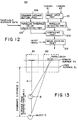
- FIG. 12 is a system block diagram showing a construction of the distance image generating unit 64.
- the distance image generating unit 64 of this modification includes an image input part 101, a parallax detecting part 102, a comparing part 103, an image dividing part 104, a parallax threshold value calculating part 105, and a standard distance setting part 106.
- the image input part 101 receives the images from the cameras 61 and 62, and extracts images of the concerned objects.
- the parallax detecting part 102 calculates the parallax from the images of the concerned objects extracted by the image input part 101.
- the comparing part 103 compares the parallax calculated by the parallax detecting part 102 and a parallax threshold value which is calculated in advance, and obtains dividing positions.
- the image dividing part 104 divides the input image depending on the dividing positions of the input image obtained by the comparing part 103.
- the parallax threshold value calculating part 105 calculates the parallax threshold value which is supplied to the comparing part 103.
- the standard distance setting part 106 sets a standard distance for use in detecting the parallax by the parallax threshold value calculating part 105.
- the image input part 101 inputs the images picked up by the cameras 61 and 62, and extracts the concerned objects such as the players and the ball from the picked up images by carrying out an image extraction process.
- the concerned objects which are extracted by the image input part 101 are supplied to the parallax detecting part 102.
- the parallax detecting part 102 detects the parallax, that is, the difference between the positions of the concerned objects which are common to the picked up images of the cameras 61 and 62, and supplies the difference in the positions of the common concerned objects to the comparing part 103.
- FIG. 13 is a diagram for explaining a parallax detecting method of the distance image generating unit 64. If a standard distance from a lens surface S L to an object O is denoted by L and the object O moves a distance ⁇ L in a direction A along the optical axis of the camera 61, the image of the object O picked up by the camera 62 changes by ⁇ x on a sensor surface S S compared to the position of the object O located at the standard distance L. This change fix corresponds to the parallax.
- ⁇ x ⁇ d ⁇ L/(L - ⁇ L)
- FIG. 14 is a diagram showing a relationship of the parallax with respect to an image pickup distance in the modified image pickup system of FIG. 11.
- FIG. 14 shows the parallaxes ⁇ x which are obtained at the image pickup distances corresponding to the set up distances of the display screens shown in FIG. 5 when the stereo base d is 20m, the magnification of the image pickup is 1/200 and the standard distance is 50m.
- the parallax detecting part 102 it may be judged that the image should be divided so as to display the object O for which the parallax is detected by the parallax detecting part 102 on the display screen which is arranged at the position which is 42.16m from the observation position, if the parallax is between 0.19 and 0.06.
- the parallax detecting part 102 it may be judged that the image should be divided so as to display the object O for which the parallax is detected by the parallax detecting part 102 on the display screen which is arranged at the position which is 53.16m from the observation position, if the parallax is between -0.06 and -0.18.
- the comparing part 103 compares the parallax threshold value which is set in advance depending on the display screen position as shown in FIG. 14 and the parallax detected by the parallax detecting part 102, and determines the display screen which is to display the object the parallax of which is detected by the parallax detecting part 102.
- the image dividing part 104 divides the image picked up by the camera 61 or 62 at the positions determined by the comparing part 103, and transmits the divided images.
- the parallax threshold value calculating part 105 calculates and supplies the parallax threshold value which is used as a reference in the comparing part 103 for the comparison with the parallax detected by the parallax detecting part 102.
- the standard distance L (for example, 50m) which makes the parallax zero is supplied from the standard distance setting part 106 to the parallax threshold value calculating part 105.
- distance information S such as 30m, 32.3m, 35.01m, ..., and 112.2m, which indicate the positions where the display screens are set up as shown in FIG. 5, are also supplied to the parallax threshold value calculating part 105.
- the parallax threshold value calculating part 105 obtains a moving distance ⁇ L shown in FIG. 13 from the standard distance L which makes the parallax zero and is obtained from the standard distance setting part 106 and the distance information S which indicates the positions where the display screens are set up as shown in FIG. 5.
- the moving distance ⁇ L which is obtained from the formula (9) and the standard distance L supplied from the standard distance setting part 106 are substituted into the formula (8), so as to obtain and store the parallax fix corresponding to the distance information S which indicates the positions where the display screens are set up as shown in FIG. 5, for every distance S, as shown in FIG. 14.
- the stereo base d dependent on the set up states of the cameras 61 and 62 and the image pickup magnification ⁇ of the cameras 61 and 62 are prestored in the parallax threshold value calculating part 105.
- the parallax threshold value calculating part 105 calculates the formula (9) when the distance information S and the standard distance L are substituted into the formula (9), and the formula (8) is calculated based on the calculation result of the formula (9) so as to calculate the parallax threshold value.
- the image dividing part 104 divides the input image so as to display the concerned object O on the display screen arranged at the position having the set up distance of 30m.
- the image dividing part 104 divides the input image so as to display the concerned object O on the display screen arranged at the position having the set up distance of 32.3m.
- the image dividing part 104 divides the input image so as to display the concerned object O on the display screen arranged at the position having the set up distance of 35.01m, and the division and display are made similarly thereafter.
- the image dividing part 104 divides the input image so as to display the concerned object O on the display screen arranged at the position having the set up distance of 87.94m.
- the image dividing part 104 divides the input image so as to display the concerned object O on the display screen arranged at the position having the set up distance of 112.2m.
- FIG. 15 is a diagram showing a general construction of an application of the image display system according to the preferred embodiment of the present invention.
- those parts which are the same as those corresponding parts in FIG. 2 are designated by the same reference numerals, and a description thereof will be omitted.
- a game that is played in a stadium A is displayed three-dimensionally in another stadium B so that the game can be seen in the other stadium B.
- the image input device 51 described above is provided in the stadium A, and picks up the image of the game that is played in the stadium A as shown in FIG. 3(A), for example.
- the picked up image 13 is supplied to the image dividing unit 12, and is divided into the rectangular images 13-1 through 13-n as shown in FIG. 3(B) to be displayed at the positions corresponding to the plurality of display units 11-1 through 11-n which are arranged in the stadium B.
- the plurality of rectangular images 13-1 through 13-n divided in the image dividing unit 12 are supplied to a transmitting unit 71 and are transmitted by, for example, radio transmission.
- the plurality of rectangular images 13-1 through 13-n transmitted from the transmitting unit 71 are received by a receiving unit 72 provided at the stadium B.
- the plurality of rectangular images 13-1 through 13-n received by the receiving unit 72 are supplied to an image distributing unit 73.
- the image distributing unit 73 distributes the plurality of rectangular images 13-1 through 13-n to the plurality of display units 11-1 through 11-n which are arranged in the field 22 of the stadium 22.
- the game that is actually being played in the stadium A can be seen in the other stadium B as if the game were being played in this other stadium B.
- FIG. 16 is a diagram showing a general construction of an image display system according to another preferred embodiment of the present invention.
- those parts which are the same as those corresponding parts in FIG. 2 are designated by the same reference numerals, and a description thereof will be omitted.
- a display unit 11-n+ 1 having a screen Sn+1 which covers the back (outfield) stand 23 is arranged behind the display unit 11-n.
- the display unit 11-n+1 receives the image of the background portion from the image dividing unit 12, and displays the background.
- it is possible to further improve the real life presence effect by providing the display unit 11-n+1 which has the screen Sn+1 for displaying the background in front of the back (outfield) stand 23, so as to display the image of the back (outfield) stand which is the background portion of the field of the stadium A where the actual game is picked up.
- the image existing nearby is displayed on the display means arranged near the observer, and the image existing far away is displayed on the display means arranged far away from the observer. For this reason, the observer can recognize the images displayed on the plurality of display means as a three-dimensional image.
- adjacent display means of the plurality of display means are set at intervals proportional to the distances from the observation position, so that it is possible to reduce the number of display means without deteriorating the depth perception and to simplify the system structure.
- a plurality of display means are set at intervals matching the depth perception of the human eyes, by arranging the plurality of display means at intervals proportional to the squares of the distances from the observation position. For this reason, it is possible to reduce the number of display means without deteriorating the depth perception and to simplify the system structure.
- the resolving power of the human eyes becomes poorer as the distance from the observation position becomes longer, and thus, the displayed images do not become unnatural to the human eyes even if the pixel pitches of the display means located far away from the observation position is set coarse.
- the images projected from the projector are output to diffusing means to be displayed thereon, it is possible to form a large screen using a relatively simple construction, and the system structure can be simplified.
- the diffusing means includes transmitting and diffusing means which switch between diffusing and transmitting states, and the switch control means successively switches the transmitting and diffusing means to the diffusing state, it is possible for the observer to positively recognize the overlapping image portions even when the displayed images overlap between adjacent diffusing means. As a result, it is possible to display the images with real life presence across the plurality of display means.
- the images are detected by first and second image input means, a parallax is detected from the two input images, and the display means for making the display are divided depending on the detected parallax.
Landscapes
- Engineering & Computer Science (AREA)
- Multimedia (AREA)
- Signal Processing (AREA)
- Testing, Inspecting, Measuring Of Stereoscopic Televisions And Televisions (AREA)
- Studio Devices (AREA)
Applications Claiming Priority (3)
| Application Number | Priority Date | Filing Date | Title |
|---|---|---|---|
| JP56386/97 | 1997-03-11 | ||
| JP5638697 | 1997-03-11 | ||
| JP5638697 | 1997-03-11 |
Publications (2)
| Publication Number | Publication Date |
|---|---|
| EP0865201A2 true EP0865201A2 (fr) | 1998-09-16 |
| EP0865201A3 EP0865201A3 (fr) | 2000-12-27 |
Family
ID=13025820
Family Applications (1)
| Application Number | Title | Priority Date | Filing Date |
|---|---|---|---|
| EP97309260A Withdrawn EP0865201A3 (fr) | 1997-03-11 | 1997-11-18 | Système d'affichage d'image |
Country Status (2)
| Country | Link |
|---|---|
| US (1) | US6262694B1 (fr) |
| EP (1) | EP0865201A3 (fr) |
Cited By (1)
| Publication number | Priority date | Publication date | Assignee | Title |
|---|---|---|---|---|
| EP1505829A1 (fr) * | 2003-08-08 | 2005-02-09 | Ben Kutner | Simulation de la présence à un évènement réel |
Families Citing this family (23)
| Publication number | Priority date | Publication date | Assignee | Title |
|---|---|---|---|---|
| US6525699B1 (en) * | 1998-05-21 | 2003-02-25 | Nippon Telegraph And Telephone Corporation | Three-dimensional representation method and an apparatus thereof |
| US7730413B1 (en) * | 1999-08-19 | 2010-06-01 | Puredepth Limited | Display method for multiple layered screens |
| JP3478192B2 (ja) * | 1999-08-20 | 2003-12-15 | 日本電気株式会社 | 画面重畳表示型情報入出力装置 |
| JP3518465B2 (ja) * | 2000-02-18 | 2004-04-12 | 日本電気株式会社 | 被写体抽出装置、被写体抽出方法、及び被写体抽出プログラムを記録した記録媒体 |
| US6879322B2 (en) * | 2000-05-30 | 2005-04-12 | Fujitsu Limited | Three-dimensional object display system, three-dimensional object display method and recording medium recording a three-dimensional object display program |
| GB2370709A (en) * | 2000-12-28 | 2002-07-03 | Nokia Mobile Phones Ltd | Displaying an image and associated visual effect |
| US7619585B2 (en) * | 2001-11-09 | 2009-11-17 | Puredepth Limited | Depth fused display |
| US7098868B2 (en) * | 2003-04-08 | 2006-08-29 | Microsoft Corporation | Display source divider |
| US8585479B2 (en) | 2003-10-20 | 2013-11-19 | Tipping Point Group, Llc | System to decode video signal from electronic gaming device and to determine play information |
| WO2005104545A2 (fr) * | 2004-04-19 | 2005-11-03 | The Trustees Of Columbia University In The City Of New York | Procedes et systemes permettant d'afficher des images tridimensionnelles |
| US7614748B2 (en) * | 2004-10-25 | 2009-11-10 | The Trustees Of Columbia University In The City Of New York | Systems and methods for displaying three-dimensional images |
| US7548662B2 (en) * | 2005-01-21 | 2009-06-16 | Microsoft Corporation | System and process for increasing the apparent resolution of a display |
| US7651282B2 (en) * | 2005-05-04 | 2010-01-26 | The Trustees Of Columbia University In The City Of New York | Devices and methods for electronically controlling imaging |
| JP2007017768A (ja) * | 2005-07-08 | 2007-01-25 | Hitachi Displays Ltd | 表示装置 |
| US20070104392A1 (en) * | 2005-11-07 | 2007-05-10 | Chi Lin Technology Co., Ltd. | Image enlarging method and TV wall using the same |
| US8425318B2 (en) * | 2008-08-21 | 2013-04-23 | Wms Gaming, Inc. | Multiple wagering game displays from single input |
| KR101652471B1 (ko) * | 2009-06-16 | 2016-08-30 | 삼성전자주식회사 | 영상 표시 장치 및 방법 |
| JP5364666B2 (ja) * | 2010-09-13 | 2013-12-11 | 株式会社東芝 | 立体画像表示装置、方法およびプログラム |
| US9406253B2 (en) * | 2013-03-14 | 2016-08-02 | Broadcom Corporation | Vision corrective display |
| CN103473692A (zh) * | 2013-06-17 | 2013-12-25 | 展讯通信(上海)有限公司 | 一种三维购物平台显示系统 |
| US10216523B2 (en) | 2015-07-17 | 2019-02-26 | General Electric Company | Systems and methods for implementing control logic |
| CN106803234B (zh) * | 2015-11-26 | 2020-06-16 | 腾讯科技(深圳)有限公司 | 图片编辑中的图片显示控制方法及装置 |
| JP2018169517A (ja) * | 2017-03-30 | 2018-11-01 | ソニーセミコンダクタソリューションズ株式会社 | 撮像装置、撮像モジュールおよび撮像装置の制御方法 |
Citations (6)
| Publication number | Priority date | Publication date | Assignee | Title |
|---|---|---|---|---|
| US4190856A (en) * | 1977-11-21 | 1980-02-26 | Ricks Dennis E | Three dimensional television system |
| WO1991015930A2 (fr) * | 1990-04-05 | 1991-10-17 | Raychem Corporation | Affichage tridimensionnel |
| US5086354A (en) * | 1989-02-27 | 1992-02-04 | Bass Robert E | Three dimensional optical viewing system |
| FR2672397A1 (fr) * | 1991-02-04 | 1992-08-07 | Duplat Bertrand | Procede de projection en relief. |
| DE4300246A1 (en) * | 1992-01-08 | 1993-07-15 | Terumo Corp | Depth scanner for displaying three=dimensional pictures without lenses - projects collimated light through object to be scanned and condenses light and filters to remove direct flow component |
| WO1996027992A2 (fr) * | 1995-03-08 | 1996-09-12 | Philips Electronics N.V. | Systeme d'affichage d'image tridimensionnelle |
Family Cites Families (11)
| Publication number | Priority date | Publication date | Assignee | Title |
|---|---|---|---|---|
| US5105183A (en) * | 1989-04-27 | 1992-04-14 | Digital Equipment Corporation | System for displaying video from a plurality of sources on a display |
| JP2625038B2 (ja) | 1991-01-31 | 1997-06-25 | 三菱鉛筆株式会社 | エタノール系マーキングインキ組成物 |
| FR2679327B1 (fr) * | 1991-07-15 | 1996-12-27 | Cebelor | Procede de mesure tridimensionnelle, sans contact, de l'enveloppe d'un objet, notamment un pied, et appareil de mesure permettant la mise en óoeuvre du procede. |
| SE500028C2 (sv) * | 1992-12-09 | 1994-03-21 | Celsiustech Electronics Ab | Anordning för presentation av en tredimensionell bild |
| GB9314717D0 (en) * | 1993-07-15 | 1993-08-25 | Philips Electronics Uk Ltd | Image processing |
| US5805117A (en) * | 1994-05-12 | 1998-09-08 | Samsung Electronics Co., Ltd. | Large area tiled modular display system |
| US5757954A (en) * | 1994-09-20 | 1998-05-26 | Neopath, Inc. | Field prioritization apparatus and method |
| US5790086A (en) * | 1995-01-04 | 1998-08-04 | Visualabs Inc. | 3-D imaging system |
| US5886675A (en) * | 1995-07-05 | 1999-03-23 | Physical Optics Corporation | Autostereoscopic display system with fan-out multiplexer |
| US5973831A (en) * | 1996-01-22 | 1999-10-26 | Kleinberger; Paul | Systems for three-dimensional viewing using light polarizing layers |
| US5781229A (en) * | 1997-02-18 | 1998-07-14 | Mcdonnell Douglas Corporation | Multi-viewer three dimensional (3-D) virtual display system and operating method therefor |
-
1997
- 1997-10-22 US US08/955,599 patent/US6262694B1/en not_active Expired - Fee Related
- 1997-11-18 EP EP97309260A patent/EP0865201A3/fr not_active Withdrawn
Patent Citations (6)
| Publication number | Priority date | Publication date | Assignee | Title |
|---|---|---|---|---|
| US4190856A (en) * | 1977-11-21 | 1980-02-26 | Ricks Dennis E | Three dimensional television system |
| US5086354A (en) * | 1989-02-27 | 1992-02-04 | Bass Robert E | Three dimensional optical viewing system |
| WO1991015930A2 (fr) * | 1990-04-05 | 1991-10-17 | Raychem Corporation | Affichage tridimensionnel |
| FR2672397A1 (fr) * | 1991-02-04 | 1992-08-07 | Duplat Bertrand | Procede de projection en relief. |
| DE4300246A1 (en) * | 1992-01-08 | 1993-07-15 | Terumo Corp | Depth scanner for displaying three=dimensional pictures without lenses - projects collimated light through object to be scanned and condenses light and filters to remove direct flow component |
| WO1996027992A2 (fr) * | 1995-03-08 | 1996-09-12 | Philips Electronics N.V. | Systeme d'affichage d'image tridimensionnelle |
Cited By (1)
| Publication number | Priority date | Publication date | Assignee | Title |
|---|---|---|---|---|
| EP1505829A1 (fr) * | 2003-08-08 | 2005-02-09 | Ben Kutner | Simulation de la présence à un évènement réel |
Also Published As
| Publication number | Publication date |
|---|---|
| EP0865201A3 (fr) | 2000-12-27 |
| US6262694B1 (en) | 2001-07-17 |
Similar Documents
| Publication | Publication Date | Title |
|---|---|---|
| EP0865201A2 (fr) | Système d'affichage d'image | |
| EP1421797B1 (fr) | Affichage autostereoscopique s'adaptant a l'observateur | |
| US6798409B2 (en) | Processing of images for 3D display | |
| US5546120A (en) | Autostereoscopic display system using shutter and back-to-back lenticular screen | |
| US6307585B1 (en) | Position-adaptive autostereoscopic monitor (PAM) | |
| US6326994B1 (en) | Matched field-of-view stereographic imaging apparatus | |
| US4649425A (en) | Stereoscopic display | |
| KR101195929B1 (ko) | 멀티 채널 영상 시스템 | |
| JP4937424B1 (ja) | 立体画像表示装置および方法 | |
| US20060203085A1 (en) | There dimensional image signal producing circuit and three-dimensional image display apparatus | |
| JPH09121370A (ja) | 立体tv装置 | |
| KR101852209B1 (ko) | 자동입체 디스플레이 및 그 제조방법 | |
| JP3569522B2 (ja) | 表示装置 | |
| KR100786861B1 (ko) | 입체 영상 디스플레이 장치 | |
| RU2397524C2 (ru) | Камера фиксирования объемного изображения | |
| DE19500699A1 (de) | Personen-adaptiver stereoskoper Video-Schirm (PASS) | |
| WO2001013645A2 (fr) | Systeme de radiodiffusion a bande passante etroite | |
| JPH06148763A (ja) | 多人数観測用レンチキュラ立体表示方式 | |
| KR101691292B1 (ko) | Table-top 3D 디스플레이 시스템 및 그 방법 | |
| EP0655147B1 (fr) | Appareil de visualisation comprenant un appareil de commande | |
| Hirayama et al. | Flatbed-type auto stereoscopic display systems using integral imaging method | |
| JPH08313825A (ja) | 内視鏡装置 | |
| CN110115023A (zh) | 全景摄像机 | |
| JP3454798B2 (ja) | 立体映像表示装置における頭部位置検出装置の設定方法および頭部位置検出装置 | |
| JP5422684B2 (ja) | 立体画像決定装置、立体画像決定方法、および立体画像表示装置 |
Legal Events
| Date | Code | Title | Description |
|---|---|---|---|
| PUAI | Public reference made under article 153(3) epc to a published international application that has entered the european phase |
Free format text: ORIGINAL CODE: 0009012 |
|
| AK | Designated contracting states |
Kind code of ref document: A2 Designated state(s): DE FR GB |
|
| AX | Request for extension of the european patent |
Free format text: AL;LT;LV;MK;RO;SI |
|
| PUAL | Search report despatched |
Free format text: ORIGINAL CODE: 0009013 |
|
| AK | Designated contracting states |
Kind code of ref document: A3 Designated state(s): AT BE CH DE DK ES FI FR GB GR IE IT LI LU MC NL PT SE |
|
| AX | Request for extension of the european patent |
Free format text: AL;LT;LV;MK;RO;SI |
|
| RIC1 | Information provided on ipc code assigned before grant |
Free format text: 7H 04N 5/262 A, 7G 02B 27/22 B, 7H 04N 13/00 B |
|
| 17P | Request for examination filed |
Effective date: 20010226 |
|
| AKX | Designation fees paid |
Free format text: DE FR GB |
|
| 17Q | First examination report despatched |
Effective date: 20061221 |
|
| STAA | Information on the status of an ep patent application or granted ep patent |
Free format text: STATUS: THE APPLICATION IS DEEMED TO BE WITHDRAWN |
|
| 18D | Application deemed to be withdrawn |
Effective date: 20070703 |