EP0864951A1 - Armoire électrique avec dispositif de commande centrale pour la surveillance et la commande d'unités integrées et/ou séparées - Google Patents
Armoire électrique avec dispositif de commande centrale pour la surveillance et la commande d'unités integrées et/ou séparées Download PDFInfo
- Publication number
- EP0864951A1 EP0864951A1 EP98200489A EP98200489A EP0864951A1 EP 0864951 A1 EP0864951 A1 EP 0864951A1 EP 98200489 A EP98200489 A EP 98200489A EP 98200489 A EP98200489 A EP 98200489A EP 0864951 A1 EP0864951 A1 EP 0864951A1
- Authority
- EP
- European Patent Office
- Prior art keywords
- control
- output
- monitoring
- central control
- control device
- Prior art date
- Legal status (The legal status is an assumption and is not a legal conclusion. Google has not performed a legal analysis and makes no representation as to the accuracy of the status listed.)
- Granted
Links
Images

Classifications
-
- G—PHYSICS
- G05—CONTROLLING; REGULATING
- G05B—CONTROL OR REGULATING SYSTEMS IN GENERAL; FUNCTIONAL ELEMENTS OF SUCH SYSTEMS; MONITORING OR TESTING ARRANGEMENTS FOR SUCH SYSTEMS OR ELEMENTS
- G05B15/00—Systems controlled by a computer
- G05B15/02—Systems controlled by a computer electric
-
- G—PHYSICS
- G05—CONTROLLING; REGULATING
- G05B—CONTROL OR REGULATING SYSTEMS IN GENERAL; FUNCTIONAL ELEMENTS OF SUCH SYSTEMS; MONITORING OR TESTING ARRANGEMENTS FOR SUCH SYSTEMS OR ELEMENTS
- G05B2219/00—Program-control systems
- G05B2219/20—Pc systems
- G05B2219/26—Pc applications
- G05B2219/2642—Domotique, domestic, home control, automation, smart house
Definitions
- the invention relates to a control cabinet with a central Control device for monitoring and controlling installation units and / or add-on units of the control cabinet in a specifiable manner.
- a control cabinet as specified in DE 33 26 977 C2 is e.g. an installation or add-on unit in the form of an air conditioning assembly monitored and controlled, especially regulated.
- an air conditioning assembly monitored and controlled, especially regulated.
- Such a cabinet can only be air-conditioned globally for the whole Cabinet volume can be regulated and tailored to special requirements not only in terms of air conditioning, but also in terms of other functions of the control cabinet are not possible.
- the invention has for its object to provide a control cabinet, the one with simple programmability in terms of monitoring and control various adaptation options to different operating conditions offers, the structure is simple and clear.
- the information from and to different monitoring and control assemblies is therefore brought together in a central control device which has components of a personal computer.
- the states of the various built-in units or add-on units of the control cabinet can be individually adjusted, depending on each other, to the given conditions of use of the control cabinet. In this way, the control cabinet can be easily adapted to very different requirements both inside and outside, the required conditions being reliably monitored and maintained.
- Standard software can be used with the components of the personal computer and standardized interfaces can be used. Programming does not have to be at assembly level, but can be done with higher programming languages so that the user does not have to familiarize himself with a special programming language.
- the user programs can be adopted from the personal computer or developed on this. Library elements can be used for the input / output, which enable simple programming.
- the hardware for connecting a bus in particular an I 2 C bus, can also be taken over by the personal computer.
- An advantageous structure of the central control device is that the components a personal computer-typical microprocessor, a personal computer standard operating system and one compatible with this command processor as well as driver units. These components can be arranged on a motherboard and take up little space. Since the Control functions run automatically once they are programmed there is no need to install a display and keyboard. Is a further programming required, this can be done simply by that temporarily via a driver unit and an appropriate interface an independent personal computer or the like is connected.
- the Control device has an application program part with which the Monitoring, control and / or regulation data can be determined, i.e. can be specified and / or calculated.
- the driver units an input / output driver via which sensors can be queried, a driver for a serial interface, above the peripheral devices including an independent personal computer can be coupled, and have a network driver, via which the control device to a Data bus can be connected.
- the monitoring modules include a sensor device with optionally at least one humidity sensor, a door limit switch, a temperature sensor, a vibration sensor, a smoke sensor, a current transducer, a voltage transducer, a customer temperature sensor, have a code lock and / or a card reader. This allows different types of information regarding different Operating conditions and safety measures obtained and evaluated will.
- the signal transmission and processing is simple executed if it is provided that the sensor device via an input interface with the central control device in bidirectional Connection is established.
- the functional reliability of the entire monitoring system is ensured by the measures improved that the monitoring modules a function monitoring with a voltage supply device and an operating value monitor have that on failure of a normal supply Emergency supply is switched to maintain programmed emergency functions obtained, and that the central control device is buffered separately.
- the air conditioning system is simple and in terms of control and regulation clearly organized by the measures that the control modules have a regulation and control interface, on the one hand with the central control device and on the other hand with an air conditioning device optionally at least one heat exchanger, one fan, a cooling device, a heater, a door magnet and / or a customer fan includes that the signals required for regulation and control can be generated in the regulation and control interface and that the air conditioning device corresponding to signals from the central control device is controllable.
- Control modules have an output interface, on the one hand with the central control device is in a bidirectional connection and on the other hand is connected to an output device that the output device optionally at least one parallel output, one relay, one Optocoupler, a bus system output, a telemetry output, a network output, a PC interface output, an analog signal output, a display device, a light-emitting diode display and / or a symbol display unit with symbol display elements and that in the output interface Signals from the central control device for addressing the Output device are deformable.
- control buttons, a Programming, setting and testing device and / or a control center bidirectional are connected and that with the programming, setting and testing facility stored test procedures can be called up, certain program parts can be changed and / or customer-specific reference values can be entered at any time a simple way to perform a function test and change the set parameters, such as. Temperature setting values. To this An adjustment to changed conditions is also easily possible.
- a clear structure is further favored by the fact that the central Control device is built on a motherboard and that all Einund Outputs can be linked together.
- the sensor device 1 shows an overall monitoring device 10 for a control cabinet with a sensor device 1, an air conditioning device 2, one Communication device 3, an output device 4, a function monitoring 5 and a central control device 6.
- the sensor device 1 is via an input interface 1.10 with the central control device 6 connected, the connection between the input interface 1.10 and the central control device 6 bidirectionally is trained.
- the sensor device 1 comprises a moisture sensor 1.1, one Door limit switch 1.2, a temperature sensor 1.3, a vibration sensor 1.4, a smoke sensor 1.5, a current transducer 1.6, a voltage transducer 1.7, a code lock 1.8 and a card reader 1.9.
- the input interface 1.10 is preferably built on a circuit board and on one side a voltage supply for the sensor device 1 according to the requirements of the individual components safely, with direct and alternating voltages can be provided, and on the other hand processes the signals supplied by the individual components of the sensor device 1 and reshapes it so that it is forwarded to the central control device 6 can be. It can also evaluate and weight the Signals as well as a logical link are carried out.
- the air conditioning device 2 has one Heat exchanger 2.1, a fan 2.2, a cooling device 2.3, a heater 2.4, a door magnet 2.5 and a regulation and control interface 2.6.
- the regulation and control interface 2.6 is on the one hand with the central Control device 6 and on the other hand with the components mentioned Air conditioning device 2 each in a bidirectional connection. With the help of Regulation and control interface 2.6 become the connected components the air conditioning device 2 in accordance with the signals of central control device 6 controlled. As a result of the bidirectional In addition to the control or regulation, there is also the possibility of connection the function monitoring of the air conditioning device 2 with its individual Components.
- the fan 2.2 and possibly a customer fan can be AC or DC versions.
- the air conditioning device 2 advantageously comprises also compressors, pneumatic or hydraulic valves, Humidification and dehumidification devices, pressure sensors and air flow monitoring devices. The individual components of the air conditioning system 2 can be present, controlled and according to the respective need be managed.
- the communication device 3 comprises control buttons 3.1 and a programming, Adjustment and test equipment 3.2 and possibly a control center.
- the Programming, setting and testing device 3.2 can, for example, via a Hand module (not shown) can be operated. With the programming, setting and Test facility 3.2 can both permanently stored test procedures be called when certain program parts are changed (e.g. subsequent change of temperature setting values). Furthermore, customer side Reference values (e.g. for calibration) can be entered. over the control center can control the operating status of the monitoring personnel and be adjusted if necessary.
- the output device 4 comprises a parallel output 4.1, an optocoupler and / or relay 4.2, a bus system output 4.3, a telemetry output 4.4, a network output 4.5, a PC interface output 4.6, possibly an analog signal output, a display device 4.7, a light-emitting diode display 4.8, a symbol display unit with symbol display elements 4.9 and an output interface 4.10.
- the output interface 4.10 is bidirectional Connection to the central control device 6. With the help the output section 4.10 can information signals in various Form are output as the various components of the output device 4 show. For example, via the telemetry output 4.4 Data are transmitted to a remote monitoring station. Via the relay 4.2 or the optocoupler 4.2, e.g.
- the bus system output 4.3 can e.g. one Fieldbus or the like. Include.
- the PC interface output 4.6 can e.g. as RS 232 interface or the like. Be formed.
- As a display device 4.7 can other suitable display units, e.g. LCD units or the like be.
- the analog signal output can be used as a voltage or current output be executed.
- the function monitoring includes an emergency supply 5.1, a normal supply 5.2 and monitoring of operating values 5.3.
- Emergency care 5.1 e.g. a battery-backed power supply for the overall monitoring device 10 which programmed certain in the event of a power failure Maintains emergency functions in the event of a power failure.
- the normal care 5.2 especially mains voltage supply, is constantly monitored, to switch directly to emergency care 5.1 in an emergency.
- the Central control device 6, which is preferably on a motherboard is built up, is buffered separately again.
- the operational monitoring 5.3 serves both as a memory for an operational data acquisition (e.g. run times), as well as an error memory for in operation errors or faults that have occurred that have reset themselves.
- the various Devices of the overall monitoring device 10 can, if appropriate, additional or different components can be provided.
- Connection to the respective interface or the connection to the central one Control device 6 easily possible and the adaptation by appropriate simple reprogramming of the central control device 6 also easy to do.
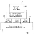
- the central control device 6 built on the main board is based advantageous on a system with components 6.1 to 6.6 of a personal computer (PC), as shown schematically in Fig. 2.
- PC personal computer
- memory chips e.g. an Eprom or EEprom
- the PC components 6.1 to 6.6. allow easy operation when programming the desired Control processes and settings.
- a PC-specific central processor 6.1 contains a in a known manner Micro program for the initial charge from a read-only memory. After the first charge takes over the operating system provided in an operating system unit 6.2 its function and an established command processor automatically loaded. An application program is created by means of the command processor loaded from an application program area 6.6, which the programmed Monitoring, control and regulation processes and given conditions and set values are taken into account and any necessary data is calculated. For example, due to a specific reaction sequence takes place in the application program, when a signal arrives from a door limit switch 1.2. In this case, a Alarm triggered and / or the air conditioning device 2 switched off or according to a further program on one intended for this case Operation can be reversed. In a similar way, specific control procedures when other sensor signals arrive using the application program be specified.
- the sensors are in particular at one Input / output driver 6.3 and are coupled according to the application program and the operating system, and their Sensor signals evaluated.
- a driver 6.4 for a serial interface can in particular peripheral units can be connected, for example an independent one Personal computer with screen and keyboard for programming the central Control device 6.
- a connection can be made via a network driver 6.5
- An external bus system can be produced, for example, the data of several such control cabinets in a central data processing system evaluate.
- the drivers in standard software form a connection between application program and operating system and reduce the programming effort for coupling and monitoring, control and regulation the installation units and add-on units.
- control cabinet monitoring system enables many monitoring and control functions. For example, a door and trim parts inspection be carried out by several door limit switches 1.2 are looped. If the loop is interrupted, a signal is generated issued, which indicates an open state.
- the door limit switch 1.2 can also be designed as a magnetic contact that consists of a magnet on the movable Part and a read relay on the fixed part.
- a legitimation check can be provided with a coding lock, a magnetic card reader, a chip card reader, a punch card reader, non-contact magnetic card recognition, voice recognition, a portrait recognition and / or a hand or fingerprint recognition.
- Valid Identifiers are stored in a reader and are activated when actuated compared to the input. If the comparison is positive, it becomes a valid one Message via the interface and, if the comparison is negative, an invalid message submitted.
- storing the valid identifiers in the overall monitoring system 10 is input via an interface to a Given evaluation unit and compared there.
- Proximity control can also be provided. With motion detectors an approximation is recognized on the basis of infrared, ultrasound or radar. The Entering near the cabinet can be determined by induction loops. The area around the control cabinet can also be protected with light barriers will. In order to register the approach of a person, foot contacts can be made also laid in mats in front of, next to or behind the control cabinet will. If an approximation has been recognized, the central Control device 6 triggered an acoustic or visual alarm and can also be passed on and logged via an interface.
- the cause can be a smoldering fire in the cable insulation, which usually consists of PVC and triggers a risk of dioxins. Plastic parts or paper can also burn during printer operation.
- the smoke sensor 1.5 or smoke detector detects smoke and soot particles and emits a signal to the central control device 6, which triggers a programmed reaction. It can be provided that the reaction is triggered after a time delay to be defined after one or more checks of the signal of the smoke sensor 1.5. If the signal is no longer present, a false alarm can be assumed. The process is then only logged. If the alarm is valid, the voltage to the installed components must be switched off.
- the central control device 6 can be configured in such a way that the fans are switched off after the alarm, so that the installation room is less smoky. In special cases, suctioning out of the cabinet can be useful. The fans must be switched on for this. Motorized ventilation flaps can be used to close the ventilation openings in the event of an alarm. In special cases, opening may make sense. The door lock is released. Setting a high priority and triggering the alarm via as many outputs as possible can be advisable (collective fault message, network connection, serial or parallel interfaces). The alarm can be integrated into the normal fire alarm systems, whereby a position specification and measures are selected. Automatic fire extinguishing systems in the control cabinet are activated. A water spray system installed in the cabinet is opened.
- a pressurized container with a fire extinguishing agent for example CO 2
- a fire extinguishing agent for example CO 2
- the pressure created in the control cabinet when extinguishing can escape by opening motor-operated flaps or automatically opening flaps, which may be unlocked. Escaping via controlled deformation of the paneling is also possible. Forced ventilation of the control cabinet to the outside can be provided.
- the given via the central control device 6 can be just as varied Functions also for other sensor signals.
- the bidirectional network output or a corresponding connection can also voice and Image data are transmitted. This is e.g. a communication between Network supervisor and network technician possible.
Applications Claiming Priority (2)
| Application Number | Priority Date | Filing Date | Title |
|---|---|---|---|
| DE19710019A DE19710019C2 (de) | 1996-03-13 | 1997-03-12 | Schaltschrank mit einer zentralen Steuerungseinrichtung zum Überwachen, Steuern und/oder Regeln von Einbau- und/oder Anbaueinheiten |
| DE19710019 | 1997-03-12 |
Publications (2)
| Publication Number | Publication Date |
|---|---|
| EP0864951A1 true EP0864951A1 (fr) | 1998-09-16 |
| EP0864951B1 EP0864951B1 (fr) | 2001-06-13 |
Family
ID=7822991
Family Applications (1)
| Application Number | Title | Priority Date | Filing Date |
|---|---|---|---|
| EP98200489A Expired - Lifetime EP0864951B1 (fr) | 1997-03-12 | 1998-02-13 | Armoire électrique avec dispositif de commande centrale pour la surveillance et la commande d'unités integrées et/ou séparées |
Country Status (4)
| Country | Link |
|---|---|
| US (1) | US6222448B1 (fr) |
| EP (1) | EP0864951B1 (fr) |
| JP (1) | JP3142812B2 (fr) |
| ES (1) | ES2159168T3 (fr) |
Cited By (1)
| Publication number | Priority date | Publication date | Assignee | Title |
|---|---|---|---|---|
| CN102183949A (zh) * | 2011-02-28 | 2011-09-14 | 中国北方车辆研究所 | 一种优化级联的复用式智能模拟负载实现方法 |
Families Citing this family (36)
| Publication number | Priority date | Publication date | Assignee | Title |
|---|---|---|---|---|
| DE19609689B4 (de) * | 1996-03-13 | 2006-01-26 | Rittal Gmbh & Co. Kg | Schaltschrank mit einer zentralen Steuerungseinrichtung zum Überwachen, Steuern und/oder Regeln von Einbau- und/oder Anbaueinheiten |
| DE19911310A1 (de) * | 1999-03-13 | 2000-09-21 | Loh Kg Rittal Werk | Schaltschranküberwachungseinrichtung |
| DE19911320A1 (de) * | 1999-03-13 | 2000-09-21 | Loh Kg Rittal Werk | Schaltschranküberwachungseinrichtung |
| DE19911824C2 (de) * | 1999-03-17 | 2001-12-20 | Loh Kg Rittal Werk | Schaltschranküberwachungsanlage |
| KR19990083691A (ko) * | 1999-05-28 | 1999-12-06 | 김원선 | 전극봉식가습제어를포함한항온항습기제어용마이컴컨트롤러 |
| DE19933086B4 (de) * | 1999-07-15 | 2008-11-20 | Robert Bosch Gmbh | Verfahren und Vorrichtung zur gegenseitigen Überwachung von Steuereinheiten |
| US6935946B2 (en) * | 1999-09-24 | 2005-08-30 | Igt | Video gaming apparatus for wagering with universal computerized controller and I/O interface for unique architecture |
| US6866581B2 (en) * | 1999-09-24 | 2005-03-15 | Igt | Video gaming apparatus for wagering with universal computerized controller and I/O interface for unique architecture |
| DE10007270A1 (de) * | 2000-02-17 | 2001-11-29 | Loh Kg Rittal Werk | Schaltschrankklimatisierungseinrichtung |
| CA2402389A1 (fr) * | 2000-03-08 | 2002-09-19 | Shuffle Master, Inc. | Systeme de jeu informatise, procede d'utilisation et appareil |
| US7043641B1 (en) * | 2000-03-08 | 2006-05-09 | Igt | Encryption in a secure computerized gaming system |
| US7988559B2 (en) * | 2001-03-08 | 2011-08-02 | Igt | Computerized gaming system, method and apparatus |
| DE10042165C1 (de) * | 2000-08-17 | 2002-04-18 | Butzke Werke Aqua | System zur Steuerung und Überwachung von Sanitärarmaturen |
| DE10108599C2 (de) * | 2001-02-22 | 2003-04-30 | Rittal Gmbh & Co Kg | Schaltschrank oder Schaltschrankanordnung mit einer darin angeordneten Überwachungseinrichtung |
| US7203841B2 (en) * | 2001-03-08 | 2007-04-10 | Igt | Encryption in a secure computerized gaming system |
| DE10113627B4 (de) * | 2001-03-20 | 2005-12-29 | Rittal Gmbh & Co. Kg | Schaltschranküberwachungseinrichtung |
| DE10113626A1 (de) * | 2001-03-20 | 2002-10-02 | Rittal Gmbh & Co Kg | Schaltschrank oder Schaltschrankanordnung mit einer darin angeordneten Überwachungseinrichtung |
| DE10119637A1 (de) * | 2001-04-20 | 2002-11-21 | Rittal Gmbh & Co Kg | Schaltschrank-Überwachungssystem |
| CA2460046C (fr) * | 2001-09-10 | 2014-06-10 | Igt | Mise au point de programmes de jeu compatibles avec un systeme et un dispositif d'exploitation de jeu electronique |
| US7931533B2 (en) | 2001-09-28 | 2011-04-26 | Igt | Game development architecture that decouples the game logic from the graphics logics |
| US8708828B2 (en) | 2001-09-28 | 2014-04-29 | Igt | Pluggable modular gaming modifiers and configuration templates for gaming environments |
| US6902481B2 (en) | 2001-09-28 | 2005-06-07 | Igt | Decoupling of the graphical presentation of a game from the presentation logic |
| US7340311B2 (en) * | 2002-03-19 | 2008-03-04 | Richard Landis | Electrical panel access and control apparatus including true emergency stop and power buss lockout |
| US20030203755A1 (en) * | 2002-04-25 | 2003-10-30 | Shuffle Master, Inc. | Encryption in a secure computerized gaming system |
| WO2004068614A2 (fr) * | 2003-01-24 | 2004-08-12 | Tecumseh Products Company | Systeme de commande et de protection de cvcr integre |
| US7623028B2 (en) | 2004-05-27 | 2009-11-24 | Lawrence Kates | System and method for high-sensitivity sensor |
| DE102005002314A1 (de) * | 2005-01-17 | 2006-07-27 | Rittal Gmbh & Co. Kg | Schaltschranksteuerungs- und Überwachungssystem |
| DE102008012097B4 (de) * | 2008-02-29 | 2013-02-28 | Rittal Gmbh & Co. Kg | Überwachungseinrichtung für den Betrieb von Schaltschrankgeräten |
| US8184014B2 (en) | 2008-06-27 | 2012-05-22 | Schlumberger Technology Corporation | Driver to transmit signals over a transmission line in a well |
| US8981945B2 (en) | 2009-07-08 | 2015-03-17 | Abb Research Ltd. | Bus condition monitoring system |
| US8463453B2 (en) | 2009-11-13 | 2013-06-11 | Leviton Manufacturing Co., Inc. | Intelligent metering demand response |
| US8755944B2 (en) * | 2009-11-13 | 2014-06-17 | Leviton Manufacturing Co., Inc. | Electrical switching module |
| AT511971B1 (de) * | 2011-10-05 | 2016-02-15 | Fronius Int Gmbh | Verfahren zur überwachung einer kühl- oder heizeinrichtung und überwachungseinrichtung hierzu |
| CN102967329A (zh) * | 2012-11-08 | 2013-03-13 | 大连东方电器制造有限公司 | 开关柜监测报警装置 |
| JP6489742B2 (ja) * | 2014-01-30 | 2019-03-27 | 三菱重工業株式会社 | 空調システム及びその制御方法 |
| CN106249712A (zh) * | 2016-08-19 | 2016-12-21 | 广东锐捷安全技术股份有限公司 | 一种智能群控平台 |
Citations (4)
| Publication number | Priority date | Publication date | Assignee | Title |
|---|---|---|---|---|
| DE3326977A1 (de) * | 1983-07-27 | 1985-02-07 | Bruno 7441 Wolfschlugen Kümmerle | Kuehlaggregat fuer elektrische schaltschraenke |
| US4567557A (en) * | 1983-02-23 | 1986-01-28 | Burns Martin J | Building intelligence system |
| EP0192108A2 (fr) * | 1985-02-11 | 1986-08-27 | Rodger T. Lovrenich | Station de commande |
| US5317501A (en) * | 1987-10-13 | 1994-05-31 | Bernhard Hilpert | Control system for a numerically controlled machine |
Family Cites Families (1)
| Publication number | Priority date | Publication date | Assignee | Title |
|---|---|---|---|---|
| US5400246A (en) * | 1989-05-09 | 1995-03-21 | Ansan Industries, Ltd. | Peripheral data acquisition, monitor, and adaptive control system via personal computer |
-
1998
- 1998-02-13 ES ES98200489T patent/ES2159168T3/es not_active Expired - Lifetime
- 1998-02-13 EP EP98200489A patent/EP0864951B1/fr not_active Expired - Lifetime
- 1998-03-10 US US09/037,651 patent/US6222448B1/en not_active Expired - Fee Related
- 1998-03-11 JP JP10059536A patent/JP3142812B2/ja not_active Expired - Fee Related
Patent Citations (4)
| Publication number | Priority date | Publication date | Assignee | Title |
|---|---|---|---|---|
| US4567557A (en) * | 1983-02-23 | 1986-01-28 | Burns Martin J | Building intelligence system |
| DE3326977A1 (de) * | 1983-07-27 | 1985-02-07 | Bruno 7441 Wolfschlugen Kümmerle | Kuehlaggregat fuer elektrische schaltschraenke |
| EP0192108A2 (fr) * | 1985-02-11 | 1986-08-27 | Rodger T. Lovrenich | Station de commande |
| US5317501A (en) * | 1987-10-13 | 1994-05-31 | Bernhard Hilpert | Control system for a numerically controlled machine |
Non-Patent Citations (1)
| Title |
|---|
| "PCS AND SMART I/O INVADE PLC TERRITORY", I & CS - INDUSTRIAL AND PROCESS CONTROL MAGAZINE, vol. 68, no. 5, 1 May 1995 (1995-05-01), pages 53 - 56, XP000508356 * |
Cited By (2)
| Publication number | Priority date | Publication date | Assignee | Title |
|---|---|---|---|---|
| CN102183949A (zh) * | 2011-02-28 | 2011-09-14 | 中国北方车辆研究所 | 一种优化级联的复用式智能模拟负载实现方法 |
| CN102183949B (zh) * | 2011-02-28 | 2013-02-20 | 中国北方车辆研究所 | 一种优化级联的复用式智能模拟负载实现方法 |
Also Published As
| Publication number | Publication date |
|---|---|
| EP0864951B1 (fr) | 2001-06-13 |
| JPH1151451A (ja) | 1999-02-26 |
| JP3142812B2 (ja) | 2001-03-07 |
| ES2159168T3 (es) | 2001-09-16 |
| US6222448B1 (en) | 2001-04-24 |
Similar Documents
| Publication | Publication Date | Title |
|---|---|---|
| EP0864951B1 (fr) | Armoire électrique avec dispositif de commande centrale pour la surveillance et la commande d'unités integrées et/ou séparées | |
| DE19710019C2 (de) | Schaltschrank mit einer zentralen Steuerungseinrichtung zum Überwachen, Steuern und/oder Regeln von Einbau- und/oder Anbaueinheiten | |
| EP0886898B1 (fr) | Armoire de commande avec dispositif de controle et de commande de composants incorpores et/ou rapportes | |
| DE3803892C2 (fr) | ||
| DE102004013601A1 (de) | Bewegliches Barrierenbetriebsverfahren und Vorrichtung | |
| DE3490205C2 (fr) | ||
| WO2006074808A1 (fr) | Systeme de surveillance et de commande d'une armoire de distribution | |
| EP1847891A1 (fr) | Paramétrage sûr d'un dispositif de commutation de sécurité | |
| WO2007076939A2 (fr) | Dispositif pour commander au moins une machine | |
| DE19714838C2 (de) | Schaltschrankklimatisierungseinrichtung | |
| EP1065577B1 (fr) | Dispositif de sécurité pour au moins une porte, de préférence pour sorties de secours | |
| DE102007041383B4 (de) | Rauch- und Wärmeabzugs- und Lüftungseinrichtung umfassend Rauch- und Wärmeabzugs- und Lüftungsgeräte mit jeweils einem motorischen Antrieb | |
| DE102005031112A1 (de) | Betriebsparameter-Übertragungsverfahren für Betätigungseinheit für bewegliche Schranke und Vorrichtung | |
| EP1374001B1 (fr) | Armoire de commande ou systeme d'armoire de commande avec dispositif de controle integre | |
| EP1072743A1 (fr) | Dispositif de sortie de secours pour au moins une porte ou une fenêtre dans les sorties de secours | |
| DE19607918A1 (de) | Steuerungseinrichtung für einen motorischen Antrieb einer Tür- oder Fensteranlage | |
| DE19930690C2 (de) | Situationserfassungseinrichtung zur Blockadeerkennung bei Türen, Toren oder dergleichen | |
| DE102007011428B4 (de) | Steuereinheit für eine Rauch- und Wärmeabzugsanlage eines Gebäudes | |
| EP1760558B1 (fr) | Dispositif et procédé destinés à examiner la sécurité d'un dispositif technique | |
| DE10011763A1 (de) | Verriegelungseinrichtung für mindestens eine Tür, vorzugsweise in Flucht- und Rettungswegen | |
| WO2003085463A1 (fr) | Systeme d'entrainement a commande par moteur electrique, muni d'un systeme de securite fonctionnant des l'apparition de la premiere erreur | |
| DE102020129085A1 (de) | System zum sicherheitsgerichteten Entwärmen eines Schaltschranks | |
| DE4244012A1 (de) | Hubdach | |
| DE4445465A1 (de) | Verfahren und Vorrichtung zur Auswertung von Signalen einer Gefahrenmeldeanlage | |
| DE10207513B4 (de) | Schaltschranküberwachungs- und Schaltschranksteuerungseinrichtung |
Legal Events
| Date | Code | Title | Description |
|---|---|---|---|
| PUAI | Public reference made under article 153(3) epc to a published international application that has entered the european phase |
Free format text: ORIGINAL CODE: 0009012 |
|
| 17P | Request for examination filed |
Effective date: 19980716 |
|
| AK | Designated contracting states |
Kind code of ref document: A1 Designated state(s): ES FR GB IT |
|
| AX | Request for extension of the european patent |
Free format text: AL;LT;LV;MK;RO;SI |
|
| AKX | Designation fees paid |
Free format text: ES FR GB IT |
|
| RBV | Designated contracting states (corrected) |
Designated state(s): ES FR GB IT |
|
| REG | Reference to a national code |
Ref country code: DE Ref legal event code: 8566 |
|
| 17Q | First examination report despatched |
Effective date: 19990804 |
|
| GRAG | Despatch of communication of intention to grant |
Free format text: ORIGINAL CODE: EPIDOS AGRA |
|
| GRAG | Despatch of communication of intention to grant |
Free format text: ORIGINAL CODE: EPIDOS AGRA |
|
| GRAH | Despatch of communication of intention to grant a patent |
Free format text: ORIGINAL CODE: EPIDOS IGRA |
|
| GRAH | Despatch of communication of intention to grant a patent |
Free format text: ORIGINAL CODE: EPIDOS IGRA |
|
| GRAA | (expected) grant |
Free format text: ORIGINAL CODE: 0009210 |
|
| AK | Designated contracting states |
Kind code of ref document: B1 Designated state(s): ES FR GB IT |
|
| ITF | It: translation for a ep patent filed |
Owner name: JACOBACCI & PERANI S.P.A. |
|
| REG | Reference to a national code |
Ref country code: ES Ref legal event code: FG2A Ref document number: 2159168 Country of ref document: ES Kind code of ref document: T3 |
|
| GBT | Gb: translation of ep patent filed (gb section 77(6)(a)/1977) |
Effective date: 20010906 |
|
| ET | Fr: translation filed | ||
| REG | Reference to a national code |
Ref country code: GB Ref legal event code: IF02 |
|
| PLBE | No opposition filed within time limit |
Free format text: ORIGINAL CODE: 0009261 |
|
| STAA | Information on the status of an ep patent application or granted ep patent |
Free format text: STATUS: NO OPPOSITION FILED WITHIN TIME LIMIT |
|
| 26N | No opposition filed | ||
| PGFP | Annual fee paid to national office [announced via postgrant information from national office to epo] |
Ref country code: ES Payment date: 20090324 Year of fee payment: 12 |
|
| PGFP | Annual fee paid to national office [announced via postgrant information from national office to epo] |
Ref country code: GB Payment date: 20090227 Year of fee payment: 12 |
|
| PGFP | Annual fee paid to national office [announced via postgrant information from national office to epo] |
Ref country code: IT Payment date: 20090225 Year of fee payment: 12 |
|
| PGFP | Annual fee paid to national office [announced via postgrant information from national office to epo] |
Ref country code: FR Payment date: 20090224 Year of fee payment: 12 |
|
| GBPC | Gb: european patent ceased through non-payment of renewal fee |
Effective date: 20100213 |
|
| REG | Reference to a national code |
Ref country code: FR Ref legal event code: ST Effective date: 20101029 |
|
| PG25 | Lapsed in a contracting state [announced via postgrant information from national office to epo] |
Ref country code: FR Free format text: LAPSE BECAUSE OF NON-PAYMENT OF DUE FEES Effective date: 20100301 |
|
| PG25 | Lapsed in a contracting state [announced via postgrant information from national office to epo] |
Ref country code: GB Free format text: LAPSE BECAUSE OF NON-PAYMENT OF DUE FEES Effective date: 20100213 Ref country code: IT Free format text: LAPSE BECAUSE OF NON-PAYMENT OF DUE FEES Effective date: 20100213 |
|
| REG | Reference to a national code |
Ref country code: ES Ref legal event code: FD2A Effective date: 20110408 |
|
| PG25 | Lapsed in a contracting state [announced via postgrant information from national office to epo] |
Ref country code: ES Free format text: LAPSE BECAUSE OF NON-PAYMENT OF DUE FEES Effective date: 20110324 |
|
| PG25 | Lapsed in a contracting state [announced via postgrant information from national office to epo] |
Ref country code: ES Free format text: LAPSE BECAUSE OF NON-PAYMENT OF DUE FEES Effective date: 20100214 |