EP0864785B1 - Mehrlagenmetalldichtung mit unregelmässiger Dichtungsringgrösse - Google Patents
Mehrlagenmetalldichtung mit unregelmässiger Dichtungsringgrösse Download PDFInfo
- Publication number
- EP0864785B1 EP0864785B1 EP98103464A EP98103464A EP0864785B1 EP 0864785 B1 EP0864785 B1 EP 0864785B1 EP 98103464 A EP98103464 A EP 98103464A EP 98103464 A EP98103464 A EP 98103464A EP 0864785 B1 EP0864785 B1 EP 0864785B1
- Authority
- EP
- European Patent Office
- Prior art keywords
- metal
- opening
- gasket
- portions
- laminate gasket
- Prior art date
- Legal status (The legal status is an assumption and is not a legal conclusion. Google has not performed a legal analysis and makes no representation as to the accuracy of the status listed.)
- Expired - Lifetime
Links
Images

Classifications
-
- F—MECHANICAL ENGINEERING; LIGHTING; HEATING; WEAPONS; BLASTING
- F16—ENGINEERING ELEMENTS AND UNITS; GENERAL MEASURES FOR PRODUCING AND MAINTAINING EFFECTIVE FUNCTIONING OF MACHINES OR INSTALLATIONS; THERMAL INSULATION IN GENERAL
- F16J—PISTONS; CYLINDERS; SEALINGS
- F16J15/00—Sealings
- F16J15/02—Sealings between relatively-stationary surfaces
- F16J15/06—Sealings between relatively-stationary surfaces with solid packing compressed between sealing surfaces
- F16J15/08—Sealings between relatively-stationary surfaces with solid packing compressed between sealing surfaces with exclusively metal packing
- F16J15/0818—Flat gaskets
- F16J15/0825—Flat gaskets laminated
-
- F—MECHANICAL ENGINEERING; LIGHTING; HEATING; WEAPONS; BLASTING
- F16—ENGINEERING ELEMENTS AND UNITS; GENERAL MEASURES FOR PRODUCING AND MAINTAINING EFFECTIVE FUNCTIONING OF MACHINES OR INSTALLATIONS; THERMAL INSULATION IN GENERAL
- F16J—PISTONS; CYLINDERS; SEALINGS
- F16J15/00—Sealings
- F16J15/02—Sealings between relatively-stationary surfaces
- F16J15/06—Sealings between relatively-stationary surfaces with solid packing compressed between sealing surfaces
- F16J15/08—Sealings between relatively-stationary surfaces with solid packing compressed between sealing surfaces with exclusively metal packing
- F16J15/0818—Flat gaskets
- F16J2015/0837—Flat gaskets with an edge portion folded over a second plate or shim
-
- F—MECHANICAL ENGINEERING; LIGHTING; HEATING; WEAPONS; BLASTING
- F16—ENGINEERING ELEMENTS AND UNITS; GENERAL MEASURES FOR PRODUCING AND MAINTAINING EFFECTIVE FUNCTIONING OF MACHINES OR INSTALLATIONS; THERMAL INSULATION IN GENERAL
- F16J—PISTONS; CYLINDERS; SEALINGS
- F16J15/00—Sealings
- F16J15/02—Sealings between relatively-stationary surfaces
- F16J15/06—Sealings between relatively-stationary surfaces with solid packing compressed between sealing surfaces
- F16J15/08—Sealings between relatively-stationary surfaces with solid packing compressed between sealing surfaces with exclusively metal packing
- F16J15/0818—Flat gaskets
- F16J2015/0862—Flat gaskets with a bore ring
Definitions
- the present invention relates to a metal laminate gasket with an irregular size seal ring, in particular a seal ring with narrow and wide portions to securely seal around a hole in an internal combustion engine.
- a metal gasket or metal laminate gasket is installed between two engine parts to securely seal around a sealing hole or hole to be sealed. Since high pressure and temperature are formed in or applied to the sealing hole in the engine, there have been proposed many sealing mechanisms.
- a high surface pressure is formed around the sealing hole to securely seal therearound.
- bolts are arranged around the cylinder bore to apply high surface pressure around the cylinder bore.
- the cylinder bore may deform due to the high pressure applied from the bolts. Therefore, in the engine, the high pressure should not be simply applied around the cylinder bore.
- a first metal plate is turned around a hole to be sealed to form a flange laminating on a base portion of the first metal plate, and a second metal plate is disposed on the base portion without overlapping the flange.
- a metal ring may be located between the flange and the base portion.
- the present invention has been made to obviate the above drawbacks, and an object of the invention is to provide a metal laminate gasket which can securely seal around a hole to be sealed.
- Another object of the invention is to provide a metal laminate gasket as stated above, wherein influences by local tightening pressures by bolts are minimized.
- a further object of the invention is to provide a metal laminate gasket as stated above, wherein the surface pressure distribution can be easily controlled.
- a metal laminate gasket of the invention is used for an internal combustion engine having a hole to be sealed and bolt holes situated around the hole.
- the gasket is basically formed of a first metal plate, a second metal plate laminating under the first metal plate and a metal ring.
- the first metal plate includes a base portion extending substantially throughout an entire area of the gasket, a curved portion extending from the base portion to define a first opening corresponding to the hole of the engine, a flange extending from the curved portion and located under the base portion, and second openings corresponding to the bolt holes of the engine.
- the second metal plate is situated under the base portion, and includes a third opening greater than the first opening so that the second metal plate does not overlap the flange when the first and second metal plates are laminated, and fourth openings situated under the second openings.
- the metal ring is situated between the flange and the base portion, and includes narrow portions and wide portions alternately arranged to each other.
- the wide portions are located close to the second and fourth openings corresponding to the bolt holes.
- the portions close to the bolts receive high tightening pressures, while the portions away from the bolts receive relatively low tightening pressures.
- the tightening pressures are not equally or desirably distributed around the sealing hole. Leakage may happen at the portion with the low tightening pressure.
- the narrow portions have the constant and uniform width, and the wide portions are curved to extend radially outwardly from a center of the metal ring toward the bolt holes.
- the sizes of the wide portions may be equal in one metal ring, or changed according to the pressure applied thereto.
- the wide portions may be formed for the bolt holes located at the longitudinal ends of the gasket.
- the third opening of the second metal plate has a size greater than the outer diameter of the narrow portions of the metal ring.
- the narrow portions of the metal ring are at least disposed in the third opening of the second metal plate.
- the second metal plate may have depressions extending radially outwardly from a center of the third opening and having shapes corresponding to the wide portions of the metal ring. Accordingly, the metal ring can be completely located in the third opening.
- the third opening may have a size less than the outer diameter of the wide portions of the metal ring.
- the second metal plate partly overlaps the wide portions.
- the overlapped portions do not create significant sealing problems in the engine, in case the ring plate is thin and the overlapped portions are located away from the cylinder bore, or dents are formed in the engine parts above or below the overlapped portion.
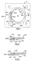
- the gasket A is a cylinder head gasket and includes a cylinder bore Hc, bolt holes Hb, water holes, oil holes and so on, as in the conventional gasket. In Fig. 1, however, the water holes and oil holes are omitted.
- the gasket A is formed of an upper first plate A10, and a lower second plate A11.
- the upper first plate A10 includes a base portion A10a extending substantially throughout the entire area of the gasket, a curved portion A10b extending from the base portion A10a, and a flange A10c extending from the curved portion A10b and located under the base portion A10a.
- the curved portion A10b define the cylinder bore Hc.
- the lower second plate A11 is situated under the base portion A10a, and has a hole A11a larger than the flange A10c and a bead A11b around the hole A11a.
- the bead A11b extends in the direction away from the upper first plate A10.
- the lower plate A11 further includes four curved dents A11c extending from a center of the hole A11a toward the bolt holes Hb.
- the size of the curved dent A11c extending along the periphery of the hole A11a is greater than the diameter of the bolt hole Hb.
- the gasket A further includes a ring plate A12 situated between the flange A10c and the base portion A10a.
- the ring plate A12 has generally an annular shape, and is formed of narrow portions A12a, and wide portions A12b alternately arranged to each other.
- the narrow portions A12a are located on the flange A10c, but the wide portions A12b extend beyond the flange A10c.
- the ring plate A12 When the gasket A is assembled, the ring plate A12 is sandwiched between the flange A10c and the base portion A10a.
- the lower plate A11 is disposed under the base portion of the upper plate A10 such that the wide portions A12b are disposed in the curved dents A11c. Accordingly, the wide portions A12b are located close to the bolt holes Hb without overlapping the lower plate A11.
- the ring plate A12 does not rotate relative to the upper and lower plates A10, A11.
- the ring plate A12 since the ring plate A12 has the wide portions A12b close to the bolt holes Hb, the tightening pressures applied from the bolts to the ring plate A12 are spread at the wide portions A12b, not small areas like the narrow portions. Accordingly, the tightening pressures are widely supported at the ring plate, and are not concentrated at small areas. Therefore, the tightening pressures by the bolts are properly spread or distributed on the ring plate A12 as a whole. Thus, the area around the cylinder bore Hc can be securely sealed.
- the ring plate A12 engages the lower plate A11 at the wide portions 12b, the ring plate A12 does not rotate relative to the upper and lower plates A10, A11. Thus, leakage due to rotation of the ring plate A12 is prevented.
- Figs. 4 and 5 show a second embodiment B of a metal laminate gasket of the invention.
- the gasket B is formed of an upper plate B10 with a curved portion B10b and a flange B10c, a lower plate B11 with a bead B11b, and a ring plate B12 with narrow and wide portions B12a, B12b, similar to the gasket A.
- the lower plate A11 includes the curved dents A11c near the bolt holes Hb, but in the gasket B, there is no curved dent in the lower plate B11.
- a hole B11a in the lower plate B11 has a circular shape. Therefore, when the gasket B is assembled, the wide portions B12b of the ring plate B12 are partly laminated or overlapped on the lower plate B11.
- the wide portions B12b are compressed.
- the ring plate B12 is made thin and the wide or overlapped portions are located away from the cylinder bore Hc, so that the thickness of the overlapped portions may be neglected. Dents may be formed in the engine parts above or below the overlapped portions to avoid the uneven thickness of the gasket B.
- the ring plate B12 does not move or rotate relative to the upper and lower plates B10, B11.
- the rest of the structure and operation of the gasket B are the same as explained in the gasket A.
- the ring plate installed in the gasket has the wide portions near the bolt holes to receive and support the tightening pressures applied from the bolts when the gasket is tightened.
- the tightening pressures can be evenly applied onto the ring plate to securely seal around the hole to be sealed.
- the wide portions need not be formed for all the portions near the bolt holes, and also, the size of the wide portion can be selected as desired based on the surface pressure applied thereto.
Landscapes
- Engineering & Computer Science (AREA)
- General Engineering & Computer Science (AREA)
- Mechanical Engineering (AREA)
- Gasket Seals (AREA)
Claims (7)
- Eine Mehrlagenmetalldichtung (A, B) für einen Motor mit innerer Verbrennung, wobei der Motor eine abzudichtende Öffnung (Hc) und um die Öffnung (Hc) herum angeordnete Bolzenöffnungen (Hb) aufweist, mit:einer ersten Metallplatte (A10, B10), die einen Basisabschnitt (A10a), der sich im Wesentlichen über einen gesamten Bereich der Dichtung (A, B) erstreckt, einen geschwungenen Abschnitt (A10b, B10b), der sich von dem Basisabschnitt (A10a) erstreckt, um eine erste Öffnung zu definieren, die der Öffnung (Hc) des Motors entspricht, einen Flansch (A10c, B10c), der sich von dem geschwungenen Abschnitt (A10b, B10b) erstreckt und unter dem Basisabschnitt (A10a) angeordnet ist, und zweite Öffnungen aufweist, die den Bolzenöffnungen (Hb) des Motors entsprechen,einer zweiten Metallplatte (A11, B11), die unter dem Basisabschnitt (A10a) angeordnet ist, wobei die zweite Metallplatte (A11, B11) eine dritte Öffnung (A11a, B11a), die größer als die erste Öffnung ist, so dass die zweite Metallplatte (A11, B11) den Flansch (A10c, B10c) nicht überlappt, und vierte Öffnungen aufweist, die unter der zweiten Öffnung angeordnet sind, undeinem Metallring (A12, B12), der zwischen dem Flansch (A10c, B10c) und dem Basisabschnitt (A10a) angeordnet ist, wobei die Mehrlagenmetalldichtung (A, B) dadurch gekennzeichnet ist, dass der Metallring (A12, B12) schmale Abschnitte (A12a, B12a) und weite Abschnitte (A12b, B12b) aufweist, die abwechselnd zueinander angeordnet sind, wobei die weiten Abschnitte (A12b, B12b) nahe zu den zweiten und vierten Öffnungen angeordnet sind, die den Bolzenöffnungen (Hb) entsprechen, so dass hohe Anzugsdrücke von den weiten Abschnitten (A12b, B12b) getragen werden, wenn die in den Bolzenöffnungen (Hb) angeordneten Bolzen angezogen werden.
- Eine Mehrlagenmetalldichtung (A, B) gemäß Anspruch 1, wobei jeder der schmalen Abschnitte (A12a, B12a) eine konstante und gleichförmige Weite besitzt und jeder der weiten Abschnitte (A12b, B12b) geschwungen ist, so dass er sich von einem Mittelpunkt des Metallrings (A12, B12) radial nach außen erstreckt.
- Eine Mehrlagenmetalldichtung (A, B) nach Anspruch 2, wobei der geschwungene Abschnitt (A12b, B12b) eine Länge zwischen zwei benachbarten schmalen Abschnitten (A12 B12a) aufweist, die größer als der Durchmesser der zweiten und vierten Öffnungen ist.
- Eine Mehrlagenmetalldichtung (A, B) nach einem der Ansprüche 1 bis 3, wobei die dritte Öffnung (A11a, B11a) eine Größe aufweist, die größer als ein äußerer Durchmesser der schmalen Abschnitte (A12a, B12a) des Metallrings (A12, B12) aufweist, so dass die schmalen Abschnitte (A12a, B12a) des Metallrings (A12, B12) wenigstens in der dritten Öffnung (A11a, B11a) der zweiten Metallplatte (A11, B11) angeordnet sind.
- Eine Mehrlagenmetalldichtung (A) nach Anspruch 4, wobei die zweite Metallplatte (A11) Vertiefungen (A11c) aufweist, die sich von einem Mittelpunkt der Öffnung (A11a) radial nach außen erstrecken, wobei die Vertiefungen (A11c) Formen aufweisen, die den weiten Abschnitten (A12b) des Metallrings (A12) entsprechen, so dass der Metallring (A12) vollständig in der dritten Öffnung (A11a) angeordnet ist.
- Eine Mehrlagenmetalldichtung (B) nach Anspruch 4, wobei die dritte Öffnung (B11a) eine Größe aufweist, die kleiner als ein äußerer Durchmesser der weiten Abschnitte (B12b) des Metallrings (B12) ist, so dass die zweite Metallplatte (B11) die weiten Abschnitte (B12b) überlappt.
- Eine Mehrlagenmetalldichtung (A,B) nach einem der Ansprüche 1 bis 6, wobei die zweite Metallplatte (A11, B11) eine Sicke (A11b, B11b) umfasst, die die dritte Öffnung (A11a, B11a) umgibt, um außerhalb des Flanschs (A10c, B10c) abzudichten.
Applications Claiming Priority (6)
| Application Number | Priority Date | Filing Date | Title |
|---|---|---|---|
| JP60467/97 | 1997-03-14 | ||
| JP6046797 | 1997-03-14 | ||
| JP9060467A JP2905754B2 (ja) | 1997-03-14 | 1997-03-14 | 金属積層形ガスケット |
| JP7782097 | 1997-03-28 | ||
| JP77820/97 | 1997-03-28 | ||
| JP9077820A JP2875230B2 (ja) | 1997-03-28 | 1997-03-28 | 金属積層形ガスケット |
Publications (3)
| Publication Number | Publication Date |
|---|---|
| EP0864785A2 EP0864785A2 (de) | 1998-09-16 |
| EP0864785A3 EP0864785A3 (de) | 1999-10-20 |
| EP0864785B1 true EP0864785B1 (de) | 2002-07-31 |
Family
ID=26401539
Family Applications (1)
| Application Number | Title | Priority Date | Filing Date |
|---|---|---|---|
| EP98103464A Expired - Lifetime EP0864785B1 (de) | 1997-03-14 | 1998-02-27 | Mehrlagenmetalldichtung mit unregelmässiger Dichtungsringgrösse |
Country Status (5)
| Country | Link |
|---|---|
| US (1) | US5957463A (de) |
| EP (1) | EP0864785B1 (de) |
| CN (1) | CN1077650C (de) |
| AU (1) | AU720084B2 (de) |
| DE (1) | DE69806829T2 (de) |
Families Citing this family (24)
| Publication number | Priority date | Publication date | Assignee | Title |
|---|---|---|---|---|
| US6139025A (en) * | 1997-07-17 | 2000-10-31 | Ishikawa Gasket Co., Ltd. | Metal laminate gasket with wide and narrow flange portions |
| US6036195A (en) * | 1998-03-09 | 2000-03-14 | Ishikawa Gasket Co., Ltd. | Metal gasket with double beads |
| JP3113642B2 (ja) * | 1999-02-01 | 2000-12-04 | 石川ガスケット株式会社 | 金属積層形ガスケット |
| JP2001012611A (ja) * | 1999-06-30 | 2001-01-16 | Nippon Gasket Co Ltd | 金属製ガスケット |
| JP3751786B2 (ja) * | 1999-12-27 | 2006-03-01 | 石川ガスケット株式会社 | 金属積層形ガスケット |
| JP2002122240A (ja) | 2000-10-11 | 2002-04-26 | Ishikawa Gasket Co Ltd | 金属積層形ガスケット |
| DE10117178B4 (de) * | 2001-04-05 | 2006-11-09 | Elringklinger Ag | Zylinderkopfdichtung |
| FR2824613B1 (fr) * | 2001-05-09 | 2003-07-25 | Meillor Sa | Joint metallique a insert fibreux |
| DE10143431B4 (de) * | 2001-09-05 | 2006-02-02 | Elringklinger Ag | Zylinderkopfdichtung |
| US7017918B2 (en) * | 2001-10-25 | 2006-03-28 | Federal-Mogul World Wide, Inc. | Combustion stopper seal |
| ES2369885T3 (es) | 2003-03-14 | 2011-12-07 | Renault S.A.S. | Disposiciones de junta de culata para conjuntos de motor. |
| JP3811700B2 (ja) | 2003-12-19 | 2006-08-23 | 石川ガスケット株式会社 | 金属積層形ガスケット |
| JP3864162B2 (ja) * | 2004-02-04 | 2006-12-27 | 石川ガスケット株式会社 | シリンダヘッドガスケット |
| JP4056503B2 (ja) * | 2004-07-23 | 2008-03-05 | 石川ガスケット株式会社 | 金属ガスケット |
| JP3949690B2 (ja) * | 2005-01-27 | 2007-07-25 | 石川ガスケット株式会社 | 金属積層形ガスケット |
| DE102005020923A1 (de) * | 2005-05-04 | 2006-11-16 | Federal-Mogul Sealing Systems Gmbh | Flachdichtung, insbesondere Zylinderkopfdichtung |
| KR100866369B1 (ko) * | 2006-05-16 | 2008-10-31 | 도요타지도샤가부시키가이샤 | 실린더 헤드 개스킷 |
| JP2008202625A (ja) * | 2007-02-16 | 2008-09-04 | Ishikawa Gasket Co Ltd | 積層型ガスケット |
| DE102007015690B3 (de) * | 2007-03-31 | 2008-05-08 | Federal-Mogul Sealing Systems Gmbh | Verfahren zur Herstellung einer lösbaren Klemmverbindung einzelner Lagen einer Flachdichtung und Lochstempel zur Durchführung des Verfahrens |
| JP4536765B2 (ja) * | 2007-10-12 | 2010-09-01 | 石川ガスケット株式会社 | 金属ガスケット |
| ES2579237T3 (es) * | 2010-11-09 | 2016-08-08 | General Electric Technology Gmbh | Disposición de cierre estanco |
| KR101909561B1 (ko) | 2011-03-03 | 2018-10-19 | 페더럴-모걸 엘엘씨 | 실린더 헤드 개스킷 |
| CN102168630A (zh) * | 2011-04-11 | 2011-08-31 | 合肥恒信汽车发动机部件制造有限公司 | 一种发动机密封环的固定结构 |
| CN107061734B (zh) * | 2016-12-29 | 2018-11-16 | 潍柴动力股份有限公司 | 一种用于法兰接合面的连接的垫片及其设计方法 |
Family Cites Families (13)
| Publication number | Priority date | Publication date | Assignee | Title |
|---|---|---|---|---|
| JPS62155375A (ja) * | 1985-12-27 | 1987-07-10 | Nippon Metal Gasket Kk | 金属ガスケツト |
| US4896891A (en) * | 1988-05-16 | 1990-01-30 | Ishikawa Gasket Co., Ltd. | Steel laminate gasket with associated beads |
| US4898396A (en) * | 1988-08-11 | 1990-02-06 | Ishikawa Gasket Co., Ltd. | Steel laminate gasket |
| JP2935545B2 (ja) * | 1990-07-16 | 1999-08-16 | 日本リークレス工業株式会社 | メタルガスケット |
| EP0468526B1 (de) * | 1990-07-26 | 1995-04-05 | Taiho Kogyo Co., Ltd. | Metalldichtung |
| JPH086805B2 (ja) * | 1992-06-09 | 1996-01-29 | 日本メタルガスケット株式会社 | 金属ガスケット |
| US5618049A (en) * | 1993-06-04 | 1997-04-08 | Japan Metal Gasket Co., Ltd. | Metallic gasket |
| JP3581162B2 (ja) * | 1993-07-07 | 2004-10-27 | 日本リークレス工業株式会社 | 金属ガスケットの製造方法 |
| JPH07253160A (ja) * | 1994-03-14 | 1995-10-03 | Nippon Riikuresu Kogyo Kk | メタルガスケット |
| BR9505567A (pt) * | 1995-04-26 | 1997-11-04 | Elringklinger Gmbh | Vedação metálica de cabeçote |
| DE19605871C2 (de) * | 1996-02-17 | 1998-01-29 | Elringklinger Gmbh | Metallische Zylinderkopfdichtung |
| JP2929485B2 (ja) * | 1996-05-22 | 1999-08-03 | 石川ガスケット株式会社 | 金属積層形ガスケット |
| JP2983465B2 (ja) * | 1996-05-22 | 1999-11-29 | 石川ガスケット株式会社 | 金属積層形ガスケット |
-
1998
- 1998-02-18 US US09/025,254 patent/US5957463A/en not_active Expired - Fee Related
- 1998-02-27 AU AU56397/98A patent/AU720084B2/en not_active Ceased
- 1998-02-27 DE DE69806829T patent/DE69806829T2/de not_active Expired - Fee Related
- 1998-02-27 EP EP98103464A patent/EP0864785B1/de not_active Expired - Lifetime
- 1998-03-13 CN CN98101106A patent/CN1077650C/zh not_active Expired - Fee Related
Also Published As
| Publication number | Publication date |
|---|---|
| CN1193689A (zh) | 1998-09-23 |
| EP0864785A3 (de) | 1999-10-20 |
| US5957463A (en) | 1999-09-28 |
| DE69806829T2 (de) | 2002-11-14 |
| AU5639798A (en) | 1998-09-17 |
| AU720084B2 (en) | 2000-05-25 |
| DE69806829D1 (de) | 2002-09-05 |
| EP0864785A2 (de) | 1998-09-16 |
| CN1077650C (zh) | 2002-01-09 |
Similar Documents
| Publication | Publication Date | Title |
|---|---|---|
| EP0864785B1 (de) | Mehrlagenmetalldichtung mit unregelmässiger Dichtungsringgrösse | |
| US5076595A (en) | Steel laminate gasket | |
| US5435575A (en) | Steel laminate gasket | |
| EP0500316B1 (de) | Metallaminatdichtung mit zwei Dichtungsringen | |
| US5511796A (en) | Metal laminate gasket with sealing shim | |
| KR0179041B1 (ko) | 넓은 밀봉면적을 가진 강박판 적층 개스킷 | |
| EP1387113B1 (de) | Metalldichtung mit einer Ringdichtung | |
| EP0892199B1 (de) | Mehrlagenmetalldichtung mit breiten und schmalen Flanschabschnitten | |
| US5131668A (en) | Steel laminate gasket with seal protecting member | |
| US5439234A (en) | Metal gasket with edge support beads | |
| EP0833086B1 (de) | Metallabdichtung mit Deckschicht | |
| US5306023A (en) | Cylinder head gasket with auxiliary sealing plate | |
| EP0518665B1 (de) | Mehrlagen-Metall-Dichtung mit Dichtungsöse | |
| US5961126A (en) | Metal gasket with peripheral bead | |
| US5368316A (en) | Metal laminate gasket with a plate connecting device | |
| US5199723A (en) | Steel laminate gasket with seal protecting member | |
| EP0431227B1 (de) | Stahllaminatdichtung | |
| US5899462A (en) | Metal laminate gasket with stepped sealing portion | |
| US5165372A (en) | Steel laminate type cylinder head gasket | |
| US5895055A (en) | Metal gasket with opposite flanges | |
| EP0713989B1 (de) | Metallische Laminatzylinderkopfdichtung mit einem hitzehemmenden Abschnitt | |
| US6056295A (en) | Metal laminate gasket | |
| EP0493954A1 (de) | Zylinderkopfdichtung aus Schichtstahl |
Legal Events
| Date | Code | Title | Description |
|---|---|---|---|
| PUAI | Public reference made under article 153(3) epc to a published international application that has entered the european phase |
Free format text: ORIGINAL CODE: 0009012 |
|
| AK | Designated contracting states |
Kind code of ref document: A2 Designated state(s): DE FR GB IT |
|
| AX | Request for extension of the european patent |
Free format text: AL;LT;LV;MK;RO;SI |
|
| PUAL | Search report despatched |
Free format text: ORIGINAL CODE: 0009013 |
|
| AK | Designated contracting states |
Kind code of ref document: A3 Designated state(s): AT BE CH DE DK ES FI FR GB GR IE IT LI LU MC NL PT SE |
|
| AX | Request for extension of the european patent |
Free format text: AL;LT;LV;MK;RO;SI |
|
| 17P | Request for examination filed |
Effective date: 19991020 |
|
| AKX | Designation fees paid |
Free format text: DE FR GB IT |
|
| 17Q | First examination report despatched |
Effective date: 20010410 |
|
| GRAG | Despatch of communication of intention to grant |
Free format text: ORIGINAL CODE: EPIDOS AGRA |
|
| GRAG | Despatch of communication of intention to grant |
Free format text: ORIGINAL CODE: EPIDOS AGRA |
|
| GRAH | Despatch of communication of intention to grant a patent |
Free format text: ORIGINAL CODE: EPIDOS IGRA |
|
| GRAH | Despatch of communication of intention to grant a patent |
Free format text: ORIGINAL CODE: EPIDOS IGRA |
|
| GRAA | (expected) grant |
Free format text: ORIGINAL CODE: 0009210 |
|
| AK | Designated contracting states |
Kind code of ref document: B1 Designated state(s): DE FR GB IT |
|
| REG | Reference to a national code |
Ref country code: GB Ref legal event code: FG4D |
|
| REF | Corresponds to: |
Ref document number: 69806829 Country of ref document: DE Date of ref document: 20020905 |
|
| ET | Fr: translation filed | ||
| PLBE | No opposition filed within time limit |
Free format text: ORIGINAL CODE: 0009261 |
|
| STAA | Information on the status of an ep patent application or granted ep patent |
Free format text: STATUS: NO OPPOSITION FILED WITHIN TIME LIMIT |
|
| 26N | No opposition filed |
Effective date: 20030506 |
|
| PGFP | Annual fee paid to national office [announced via postgrant information from national office to epo] |
Ref country code: FR Payment date: 20050208 Year of fee payment: 8 |
|
| PGFP | Annual fee paid to national office [announced via postgrant information from national office to epo] |
Ref country code: GB Payment date: 20050223 Year of fee payment: 8 |
|
| PG25 | Lapsed in a contracting state [announced via postgrant information from national office to epo] |
Ref country code: GB Free format text: LAPSE BECAUSE OF NON-PAYMENT OF DUE FEES Effective date: 20060227 |
|
| PGFP | Annual fee paid to national office [announced via postgrant information from national office to epo] |
Ref country code: IT Payment date: 20060228 Year of fee payment: 9 |
|
| GBPC | Gb: european patent ceased through non-payment of renewal fee |
Effective date: 20060227 |
|
| REG | Reference to a national code |
Ref country code: FR Ref legal event code: ST Effective date: 20061031 |
|
| PG25 | Lapsed in a contracting state [announced via postgrant information from national office to epo] |
Ref country code: FR Free format text: LAPSE BECAUSE OF NON-PAYMENT OF DUE FEES Effective date: 20060228 |
|
| PGFP | Annual fee paid to national office [announced via postgrant information from national office to epo] |
Ref country code: DE Payment date: 20090219 Year of fee payment: 12 |
|
| PG25 | Lapsed in a contracting state [announced via postgrant information from national office to epo] |
Ref country code: IT Free format text: LAPSE BECAUSE OF NON-PAYMENT OF DUE FEES Effective date: 20070227 |
|
| PG25 | Lapsed in a contracting state [announced via postgrant information from national office to epo] |
Ref country code: DE Free format text: LAPSE BECAUSE OF NON-PAYMENT OF DUE FEES Effective date: 20100901 |