EP0863721B1 - Electronic stethoscope with idealized bell and idealized diaphragm modes - Google Patents
Electronic stethoscope with idealized bell and idealized diaphragm modes Download PDFInfo
- Publication number
- EP0863721B1 EP0863721B1 EP96936853A EP96936853A EP0863721B1 EP 0863721 B1 EP0863721 B1 EP 0863721B1 EP 96936853 A EP96936853 A EP 96936853A EP 96936853 A EP96936853 A EP 96936853A EP 0863721 B1 EP0863721 B1 EP 0863721B1
- Authority
- EP
- European Patent Office
- Prior art keywords
- passband
- emphasized
- stethoscope
- sounds
- mode
- Prior art date
- Legal status (The legal status is an assumption and is not a legal conclusion. Google has not performed a legal analysis and makes no representation as to the accuracy of the status listed.)
- Expired - Lifetime
Links
- 230000001105 regulatory effect Effects 0.000 claims description 5
- 230000008447 perception Effects 0.000 claims 1
- 230000004044 response Effects 0.000 description 22
- 230000003321 amplification Effects 0.000 description 6
- 230000006870 function Effects 0.000 description 6
- 230000000873 masking effect Effects 0.000 description 6
- 238000003199 nucleic acid amplification method Methods 0.000 description 6
- 230000003595 spectral effect Effects 0.000 description 6
- 230000005540 biological transmission Effects 0.000 description 5
- 238000001514 detection method Methods 0.000 description 5
- 238000000926 separation method Methods 0.000 description 5
- 238000010586 diagram Methods 0.000 description 4
- 238000012546 transfer Methods 0.000 description 4
- 238000002555 auscultation Methods 0.000 description 3
- 238000006243 chemical reaction Methods 0.000 description 3
- 230000000694 effects Effects 0.000 description 3
- 210000003709 heart valve Anatomy 0.000 description 3
- 238000012545 processing Methods 0.000 description 3
- 230000009467 reduction Effects 0.000 description 3
- 238000011109 contamination Methods 0.000 description 2
- 238000003745 diagnosis Methods 0.000 description 2
- 230000007613 environmental effect Effects 0.000 description 2
- 210000003128 head Anatomy 0.000 description 2
- 230000036541 health Effects 0.000 description 2
- 238000002955 isolation Methods 0.000 description 2
- 230000007246 mechanism Effects 0.000 description 2
- 238000004321 preservation Methods 0.000 description 2
- 238000012216 screening Methods 0.000 description 2
- 230000000007 visual effect Effects 0.000 description 2
- 206010011906 Death Diseases 0.000 description 1
- 208000035211 Heart Murmurs Diseases 0.000 description 1
- 208000037656 Respiratory Sounds Diseases 0.000 description 1
- 206010044565 Tremor Diseases 0.000 description 1
- 230000002411 adverse Effects 0.000 description 1
- 230000032683 aging Effects 0.000 description 1
- 238000004458 analytical method Methods 0.000 description 1
- 239000003990 capacitor Substances 0.000 description 1
- 230000000747 cardiac effect Effects 0.000 description 1
- 230000008859 change Effects 0.000 description 1
- 238000010276 construction Methods 0.000 description 1
- 230000000994 depressogenic effect Effects 0.000 description 1
- 238000013461 design Methods 0.000 description 1
- 230000009977 dual effect Effects 0.000 description 1
- 210000000613 ear canal Anatomy 0.000 description 1
- 230000001605 fetal effect Effects 0.000 description 1
- 238000001914 filtration Methods 0.000 description 1
- 210000003811 finger Anatomy 0.000 description 1
- 238000010348 incorporation Methods 0.000 description 1
- 238000004519 manufacturing process Methods 0.000 description 1
- 230000000241 respiratory effect Effects 0.000 description 1
- 210000003813 thumb Anatomy 0.000 description 1
- 230000007306 turnover Effects 0.000 description 1
Images


Classifications
-
- A—HUMAN NECESSITIES
- A61—MEDICAL OR VETERINARY SCIENCE; HYGIENE
- A61B—DIAGNOSIS; SURGERY; IDENTIFICATION
- A61B7/00—Instruments for auscultation
- A61B7/02—Stethoscopes
- A61B7/04—Electric stethoscopes
Definitions
- Stethoscopes have long been used by physicians to monitor auscultatory sounds.
- stethoscopes have been comprised of a head or chestpiece, a sound transmission mechanism and an earpiece assembly.
- the chestpiece is adapted to be placed near or against the skin, body, of a patient for gathering the auscultatory sounds.
- the sound transmission mechanism transmits the gathered sound to an earpiece, or a pair of earpieces called a binaural earpiece, where the physician or other health professional may monitor the sound.
- stethoscopes have utilized electronics for at least part of the sound processing path.
- the auditory sound is picked up by a microphone usually located in a detection device which is similar to the chestpiece of a conventional acoustic stethoscope in external appearance.
- the electrical signal from the microphone is then processed electronically and is coupled to a speaker, or speakers, where the electrical signal is converted back into an auditory sound for reception by the physician.
- other electronic analysis or display of the auscultatory sound may be performed by the signal processor, in addition to the usual conversion back into an auditory sound.
- an electronic stethoscope allows for the provision of many desirable features, such as noise reduction, signal amplification, wider bandwidth, display of auscultatory sounds and selection of different frequency responses
- the electronic scope has not gained wide acceptance due to the impression that electronic stethoscopes sound "different” or “electronic” or in some way distort the sound.
- electronic stethoscopes sound "different” or “electronic” or in some way distort the sound.
- DE-A- 4 342 768 discloses a stethoscope.
- a frequency transfer function for a diaphragm mode is disclosed
- DE-U- 91 07 532 discloses a stethoscope with passband filters.
- the stethoscope includes selectable frequency ranges. There are no clamped or de-emphasized side bands.
- the present electronic stethoscope is designed to emulate the frequency response of a standard acoustical stethoscope in both bell and diaphragm modes, while providing additional features attainable only with an electronic stethoscope, such as signal amplification, noise reduction, wider bandwidth, and rapid mode selection.
- the electronic stethoscope includes an idealized diaphragm mode and an idealized bell mode.
- the idealized diaphragm mode and the idealized bell mode each include emphasized passbands that are spectrally separate.
- Each of the idealized diaphragm and idealized bell modes can also include a de-emphasized passband.
- the electronic stethoscope can also include a wideband mode. The wideband mode permits the user to hear high frequency sounds such as those associated with mechanical heart valves or some lung sounds.
- the spectral separation of the idealized bell and diaphragm modes allows the user to more easily hear and distinguish between different sounds of interest.
- the spectral separation of the emphasized frequencies reduces masking of high frequency sounds by low frequency sounds in the diaphragm mode, and reduces masking of low frequency sounds by high frequency sounds in the bell mode.
- Spectral separation with preservation of the de-emphasized frequencies of the idealized diaphragm and idealized bell modes allows the user to more easily hear, differentiate and identify different body sounds, and also gives the overall impression that the electronic stethoscope emulates the sound quality of a good acoustic stethoscope.
- Electronic stethoscopes should provide acoustic response at least equal to their conventional acoustic counterparts. Electronic stethoscopes should also be similar to the weight, feel and ease of use of their conventional acoustic counterparts. In order for the physician to gain the most advantageous use of the stethoscope, the stethoscope should provide the highest possible clarity of auscultatory sound from the patients body, as well as provide the greatest possible isolation from all extraneous sounds. In addition, electronic stethoscopes must offer sound isolation from the surroundings in which the stethoscope is used.
- Electronic stethoscope 10 illustrated in FIG. 1 consists of a chestpiece 12, or stethoscope head, a headset 14 and a connecting tube 16.
- the binaural assembly 14 has two eartips 18 and 20 adapted to fit in the ear of a user, typically a physician or other medical professional.
- Tubes 22 and 24 are acoustically coupled to eartips 18 and 20, respectively.
- the eartips 18 and 20 effectively seal in the ear canal of the user to exclude ambient noise.
- Enclosure 34 located at juncture of tubes 22 and 24 with connecting tube 16, provides a location for a speaker (not shown).
- the speaker transforms the auscultatory sounds which are picked up by chestpiece 12 and transduced into and processed in the electrical domain back to the acoustic domain where tubes 22 and 24 transmit the acoustic sounds to eartips 18 and 20, respectively.
- the preferred sound transmission system of stethoscope 10 is electronic.
- a simplified block diagram of the electronic sound transmission system 100 is illustrated in FIG. 2.
- the sound transmission system 100 includes at least one microphone 102 which acts as an acoustical transducer to receive auscultatory sounds from the body and transform the auscultatory sounds into an electrical signal.
- the stethoscope could include two or more microphones, although the system will be described with one microphone for purposes of illustration.
- This electrical signal is amplified and filtered by preamp/high pass filter 104.
- the preferred embodiment of the present electronic stethoscope is designed to emulate the frequency response of a standard acoustical stethoscope in both bell and diaphragm modes, while providing additional features attainable only with an electronic stethoscope, such as signal amplification, noise reduction, wider bandwidth, and mode selection.
- filters TF1 106, TF2 108 and TF3 110 permit selection between three different modes of operation of the electronic stethoscope. Additional filters and/or modes could be added without departing from the scope of the present invention.
- Emulation of the frequency response of a standard acoustical stethoscope is achieved with filters TF2 108 and TF3 110.
- Filter TF2 108 emulates the diaphragm mode of a standard acoustical stethoscope, while filter TF3 110 emulates the bell mode of a standard acoustical stethoscope.
- Filter TF1 106 provides a wideband frequency response which allows a user to hear a broad range of frequencies, including high frequency sounds such as those produced by mechanical heart valves and the like. These sounds can occur in a frequency range that is not audible with most acoustic stethoscopes.
- Power/mode switch 130 provides for both power on of the circuitry and for mode selection in a single switch.
- Mode indicators 134 provide visual indication to the user as to the current operational mode of the stethoscope.
- Switching logic 132 is connected to power/mode switch 130 and controls electronic switch 112 which in turn determines which filter is being used to form the output to the user.
- Power amplifier 114 receives the filtered signal and the signal is output to the user via speaker 116. It shall be understood that embodiments in which speaker 116 includes one, two or more speakers are within the scope of the present invention.
- the stethoscope 100 is powered by a battery system 124, which is preferably a commonly available AAA battery, preferably alkaline.
- a low battery detection/shutdown circuit 126 monitors available battery power and indicates when the battery power is running low via low battery indicator 128. When the voltage on the battery is below a predetermined level (1 volt, for example) the low battery detection/shutdown circuit 126 removes power from the stethoscope.
- an automatic shut down circuit 118 automatically removes power from the stethoscope after it has not been used for a preselected period of time.
- the automatic shutdown circuit removes power a preselected period of time after the stethoscope is powered on.
- the automatic shutdown circuit removes power a preselected period of time after the last time the mode changed.
- a voltage regulator 122 provides DC-DC conversion from the battery voltage to a higher voltage (preferably 3.0 volts) and regulates and filters the voltage provided to the stethoscope circuitry.
- Figures 3A, 3B and 3C show the preferred frequency responses of the filters TF1 106, TF2 108 and TF3 110, respectively.
- the filters TF2 108 and TF3 110 provide an idealized diaphragm mode and an idealized bell mode, respectively.
- Filter TF1 106 provides an additional wideband mode.
- the frequency response of idealized bell filter TF3 110 is shown in Figure 3C.
- the frequency responses of the filters TF2 108 and TF3 110 are preferably spectrally separate.
- the frequency response of filter TF1 106 is shown in Figure 3A, and provides a wideband frequency response.
- the wideband mode passes body sounds and other high frequency sounds within a wide spectral band.
- the idealized bell and diaphragm modes should cover the ranges of frequencies of the biological sounds of interest.
- the frequency content of the cardiac, respiratory, fetal, Korotkoff's sounds, and other biological sounds of interest are present in an overall frequency range of about 20-2000 Hz.
- the idealized bell and diaphragm modes each emphasize a different portion of this overall frequency range.
- the idealized diaphragm and idealized bell modes each have an overall passband which includes an emphasized passband and a de-emphasized passband.
- the preferred emphasized passband is in the range of about 200-500 Hz, while the preferred de-emphasized passband is in the range of about 20-200 Hz.
- the preferred emphasized passband is in the range of about 20-100 Hz, while the preferred de-emphasized passband is in the range about of 100-500 Hz.
- the relative amplitude of the emphasized passband is preferably greater than that of the de-emphasized passband.
- the idealized diaphragm mode emphasizes the high-frequency sounds while . preserving some of the low-frequency sounds. In this way, the idealized diaphragm mode minimizes masking of high-frequency sounds (such as cardiac murmurs) by low-frequency sounds. As shown in Figure 3B, the frequencies in the range of about 200-500 Hz are emphasized and the frequencies in the range of about 20-200 Hz are preserved but reduced in amplitude.
- the relative amplitude of the emphasized passband is sufficiently greater than that of the de-emphasized passband such that the resulting difference is perceptible to a user, and the attenuation of the de-emphasized passband is small enough such that the user can still hear the de-emphasized frequencies.
- a relative amplitude of the emphasized passband is in the range of about 5-15 dB greater than the de-emphasized passband is appropriate, with a preferred relative amplitude of about 10 dB.
- the idealized bell mode emphasizes the low-frequency sounds while preserving some of the high-frequency sounds.
- the idealized bell mode supports medical auscultation needs by minimizing psychoacoustic "masking" of low-frequency sounds by other sounds present at higher frequencies.
- the frequencies in the range of about 20-100 Hz are emphasized, while the frequencies in the range of about 100-500 Hz are preserved but reduced in amplitude.
- the relative amplitude of the emphasized passband is sufficiently greater than that of the de-emphasized passband such that the resulting difference is perceptible to a user, and the attenuation of the de-emphasized passband is small enough such that the user can still hear the de-emphasized frequencies.
- a relative amplitude of the emphasized passband is in the range of about 5-15 dB greater than the de-emphasized passband is appropriate, with a preferred relative amplitude of about 10 dB.
- Attenuation in the range of about 500-1000 Hz is about 12 dB/octave, and is about 18 dB/octave above 1000 Hz. Because the human ear is more sensitive at higher frequencies, the user can still hear sounds present at frequencies above 500 Hz in both the idealized bell and idealized diaphragm modes even though they have relatively greater attenuation. To eliminate contamination of the body sounds by other environmental sounds, such as low frequency hand tremor, external noise and electronic noise, the overall passband is restricted to about 20-1000 Hz in the idealized bell and idealized diaphragm modes, and about 20-2000 Hz in the wideband mode.
- the "cross-over" frequency of the idealized bell and idealized diaphragm frequency responses is in the range of about 100-200 Hz.
- a uniform, relative attenuation of 6-12 dB/octave in this range is preferred to suppress masking of diagnostically significant sounds by other simultaneous and spectrally-adjacent sounds.
- the emphasized and de-emphasized passbands in the idealized diaphragm and idealized bell modes result in an electronic stethoscope in which the idealized bell and idealized diaphragm modes are spectrally separate.
- the spectral separation of the idealized bell and diaphragm modes allows the user to more easily hear and distinguish between different sounds of interest.
- the spectral separation of the emphasized frequencies with preservation of the de-emphasized frequencies of the idealized diaphragm and idealized bell modes permits the electronic stethoscope to give the overall impression that it preserves the sound quality of a good acoustic stethoscope, which generally are not narrow-band instruments.
- Reduced masking of the high or low frequency sounds provided by the idealized diaphragm and idealized bell modes, respectively, means better clarity for the sound of interest, leading to more effective screening and diagnosis.
- the wideband mode of Figure 3A preferably provides a wider sound band with similar gain across all frequencies in the passband, but with a slight (e.g., 3-5 dB)de-emphasis below 100 Hz.
- the wideband mode provides a response that cannot be achieved in a traditional acoustic stethoscope, and thus allows the user to hear sounds, such as some high frequency sounds from artificial heart valves and the like, which cannot be heard with traditional acoustic stethoscopes.
- auscultation can begin in the wideband mode, with the ideal bell or diaphragm mode selected as the user determines the frequency range of most interest.
- the wideband mode may be preferred for use with an external computer-based data acquisition and display system.
- a data acquisition system permits software selection of different frequency responses and the ability to display and manipulate these different responses. Audio playback and manipulation is also possible
- the wideband mode may be preferred for this use because it passes a wider bandwidth. It shall be understood, however, that a data acquisition system, display, audio playback, etc., can be used with any of the idealized diaphragm, idealized bell, and wideband modes.
- the above described operational modes provide the physician with distinctly different and advantageous sound processing modes.
- the idealized bell and diaphragm modes are more spectrally separate than with traditional stethoscopes, allowing the user to more easily hear and distinguish different sounds of interest.
- Traditional acoustic stethoscopes typically lack a uniform relative attenuation outside of the bell/diaphragm cross-over band, due the presence of acoustic resonances.
- the switch over between bell and diaphragm modes with traditional acoustic stethoscopes generally required gross hand movements to engage a pneumatic valve or to turn over the chestpiece.
- the different transfer functions of this invention can be quickly selected with the simple and easily operable power/mode switch 130.
- the wideband mode allows the user to hear a full presentation of body sounds, and is also desirable for use with a computerized data acquisition and display system, or with an amplifier and speaker system, for example.
- filtering of the body sounds is performed electronically, the manufacturing process is much more precise and repeatable than earlier nonelectronic constructions.
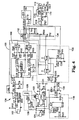
- FIG 4 shows a more detailed electrical schematic diagram of the electronic stethoscope.
- Electrical auscultatory sounds are received from the microphone 102 and are input into preamp/high pass filter 104, which consists of one section of operational amplifier IC3 and associated circuit components.
- the signal is then input into each of the filters TF1 106, TF2 108 and TF3 110.
- Capacitor C4 may be used to adjust the low frequency response of filter TF1 106, if desired.
- the filters can be realized with digital filters (ex. finite impulse response (FIR) filters), with digital signal processing (DSP) based filters, or with analog filter sections.
- FIR finite impulse response
- DSP digital signal processing
- filters TF2 108 and TF3 110 are both preferably implemented using second-order unity gain analog filters, and the signal from the second-order sections are combined by analog summing resistors (R37 and R41 for TF2 108, and R3 and R1 for TF3 110).
- Second-order unity gain analog filters are a particularly simple and cost-effective way to implement the desired transfer functions. Such unity-gain sections give very sharp cutoffs and also prevent unwanted "gain buildup" within long chains of filter elements, thereby reducing the likelihood of nonlinear saturation effects and distortion.
- the second-order filters minimize the presence of unwanted environmental noise (ex. voice, air-conditioner noise, etc.).
- Previously-used low-order filters typically having only a single pole) were ineffective in eliminating "ambient noise" contamination. Also, previous filter circuits were aimed at achieving simple low-pass or high-pass effects, not the shaped transfer functions of this invention.
- the overall frequency response of the stethoscope is also affected by other components such as the microphone, speaker, tubing, etc.
- resistors Rl, R3, R37 and R41 can be adjusted to compensate for variations caused by these other components. This adjustment results in an overall frequency response that closely approximates that of the filters.
- Electronic switch 112 determines which of the three filter outputs are passed on to power amplifier 114.
- Electronic switch 112 is preferably implemented using a quad analog switch part number 74LV4066D available from Philips Corporation.
- Electronic switch 112 is controlled by sequential switching circuitry 132 which is in turn controlled by power/mode switch 130.
- Power-mode switch 130 is preferably a single push-button switch which, in combination with switching circuitry 132, allows the user to both power on the stethoscope, make mode selections, and manually turn off the stethoscope.
- Switching circuitry 132 which preferably includes dual D flip-flops IC8, transistors Q2 and Q3 and associated circuit components, tracks the depressions of power/mode switch 130 an provides appropriate sequential control to switch 112.
- Mode indicators 134 are preferably three high efficiency LEDs and associated circuit components each of which indicates one of the three possible operational modes, broadband, diaphragm or bell, as provided by the respective filter circuits TF1 106, TF2 108 or TF3 110, respectively.
- Power amplifier 114 is a low power audio amplifier which provides differential speaker outputs to the speaker 116.
- the power amplifier is preferably implemented using part number MC34119, "Low Power Audio Amplifier", available from Motorola Corporation.
- the circuit is preferably powered using a single, commonly available AAA battery 124.
- Voltage regulator 122 provides DC-DC conversion of the power from the battery and also filters and regulates the voltage supplied to the circuit.
- voltage regulator 122 is an integrated circuit implemented using part number ML4890, "High Efficiency Low Ripple Boost Regulator", available from MicroLinear Corporation.
- Voltage regulator 122 can operate over a wide range of voltage (energy) from the AAA battery, as low as 1.0 volts and possibly as low as 0.8 volts or a wide range of power availability caused by quality or shelf aging of the battery.
- the voltage regulator 122 supplies a constant voltage to the stethoscope such that sound quality and gain are not affected by the battery condition or voltage. Thus the instrument will perform effectively deep into the end-of-life of the battery power source.
- Voltage regulator 122 further functions as a buffer and filter which isolates switching noise and ripple noise emanating from the DC-DC converter, the battery, or the battery connection system and other noise that would adversely affect sound quality of the instrument.
- voltage regulator 122 is implemented using a DC-DC step-up converter in series with a linear regulator.
- the DC-DC converter drives the linear regulator to reduce switching noise and ripple noise on the regulated output.
- This implementation effectively reduces the output noise of the voltage regulator 122 to 5 mV.
- the linear regulator thus supplies a constant, filtered voltage to the stethoscope such that sound quality and gain are not affected by battery condition or voltage.
- Variable resistor R19 allows the user to adjust the volume of the resulting body sounds as heard through the stethoscope.
- the middle range provided by variable resistor R19 is about unity gain (i.e., no amplification or attenuation of the incoming signal as compared to an acoustic stethoscope).
- This allows the electronic stethoscope to emulate the performance of an acoustic scope in that, in at least one volume setting, the output level is about equal to that of a traditional acoustic stethoscope.
- the variable resistor R19 allows enhancement (amplification) or quieting (attenuation) of the amplitude and thus the volume of the signal output of speaker 116.
- Low battery detection/shutoff circuit 126 is preferably implemented using a 1.15 volt voltage detector, part number S-8051ANR-NB, available from Seiko Corporation, which in combination with associated circuit components monitors the power output of the battery 124. When low power levels are detected (e.g., less than 1.15 volts in the preferred embodiment) the low battery indicator 128 is illuminated to inform the user that battery power is low and that the battery should soon be replaced. In an alternate embodiment, low battery detection/shutdown circuit 126 causes power to be removed from the stethoscope when the battery voltage is less than 1.0 volts.
- Automatic shut down circuit 118 automatically removes power from the stethoscope after it has not been used for a preselected period of time.
- Counter IC7 is connected through transistor Q1 to power/mode switch 130. Each time the stethoscope is powered on, counter IC7 is reset, and begins to count up to a number equivalent to a preselected period of time. In an alternate embodiment, each time the power/mode switch 130 is depressed, counter IC7 is reset, and begins to count up to a number equivalent to a preselected period of time. In the preferred embodiment, the preselected period of time is about 3 minutes. To provide for the preferred preselected period of time, the counter output Q13 is connected through Q1 to the shutdown pin on voltage regulator 122. Once the counter counts up, the output Q13 goes high, thus causing voltage regulator 122 to shut down which removes power from the circuit.
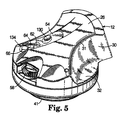
- FIG. 5 shows the preferred stethoscope chestpiece 12.
- Chestpiece 12 preferably includes a raised center portion 26, indented gripping surfaces 28 and 30 which, in combination with protruding edges 28 and 31 and surface 32 form the indented impressions with which the user can securely, easily, and comfortably grasp the chestpiece using the thumb and one or more fingers.
- the preferred stethoscope chestpiece 12 is more completely described in copending and commonly assigned U.S. Patent No. 5,663,532, filed on even date herewith, and entitled “ERGONOMETRIC STETHOSCOPE CHESTPIECE", which is incorporated herein by reference.
- the chestpiece 12 includes power/mode switch 130 and rotary control 58 for adjustment of the volume of the stethoscope as described above.
- Mode indicators 134 are preferably LEDs 62, 64, and 66. Alternatively, the mode indicator 134 is a small LCD or other type of display screen to further reduce power consumption.
- Each LED 62, 64 and 66 is associated with a different one of the preferred three operational modes, idealized diaphragm, idealized bell, and wideband.
- the LED 62, 64 or 66 associated with the current operational mode of the stethoscope is illuminated to provide visual indication to the user regarding the current operational mode of the stethoscope.
Landscapes
- Physics & Mathematics (AREA)
- Acoustics & Sound (AREA)
- Health & Medical Sciences (AREA)
- Life Sciences & Earth Sciences (AREA)
- Molecular Biology (AREA)
- Biomedical Technology (AREA)
- Heart & Thoracic Surgery (AREA)
- Medical Informatics (AREA)
- Engineering & Computer Science (AREA)
- Surgery (AREA)
- Animal Behavior & Ethology (AREA)
- General Health & Medical Sciences (AREA)
- Public Health (AREA)
- Veterinary Medicine (AREA)
- Details Of Audible-Bandwidth Transducers (AREA)
- Soundproofing, Sound Blocking, And Sound Damping (AREA)
- Headphones And Earphones (AREA)
Applications Claiming Priority (3)
| Application Number | Priority Date | Filing Date | Title |
|---|---|---|---|
| US563186 | 1995-11-27 | ||
| US08/563,186 US6026170A (en) | 1995-11-27 | 1995-11-27 | Electronic stethoscope with idealized bell and idealized diaphragm modes |
| PCT/US1996/016936 WO1997019640A1 (en) | 1995-11-27 | 1996-10-22 | Electronic stethoscope with idealized bell and idealized diaphragm modes |
Publications (2)
| Publication Number | Publication Date |
|---|---|
| EP0863721A1 EP0863721A1 (en) | 1998-09-16 |
| EP0863721B1 true EP0863721B1 (en) | 2000-04-12 |
Family
ID=24249461
Family Applications (1)
| Application Number | Title | Priority Date | Filing Date |
|---|---|---|---|
| EP96936853A Expired - Lifetime EP0863721B1 (en) | 1995-11-27 | 1996-10-22 | Electronic stethoscope with idealized bell and idealized diaphragm modes |
Country Status (8)
| Country | Link |
|---|---|
| US (1) | US6026170A (enExample) |
| EP (1) | EP0863721B1 (enExample) |
| JP (1) | JP4035635B2 (enExample) |
| AU (1) | AU710295B2 (enExample) |
| CA (1) | CA2236961C (enExample) |
| DE (1) | DE69607765T2 (enExample) |
| DK (1) | DK0863721T3 (enExample) |
| WO (1) | WO1997019640A1 (enExample) |
Families Citing this family (32)
| Publication number | Priority date | Publication date | Assignee | Title |
|---|---|---|---|---|
| US7006638B1 (en) * | 1994-08-30 | 2006-02-28 | Bang & Olufsen Technology A/S | Electronic stethoscope |
| NO300250B1 (no) * | 1995-02-09 | 1997-04-28 | Meditron As | Apparat for å lytte på kroppslyd |
| NO304870B1 (no) * | 1995-11-16 | 1999-02-22 | Meditron As | Lyttehode for elektronisk stetoskop |
| FR2767468B1 (fr) * | 1997-09-18 | 1999-10-22 | Jean Louis Burdeau | Stethoscope electronique |
| USD445184S1 (en) | 1998-02-25 | 2001-07-17 | Meditron As | Electronic stethoscope |
| US7130429B1 (en) * | 1998-04-08 | 2006-10-31 | Bang & Olufsen Technology A/S | Method and an apparatus for processing auscultation signals |
| US6878117B1 (en) | 1999-09-29 | 2005-04-12 | Zargis Medical Corp. | Handheld sensor for acoustic data acquisition |
| CA2382786A1 (en) * | 2001-04-30 | 2002-10-30 | The Government Of The United States Of America, As Represented By The Se Cretary, Department Of Health And Human Services, Centers For Disease Co | Auscultatory training system |
| US6691821B2 (en) | 2001-09-07 | 2004-02-17 | 3M Innovative Properties Company | Customizable spilt stem stethoscope and a method for providing same |
| KR20030065228A (ko) * | 2002-01-31 | 2003-08-06 | 김종수 | 청진음향신호를 표시하는 출력시스템 |
| US6810125B2 (en) * | 2002-02-04 | 2004-10-26 | Sabine, Inc. | Microphone emulation |
| USD477874S1 (en) | 2002-06-21 | 2003-07-29 | George Sommerfeld | Electronic stethoscope |
| USD477405S1 (en) | 2002-06-21 | 2003-07-15 | George Sommerfeld | Electronic stethoscope chestpiece |
| US20040037429A1 (en) * | 2002-08-23 | 2004-02-26 | Candioty Victor A. | Stethoscope |
| US20040096069A1 (en) * | 2002-11-14 | 2004-05-20 | Jen-Chien Chien | Electronic stethoscope |
| US8920343B2 (en) | 2006-03-23 | 2014-12-30 | Michael Edward Sabatino | Apparatus for acquiring and processing of physiological auditory signals |
| JP2008049111A (ja) * | 2006-07-27 | 2008-03-06 | Kiyoto Torisawa | 補聴機能付聴診器 |
| US7991165B2 (en) * | 2006-10-04 | 2011-08-02 | The United States Of America As Represented By The Secretary Of The Navy | Noise rejecting electronic stethoscope |
| USD639427S1 (en) * | 2010-10-26 | 2011-06-07 | Boyd Stacy L | Stethoscope tubing |
| USD724206S1 (en) * | 2013-05-19 | 2015-03-10 | MDF Instruments USA, Inc. | Combination tube and headset of a stethoscope |
| AU2015333646B2 (en) * | 2014-10-14 | 2018-08-09 | Arsil Nayyar Hussain | Systems, devices, and methods for capturing and outputting data regarding a bodily characteristic |
| CN106539595B (zh) * | 2016-12-20 | 2022-07-26 | 华南理工大学 | 一种提升肠鸣音区分度的主动多点肠蠕动监测装置 |
| USD908237S1 (en) * | 2017-01-16 | 2021-01-19 | Koninklijke Philips N.V. | Fetal and maternal monitor |
| WO2018211698A1 (ja) * | 2017-05-19 | 2018-11-22 | ヤマハ株式会社 | 音響処理装置および音響処理装置の制御方法 |
| EP3684259B1 (en) | 2017-09-19 | 2025-04-02 | Solventum Intellectual Properties Company | Ergonomic chestpiece |
| USD858759S1 (en) | 2017-09-19 | 2019-09-03 | 3M Innovative Properties Company | Stethoscope chestpiece |
| WO2020142278A1 (en) * | 2018-12-31 | 2020-07-09 | Star Luminal LLC | Electronic stethoscope with accessories |
| JP1688058S (enExample) * | 2020-08-24 | 2021-06-21 | ||
| EP4299009A1 (en) * | 2021-02-26 | 2024-01-03 | FUJIFILM Corporation | Electronic stethoscope |
| USD1030112S1 (en) | 2021-06-15 | 2024-06-04 | Star Luminal LLC | Portable light |
| USD1065529S1 (en) * | 2023-04-26 | 2025-03-04 | Eko Health, Inc. | Earpiece |
| WO2026015036A1 (es) * | 2024-07-10 | 2026-01-15 | Asociación Civil Universidad De Ciencias Y Humanidades | Estetoscopio electrónico ergonómico con pantalla de visualización de datos para diagnósticos |
Family Cites Families (70)
| Publication number | Priority date | Publication date | Assignee | Title |
|---|---|---|---|---|
| US2001537A (en) * | 1935-05-14 | Stethoscope | ||
| US1658327A (en) * | 1928-02-07 | obi new yobk | ||
| US3182129A (en) * | 1965-05-04 | Clark etal electronic stethoscope | ||
| US2340714A (en) * | 1941-01-04 | 1944-02-01 | Socony Vacuum Oil Co Inc | Method and apparatus for sound analysis |
| US2699465A (en) * | 1952-10-16 | 1955-01-11 | Hamilton Selden | Device for indicating the cessation of cardiac function |
| US3087016A (en) * | 1960-11-16 | 1963-04-23 | Joseph D Dahl | Stethoscopic device |
| US3311703A (en) * | 1963-05-21 | 1967-03-28 | Carl E Grinstead | Microphone with low frequency filter |
| US3247324A (en) * | 1964-06-26 | 1966-04-19 | Cefaly | Acoustic and electronic stethoscope |
| US3455293A (en) * | 1964-08-05 | 1969-07-15 | Robert W M Bethune | Stethoscope device |
| US3525810A (en) * | 1966-12-05 | 1970-08-25 | Itek Corp | Microphone assembly for use in a stethoscope |
| US3555187A (en) * | 1966-12-19 | 1971-01-12 | Donald G Rowley | Stethoscope |
| US3539724A (en) * | 1967-07-03 | 1970-11-10 | Daniel C Keesee | Combination electronic and air-column actuated stethoscope |
| US3651798A (en) * | 1970-05-15 | 1972-03-28 | Parke Davis & Co | Blood pressure indicator and noise |
| US3772478A (en) * | 1971-12-27 | 1973-11-13 | Instrument Systems Corp | Stethoscope headset |
| US3790712A (en) * | 1972-02-24 | 1974-02-05 | Computer Medical Science Corp | Electronic stethoscope system |
| US3846585A (en) * | 1972-09-21 | 1974-11-05 | Plastics Dev Corp Of America | Recording stethoscope |
| US3858005A (en) * | 1973-11-15 | 1974-12-31 | Marshall R | Stethoscope with display |
| US3989895A (en) * | 1974-05-08 | 1976-11-02 | Daniel Sr Philip S O | Stethoscope transducer |
| US4071694A (en) * | 1976-08-31 | 1978-01-31 | Minnesota Mining And Manufacturing Company | Stethoscope |
| US4072822A (en) * | 1976-09-27 | 1978-02-07 | Yoshihito Yamada | Two-way stethoscope for direct and amplified sound |
| US4170717A (en) * | 1977-02-18 | 1979-10-09 | Walshe James C | Electronic stethoscope |
| FR2405060A1 (fr) * | 1977-10-10 | 1979-05-04 | Attenburrow Donald Percy | Stethoscope |
| US4220160A (en) * | 1978-07-05 | 1980-09-02 | Clinical Systems Associates, Inc. | Method and apparatus for discrimination and detection of heart sounds |
| US4254302A (en) * | 1979-06-05 | 1981-03-03 | Walshe James C | Electronic stethoscope |
| JPS5627246A (en) * | 1979-08-09 | 1981-03-17 | Dentaru Electronics Kenkyusho | Dental stethoscope |
| JPS5742214A (en) * | 1980-08-27 | 1982-03-09 | Sony Corp | Power amplifier |
| US4424815A (en) * | 1980-10-14 | 1984-01-10 | Kuntz David H | Stethoscope-type recording system with stretched-in-time playback |
| US4377727A (en) * | 1980-12-24 | 1983-03-22 | Schwalbach Joseph C | Stethoscope having means for measuring pulse frequency |
| US4401125A (en) * | 1981-09-21 | 1983-08-30 | The Kendall Company | Stethoscope securing pad |
| DE3143372C2 (de) * | 1981-11-02 | 1985-10-17 | Robert Bosch Gmbh, 7000 Stuttgart | Verfahren zum elektronischen Auswerten der bei der Blutdruckmessung nach der Methode Riva-Rocci auftretenden Korotkoff-Geräusche |
| US4438772A (en) * | 1982-04-08 | 1984-03-27 | Intech Systems Corp. | Differential stethoscope |
| US4534058A (en) * | 1983-03-29 | 1985-08-06 | The Hart Group | Electronic stethoscope with automatic power shut-off |
| US4618986A (en) * | 1983-03-29 | 1986-10-21 | The Hart Group | Electronic stethoscope |
| US4498188A (en) * | 1983-05-04 | 1985-02-05 | Stanton Magnetics, Inc. | Electronic stethoscope for monitoring the operation of a prosthetic valve implanted in a patient's heart |
| CA1206216A (en) * | 1984-01-24 | 1986-06-17 | Russell W. Brown | Audio amplifier output stage |
| SE452946B (sv) * | 1984-01-30 | 1988-01-04 | Karolinska Inst | Anordning for overvakning av andningen hos spedbarn |
| US4528690A (en) * | 1984-03-12 | 1985-07-09 | Genovation, Inc. | Compact hybrid stethoscope |
| US4598417A (en) * | 1984-08-15 | 1986-07-01 | Research Corporation | Electronic stethoscope |
| US4607643A (en) * | 1984-11-09 | 1986-08-26 | Bell Floyd R | Endotracheal tube/stethoscope combination |
| US4594731A (en) * | 1984-11-09 | 1986-06-10 | University Of Utah | Electronic stethoscope |
| US4917107A (en) * | 1984-11-09 | 1990-04-17 | Medi-Tube Corporation | Endotracheal tube/stethoscope combination |
| JPS61161790A (ja) * | 1985-01-11 | 1986-07-22 | 富士電気化学株式会社 | コイルを含む電子回路モジユ−ル |
| US4672975A (en) * | 1985-06-17 | 1987-06-16 | Vladimir Sirota | Stethoscope with image of periodically expanding and contracting heart |
| US4720866A (en) * | 1985-09-20 | 1988-01-19 | Seaboard Digital Systems, Inc. | Computerized stethoscopic analysis system and method |
| CH665112A5 (fr) * | 1985-10-11 | 1988-04-29 | Eric Furugard | Stethoscope acoustique et a filtre electrique. |
| US4649928A (en) * | 1985-10-21 | 1987-03-17 | Gms Engineering Corporation | Noise-immune blood pressure measurement technique and system |
| US4792145A (en) * | 1985-11-05 | 1988-12-20 | Sound Enhancement Systems, Inc. | Electronic stethoscope system and method |
| US4731849A (en) * | 1986-07-30 | 1988-03-15 | Bloomfield Iii John W | Electronic ausculscope |
| US4783814A (en) * | 1986-10-09 | 1988-11-08 | Comprehensive Health Care Corp. Of America | Stethoscope having pseudostereophonic binaural enhancement |
| US4783813A (en) * | 1986-12-24 | 1988-11-08 | Lola R. Thompson | Electronic sound amplifier stethoscope with visual heart beat and blood flow indicator |
| SE8702160L (sv) * | 1987-05-25 | 1988-11-26 | Hoek Instr Ab | Stetoskop foer anvaendning vid magnetresonansdiagnostik m m |
| US5010889A (en) * | 1988-02-04 | 1991-04-30 | Bloodline Technology | Intelligent stethoscope |
| US4991581A (en) * | 1988-03-04 | 1991-02-12 | Andries Tek R&D Limited Partnership | Acoustic processing apparatus |
| US4985925A (en) * | 1988-06-24 | 1991-01-15 | Sensor Electronics, Inc. | Active noise reduction system |
| US4972841A (en) * | 1988-11-14 | 1990-11-27 | Iguchi Robert K | Stethoscope with pulse rate display |
| JPH02118322U (enExample) * | 1989-03-08 | 1990-09-21 | ||
| US5036543A (en) * | 1989-06-30 | 1991-07-30 | Pioneer Electronic Corporation | Noise suppression apparatus for FM receiver |
| US5003605A (en) * | 1989-08-14 | 1991-03-26 | Cardiodyne, Inc. | Electronically augmented stethoscope with timing sound |
| US5025809A (en) * | 1989-11-28 | 1991-06-25 | Cardionics, Inc. | Recording, digital stethoscope for identifying PCG signatures |
| DE4100607A1 (de) * | 1991-01-11 | 1992-07-16 | Gert Wiedemann Fa | Stethoskop |
| DE9107532U1 (de) * | 1991-06-19 | 1992-05-07 | Klügl, Günter, 8000 München | Elektronisches Stethoskop |
| ES2119150T3 (es) * | 1992-12-07 | 1998-10-01 | Andromed Inc | Estetoscopio electronico. |
| US5347583A (en) * | 1992-12-16 | 1994-09-13 | Minnesota Mining And Manufacturing Company | Electronic stethoscope having binaural earpiece |
| US5367575A (en) * | 1992-12-16 | 1994-11-22 | Minnesota Mining And Manufacturing Company | Electronic stethoscope having battery carriage |
| US5492129A (en) * | 1993-12-03 | 1996-02-20 | Greenberger; Hal | Noise-reducing stethoscope |
| USD361840S (en) | 1994-04-21 | 1995-08-29 | Gary Savage | Stethoscope head |
| USD362063S (en) | 1994-04-21 | 1995-09-05 | Gary Savage | Stethoscope headset |
| US5550902A (en) * | 1994-08-17 | 1996-08-27 | American Telecare, Inc. | Remote stethoscope signal processing system |
| ES2264129T3 (es) * | 1994-08-30 | 2006-12-16 | BANG & OLUFSEN MEDICOM A/S | Estetoscopio electronico. |
| US5467775A (en) * | 1995-03-17 | 1995-11-21 | University Research Engineers & Associates | Modular auscultation sensor and telemetry system |
-
1995
- 1995-11-27 US US08/563,186 patent/US6026170A/en not_active Expired - Lifetime
-
1996
- 1996-10-22 DK DK96936853T patent/DK0863721T3/da active
- 1996-10-22 EP EP96936853A patent/EP0863721B1/en not_active Expired - Lifetime
- 1996-10-22 AU AU74673/96A patent/AU710295B2/en not_active Ceased
- 1996-10-22 JP JP52046997A patent/JP4035635B2/ja not_active Expired - Fee Related
- 1996-10-22 WO PCT/US1996/016936 patent/WO1997019640A1/en not_active Ceased
- 1996-10-22 DE DE69607765T patent/DE69607765T2/de not_active Expired - Fee Related
- 1996-10-22 CA CA002236961A patent/CA2236961C/en not_active Expired - Fee Related
Also Published As
| Publication number | Publication date |
|---|---|
| AU7467396A (en) | 1997-06-19 |
| DE69607765D1 (de) | 2000-05-18 |
| JP2000501953A (ja) | 2000-02-22 |
| US6026170A (en) | 2000-02-15 |
| EP0863721A1 (en) | 1998-09-16 |
| CA2236961A1 (en) | 1997-06-05 |
| JP4035635B2 (ja) | 2008-01-23 |
| DK0863721T3 (da) | 2000-07-17 |
| AU710295B2 (en) | 1999-09-16 |
| DE69607765T2 (de) | 2000-08-10 |
| WO1997019640A1 (en) | 1997-06-05 |
| CA2236961C (en) | 2004-09-28 |
Similar Documents
| Publication | Publication Date | Title |
|---|---|---|
| EP0863721B1 (en) | Electronic stethoscope with idealized bell and idealized diaphragm modes | |
| AU703548B2 (en) | An electronic stethoscope | |
| CA2140658C (en) | Electronic stethoscope | |
| US6005951A (en) | Electronic stethoscope | |
| US5825895A (en) | Electronic stethoscope | |
| EP0808128B1 (en) | Auscultation apparatus | |
| WO1997003600A9 (en) | Electronic stethoscope | |
| US20060098825A1 (en) | Electronic adaption of acoustical stethoscope | |
| KR100404595B1 (ko) | 전자청진기 | |
| CN113520450B (zh) | 一种无线听诊器 | |
| CN213046974U (zh) | 一种听诊器 | |
| US7044922B1 (en) | Non-invasive diagnostic apparatus and method comprising a cerebral stethoscope for detecting cerebrovascular disease | |
| CN213046975U (zh) | 一种听诊器 |
Legal Events
| Date | Code | Title | Description |
|---|---|---|---|
| PUAI | Public reference made under article 153(3) epc to a published international application that has entered the european phase |
Free format text: ORIGINAL CODE: 0009012 |
|
| 17P | Request for examination filed |
Effective date: 19980612 |
|
| AK | Designated contracting states |
Kind code of ref document: A1 Designated state(s): BE DE DK FR GB IT NL |
|
| 17Q | First examination report despatched |
Effective date: 19980917 |
|
| GRAG | Despatch of communication of intention to grant |
Free format text: ORIGINAL CODE: EPIDOS AGRA |
|
| GRAG | Despatch of communication of intention to grant |
Free format text: ORIGINAL CODE: EPIDOS AGRA |
|
| GRAG | Despatch of communication of intention to grant |
Free format text: ORIGINAL CODE: EPIDOS AGRA |
|
| GRAH | Despatch of communication of intention to grant a patent |
Free format text: ORIGINAL CODE: EPIDOS IGRA |
|
| GRAH | Despatch of communication of intention to grant a patent |
Free format text: ORIGINAL CODE: EPIDOS IGRA |
|
| GRAA | (expected) grant |
Free format text: ORIGINAL CODE: 0009210 |
|
| AK | Designated contracting states |
Kind code of ref document: B1 Designated state(s): BE DE DK FR GB IT NL |
|
| REF | Corresponds to: |
Ref document number: 69607765 Country of ref document: DE Date of ref document: 20000518 |
|
| ET | Fr: translation filed | ||
| ITF | It: translation for a ep patent filed | ||
| REG | Reference to a national code |
Ref country code: DK Ref legal event code: T3 |
|
| PGFP | Annual fee paid to national office [announced via postgrant information from national office to epo] |
Ref country code: DE Payment date: 20001003 Year of fee payment: 5 |
|
| PG25 | Lapsed in a contracting state [announced via postgrant information from national office to epo] |
Ref country code: BE Free format text: LAPSE BECAUSE OF NON-PAYMENT OF DUE FEES Effective date: 20001031 |
|
| PLBE | No opposition filed within time limit |
Free format text: ORIGINAL CODE: 0009261 |
|
| STAA | Information on the status of an ep patent application or granted ep patent |
Free format text: STATUS: NO OPPOSITION FILED WITHIN TIME LIMIT |
|
| 26N | No opposition filed | ||
| BERE | Be: lapsed |
Owner name: MINNESOTA MINING AND MFG CY Effective date: 20001031 |
|
| PG25 | Lapsed in a contracting state [announced via postgrant information from national office to epo] |
Ref country code: NL Free format text: LAPSE BECAUSE OF NON-PAYMENT OF DUE FEES Effective date: 20010501 |
|
| NLV4 | Nl: lapsed or anulled due to non-payment of the annual fee |
Effective date: 20010501 |
|
| REG | Reference to a national code |
Ref country code: GB Ref legal event code: IF02 |
|
| PG25 | Lapsed in a contracting state [announced via postgrant information from national office to epo] |
Ref country code: DE Free format text: LAPSE BECAUSE OF NON-PAYMENT OF DUE FEES Effective date: 20020702 |
|
| PGFP | Annual fee paid to national office [announced via postgrant information from national office to epo] |
Ref country code: DK Payment date: 20071031 Year of fee payment: 12 |
|
| REG | Reference to a national code |
Ref country code: DK Ref legal event code: EBP |
|
| PG25 | Lapsed in a contracting state [announced via postgrant information from national office to epo] |
Ref country code: DK Free format text: LAPSE BECAUSE OF NON-PAYMENT OF DUE FEES Effective date: 20081031 |
|
| PGFP | Annual fee paid to national office [announced via postgrant information from national office to epo] |
Ref country code: IT Payment date: 20101023 Year of fee payment: 15 |
|
| PG25 | Lapsed in a contracting state [announced via postgrant information from national office to epo] |
Ref country code: IT Free format text: LAPSE BECAUSE OF NON-PAYMENT OF DUE FEES Effective date: 20111022 |
|
| PGFP | Annual fee paid to national office [announced via postgrant information from national office to epo] |
Ref country code: FR Payment date: 20121018 Year of fee payment: 17 |
|
| PGFP | Annual fee paid to national office [announced via postgrant information from national office to epo] |
Ref country code: GB Payment date: 20121017 Year of fee payment: 17 |
|
| GBPC | Gb: european patent ceased through non-payment of renewal fee |
Effective date: 20131022 |
|
| PG25 | Lapsed in a contracting state [announced via postgrant information from national office to epo] |
Ref country code: GB Free format text: LAPSE BECAUSE OF NON-PAYMENT OF DUE FEES Effective date: 20131022 |
|
| REG | Reference to a national code |
Ref country code: FR Ref legal event code: ST Effective date: 20140630 |
|
| PG25 | Lapsed in a contracting state [announced via postgrant information from national office to epo] |
Ref country code: FR Free format text: LAPSE BECAUSE OF NON-PAYMENT OF DUE FEES Effective date: 20131031 |