EP0863260B1 - Verfahren zum Verbinden der Beingurte einer Ölplattform - Google Patents
Verfahren zum Verbinden der Beingurte einer Ölplattform Download PDFInfo
- Publication number
- EP0863260B1 EP0863260B1 EP98400103A EP98400103A EP0863260B1 EP 0863260 B1 EP0863260 B1 EP 0863260B1 EP 98400103 A EP98400103 A EP 98400103A EP 98400103 A EP98400103 A EP 98400103A EP 0863260 B1 EP0863260 B1 EP 0863260B1
- Authority
- EP
- European Patent Office
- Prior art keywords
- sections
- section
- leg
- hull
- legs
- Prior art date
- Legal status (The legal status is an assumption and is not a legal conclusion. Google has not performed a legal analysis and makes no representation as to the accuracy of the status listed.)
- Expired - Lifetime
Links
Images


Classifications
-
- E—FIXED CONSTRUCTIONS
- E02—HYDRAULIC ENGINEERING; FOUNDATIONS; SOIL SHIFTING
- E02B—HYDRAULIC ENGINEERING
- E02B17/00—Artificial islands mounted on piles or like supports, e.g. platforms on raisable legs or offshore constructions; Construction methods therefor
- E02B17/04—Equipment specially adapted for raising, lowering, or immobilising the working platform relative to the supporting construction
- E02B17/08—Equipment specially adapted for raising, lowering, or immobilising the working platform relative to the supporting construction for raising or lowering
- E02B17/0818—Equipment specially adapted for raising, lowering, or immobilising the working platform relative to the supporting construction for raising or lowering with racks actuated by pinions
-
- E—FIXED CONSTRUCTIONS
- E02—HYDRAULIC ENGINEERING; FOUNDATIONS; SOIL SHIFTING
- E02B—HYDRAULIC ENGINEERING
- E02B17/00—Artificial islands mounted on piles or like supports, e.g. platforms on raisable legs or offshore constructions; Construction methods therefor
-
- E—FIXED CONSTRUCTIONS
- E02—HYDRAULIC ENGINEERING; FOUNDATIONS; SOIL SHIFTING
- E02B—HYDRAULIC ENGINEERING
- E02B17/00—Artificial islands mounted on piles or like supports, e.g. platforms on raisable legs or offshore constructions; Construction methods therefor
- E02B17/02—Artificial islands mounted on piles or like supports, e.g. platforms on raisable legs or offshore constructions; Construction methods therefor placed by lowering the supporting construction to the bottom, e.g. with subsequent fixing thereto
- E02B17/021—Artificial islands mounted on piles or like supports, e.g. platforms on raisable legs or offshore constructions; Construction methods therefor placed by lowering the supporting construction to the bottom, e.g. with subsequent fixing thereto with relative movement between supporting construction and platform
-
- E—FIXED CONSTRUCTIONS
- E02—HYDRAULIC ENGINEERING; FOUNDATIONS; SOIL SHIFTING
- E02B—HYDRAULIC ENGINEERING
- E02B17/00—Artificial islands mounted on piles or like supports, e.g. platforms on raisable legs or offshore constructions; Construction methods therefor
- E02B2017/0056—Platforms with supporting legs
- E02B2017/0073—Details of sea bottom engaging footing
- E02B2017/0082—Spudcans, skirts or extended feet
Definitions
- the subject of the present invention is a method of assembling sections of support legs of an offshore oil rig.
- Oil exploitation platforms at sea usually have legs, for example three in number, resting on the seabed and a hull mounted movable and adjustable in height long legs and wearing particular equipment operating and living quarters.
- the entire platform After its construction, the entire platform is brought in flotation to the city of drilling or operating, and the legs went down in contact with a supporting structure or the seabed then by resting on the legs, the shell is hoisted above sea level to a altitude which puts it out of the reach of the highest waves.
- the shell is therefore movable along the shell-carrying legs by means of mechanisms of training housed in a load-bearing framework supported by the hull and well known to specialists under the name of "jack-house”.
- each load-bearing leg each have at least two opposite geared motor assemblies causing output gears which cooperate with racks opposite and mounted on the legs.
- each leg crosses the hull and the corresponding supporting framework and is formed by sections superimposed and joined together by welding.
- Each section can have a height of the order of eighteen meters and is generally made up of vertical members, three or four, linked together by a trellis of steel beams or by boxes.
- each member is formed on the one hand, by a rectangular plate and, on the other part, by half-shell-shaped stiffeners each welded on one of the main faces of said plate.
- the rectangular plates feature on their lateral face of the teeth which form the diametrically opposite racks, intended for cooperate with the output gears of the mechanisms drive.
- the shell rests on the construction site floor by means of support members appropriate.
- the first method consists, for each leg, to be lifted by a large lifting device height, a first section, to bring it in line with the corresponding passage in the hull and the load-bearing framework, then to lower it gradually to engage it vertically in this passage.
- the second method is to assemble the different components of the hull at a height large enough to accommodate the soil of the site a space allowing the passage of sections vertical below said shell.
- each leg is brought vertically below the shell, then lifted to position it in the passage in the hull and supporting structure of drive mechanisms.
- the object of the invention is to avoid these disadvantages by proposing a method which makes it possible to simplify assembly and assembly operations legs of an oil rig and by consequently to reduce manufacturing costs.
- Fig. 1 there is shown schematically a self-elevating oil platform comprising a shell 1 provided with operating equipment and living quarters usual.
- This shell 1 is mounted displaceable on vertical legs 2 intended to rest on the seabed 3 when the platform is in position drilling or exploitation.
- Each leg 2 ends at its part lower by a leg 4, intended to rest on the seabed 3.
- each of these legs 2 has, in this embodiment, a triangular section.
- These legs 2 can also have a square or circular section.
- each leg 2 is formed by several sections 20, for example of a height of the order of eighteen meters and which are superimposed and joined together by welding for form said leg 2.
- Each leg 2 has a height of around 70 to 170 meters.
- each section 20 of the legs 2 is formed of three members 21 connected together by a lattice of metal beams 22 or by caissons.
- the members 21 of the sections 20 comprise teeth to form on each frame 21, two racks 23 diametrically opposite and intended for cooperate with drive mechanisms 30 to move the shell 1 on the vertical legs 2.
- the drive mechanisms 30 are housed in a load-bearing framework 10 also called by jack-house specialists.
- Each supporting frame 10 is supported by the shell 1, as shown in Fig.1.
- the drive mechanisms 30 are formed by geared motor assemblies 31 each an output pinion 32 cooperating with the racks 23 arranged on the members 21 of each vertical leg 2.
- each leg 2 crosses the hull 1 and the corresponding supporting frame 10 by a vertical passage 5.
- the drive mechanisms 30 allow lower legs 2 until contact with the bottom sailor 3, then taking support on these legs 2 of hoist hull 1 above the sea, up to a altitude which puts it out of reach of the highest waves (Fig. 1).
- the construction of the platform is performed as follows.
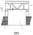
- the different elements component hull 1 are assembled in a building site and this shell 1 rests on supports 6 at a low distance from the ground, as shown in Figs. 7A to 7c.
- each load-bearing framework 10 is equipped, at the passage level of each member 21 of the sections 20 of the legs 2, a guide 12 of complementary shape to a portion circular of the corresponding member 21 and intended guiding the sections 20 during their vertical translation, as we will see later.
- the height of the lateral opening 11 and the distance between the lower part of the hull 1 with the ground form a space high enough to allow passage of a section 20.
- the means for lifting the first section 20 can be constituted for example by a crane or cylinders ..
- This first section 20 is then lifted by the motor-reducer 31 and pinion assemblies of outputs 32 so as to position the lower part of said first section 20 above the opening side 11, as shown in FIG. 7B.
- the lateral opening 11 thus being released, one engages in this lateral opening 11 a second section 20 and it is positioned in the axis of the first section 20 previously raised.
- these sections 20 are assembled by welding and are raised by means of said assemblies geared motors 31 and output pinions 32 to release the lateral opening 11 in order to allow the positioning of another section 20.
- the method according to the invention therefore makes it possible to simplify assembly and assembly operations legs of an oil rig and by consequently to reduce manufacturing costs.
- the method according to the invention makes it possible to reduce handling operations and avoid that the different sections assembly operations legs are dependent on the weather.
Landscapes
- Engineering & Computer Science (AREA)
- General Engineering & Computer Science (AREA)
- Mechanical Engineering (AREA)
- Civil Engineering (AREA)
- Structural Engineering (AREA)
- Wind Motors (AREA)
- Revetment (AREA)
- Vehicle Cleaning, Maintenance, Repair, Refitting, And Outriggers (AREA)
- Foundations (AREA)
- Earth Drilling (AREA)
- Vehicle Step Arrangements And Article Storage (AREA)
Claims (2)
- Verfahren zum Zusammenbau von Teilstücken von Beinstützen einer Ölplattform für den Einsatz auf See, in der Ausführung mit einem auf den Beinstützen (2) verstellbaren Rumpf (1), angetrieben durch eine Antriebsvorrichtung (30), die auf einem auf dem Rumpf (1) angebrachten Trägergerüst (10) angeordnet ist, wobei jede aus wenigstens zwei gegenüberliegenden Getriebemotorengruppen (31) besteht, welche Abtriebsritzel (32) antreiben, die mit gegenüberliegenden Zahnstangen (23) zusammenwirken, und wobei die Zahnstangen (23) auf den Beinstützen (2) angebracht sind, und jede dieser Beinstützen (2) den Rumpf (1) und das zugehörige Trägergerüst (10) durchläuft und aus übereinander angeordneten und durch Schweißen zusammengefügten Teilstücken (20) besteht, gekennzeichnet durch folgende Verfahrensschritte:auf der Höhe des Durchgangs einer jeden Beinstütze (2) wird eine seitliche Öffnung (11) im Rumpf (1) und in dem unteren Teil des Trägergerüstes (10) ausgespart,in jede seitliche Öffnung (11) wird ein erstes Teilstück (20) eingefügt und in der Mittellinie des Durchgangs (5) der Beinstütse (2) positioniert,das erste Teilstück (20) einer jeden Beinstütze (2) wird angehoben, um den oberen Bereich dieses Teilstücks (20) oberhalb der Öffnung (11) zu positionieren,die Getriebemotorengruppen (31) und Abtriebsritzel (32) werden auf den Zahnstangen (23) des ersten Teilstücks (20) angebracht,das erste Teilstück (20) wird mittels der Getriebemotorengruppen (31) und Abtriebsritzel (32) angehoben, um den unteren Teil dieses ersten Teilstückes (20) über die Öffnung (11) zu verfahren,in die Öffnung (11) wird ein zweites Teilstück (20) eingefügt und dieses gemäß der Mittellinie des ersten Teilstücks (20) ausgerichtet,die Teilstücke (20) werden aneinander angelegt,diese Teilstücke (20) werden miteinander durch Schweißen verbunden,diese Teilstücke (20) werden mittels der Getriebemotorengruppen (31) und Abtriebsritzel (32) angehoben,die Teilstücke (20) zur Bildung einer jeden Beinstütze (2) werden nacheinander in die Öffnung (11) eingefügt und miteinander verbunden,und die erstellten seitlichen Öffnungen (11) im Rumpf (1) werden wieder verschlossen.
- Verfahren gemäß Anspruch 1, dadurch gekennzeichnet, dass während des Anhebens der Teilstücke (20) der Beinstützen (2) diese Teilstücke (20) im Inneren eines jeden Tragergerüstes (10) seitlich geführt werden.
Applications Claiming Priority (2)
| Application Number | Priority Date | Filing Date | Title |
|---|---|---|---|
| FR9702763 | 1997-03-07 | ||
| FR9702763A FR2760474B1 (fr) | 1997-03-07 | 1997-03-07 | Procede d'assemblage de troncons de jambes de support d'une plate-forme petroliere |
Publications (2)
| Publication Number | Publication Date |
|---|---|
| EP0863260A1 EP0863260A1 (de) | 1998-09-09 |
| EP0863260B1 true EP0863260B1 (de) | 2003-04-02 |
Family
ID=9504532
Family Applications (1)
| Application Number | Title | Priority Date | Filing Date |
|---|---|---|---|
| EP98400103A Expired - Lifetime EP0863260B1 (de) | 1997-03-07 | 1998-01-20 | Verfahren zum Verbinden der Beingurte einer Ölplattform |
Country Status (8)
| Country | Link |
|---|---|
| US (1) | US5954453A (de) |
| EP (1) | EP0863260B1 (de) |
| DE (1) | DE69812754T2 (de) |
| EA (1) | EA000553B1 (de) |
| ES (1) | ES2195285T3 (de) |
| FR (1) | FR2760474B1 (de) |
| MY (1) | MY119478A (de) |
| NO (1) | NO316125B1 (de) |
Families Citing this family (12)
| Publication number | Priority date | Publication date | Assignee | Title |
|---|---|---|---|---|
| US5782733A (en) * | 1992-10-26 | 1998-07-21 | Innoflex Incorporated | Zippered film and bag |
| WO2012162800A1 (en) * | 2011-06-02 | 2012-12-06 | National Oilwell Varco, L.P. | Drilling rig system with self-elevating drill floor |
| DE102012016915B4 (de) * | 2012-08-22 | 2017-10-19 | Salzgitter Mannesmann Line Pipe Gmbh | Tragstruktur eines Offshore-Bauwerks, insbesondere einer Windenergieanlage, Verwendung einer derartigen Tragstruktur, sowie Verfahren zu deren Herstellung |
| WO2014182991A1 (en) | 2013-05-10 | 2014-11-13 | Devin International, Inc. | Drilling rig transfer system and method |
| WO2016008031A1 (en) | 2014-07-14 | 2016-01-21 | Dreco Energy Services Ulc | Mobile drilling rig |
| US9988807B2 (en) | 2016-02-24 | 2018-06-05 | National Oilwell Varco, L.P. | Drilling rig with self-elevating drill floor |
| WO2017155950A1 (en) | 2016-03-07 | 2017-09-14 | National Oilwell Varco, L.P. | Multi-well bop cellar trailer |
| US9970211B2 (en) | 2016-05-02 | 2018-05-15 | Dreco Energy Services Ulc | Guide rails for mobile drilling rig |
| US10293854B2 (en) | 2016-10-05 | 2019-05-21 | Dreco Energy Services Ulc | Movable rig and steering system |
| WO2020028969A1 (en) | 2018-08-06 | 2020-02-13 | Dreco Energy Services Ulc | Drill floor support structures |
| CN109648269B (zh) * | 2019-01-02 | 2021-07-09 | 南通泰胜蓝岛海洋工程有限公司 | 一种海洋生活平台的提升腿桩建造工艺 |
| US11603723B2 (en) | 2019-08-30 | 2023-03-14 | Nov Canada Ulc | Cuttings processing unit |
Family Cites Families (8)
| Publication number | Priority date | Publication date | Assignee | Title |
|---|---|---|---|---|
| US3014346A (en) * | 1957-09-10 | 1961-12-26 | Jersey Prod Res Co | Method and means for raising and lowering a platform |
| US3183676A (en) * | 1960-10-20 | 1965-05-18 | Robert G Letourneau | Mobile sea platform |
| US3727414A (en) * | 1971-06-28 | 1973-04-17 | Bowden Drilling Services Ltd | Off shore drilling platform construction |
| US4266887A (en) * | 1977-06-10 | 1981-05-12 | Brown & Root, Inc. | Self-elevating fixed platform |
| US4255069A (en) * | 1979-08-01 | 1981-03-10 | The Offshore Company | Jack-up platform locking apparatus |
| US4269543A (en) * | 1979-08-29 | 1981-05-26 | Freiede & Goldman, Ltd. | Mobile, offshore, self-elevating (jack-up) unit leg/hull rigidification system |
| JPS6047410B2 (ja) * | 1980-02-22 | 1985-10-22 | 三井造船株式会社 | 着地昇降式海上作業台の試験方法 |
| FR2734851B1 (fr) * | 1995-06-02 | 1999-03-05 | Technip Geoproduction | Plate-forme auto-elevatrice de forage ou d'exploitation petroliere en mer. |
-
1997
- 1997-03-07 FR FR9702763A patent/FR2760474B1/fr not_active Expired - Fee Related
-
1998
- 1998-01-20 EP EP98400103A patent/EP0863260B1/de not_active Expired - Lifetime
- 1998-01-20 ES ES98400103T patent/ES2195285T3/es not_active Expired - Lifetime
- 1998-01-20 DE DE69812754T patent/DE69812754T2/de not_active Expired - Fee Related
- 1998-02-03 US US09/018,303 patent/US5954453A/en not_active Expired - Lifetime
- 1998-03-04 MY MYPI98000954A patent/MY119478A/en unknown
- 1998-03-05 NO NO19980961A patent/NO316125B1/no not_active IP Right Cessation
- 1998-03-06 EA EA199800195A patent/EA000553B1/ru not_active IP Right Cessation
Also Published As
| Publication number | Publication date |
|---|---|
| DE69812754D1 (de) | 2003-05-08 |
| EA199800195A1 (ru) | 1998-10-29 |
| EP0863260A1 (de) | 1998-09-09 |
| NO316125B1 (no) | 2003-12-15 |
| ES2195285T3 (es) | 2003-12-01 |
| FR2760474A1 (fr) | 1998-09-11 |
| DE69812754T2 (de) | 2004-03-18 |
| FR2760474B1 (fr) | 1999-05-28 |
| NO980961D0 (no) | 1998-03-05 |
| EA000553B1 (ru) | 1999-10-28 |
| US5954453A (en) | 1999-09-21 |
| NO980961L (no) | 1998-09-08 |
| MY119478A (en) | 2005-05-31 |
Similar Documents
| Publication | Publication Date | Title |
|---|---|---|
| EP0863260B1 (de) | Verfahren zum Verbinden der Beingurte einer Ölplattform | |
| EP1716293B1 (de) | Verfahren und Vorrichtung zum Demontieren einer Ölplattform | |
| EP0090006B1 (de) | Schwimmende vorrichtung und verfahren zum heben und fördern von lasten | |
| EP2435293B1 (de) | Struktur zum transportieren, installieren und demontieren des decks einer plattform und verfahren zum transportieren, installieren und demontieren eines solches decks | |
| EP2307269A2 (de) | Struktur zur offshore-installation mindestens einer windturbine oder eines unterwassergenerators und verfahren für den transport und die offshore-installation mindestens einer windturbine oder eines unterwassergenerators | |
| WO2003080425A1 (fr) | Structure de transport, d'installation et de demantelement d'un pont d'une plate-forme petroliere fixe et procede de mise en oeuvre d'une telle structure | |
| EP2091808B1 (de) | Einrichtung und methode zum transport, montage und demontage der brücke einer off-shore platform | |
| EP0745729B1 (de) | Selbsthebende Plattform für Bohren oder Ölgewinnung aus dem Meer | |
| CH663443A5 (fr) | Installation pour coffrage du beton. | |
| FR2949826A1 (fr) | Turbomachine hydraulique a maintenance simple | |
| WO2006037870A1 (fr) | Procede d'installation des jambes sur un pont d'une plate-forme d'exploitation en mer | |
| EP0014661B1 (de) | Vorrichtung zum Einbau eines Kernreaktorblocks in ein Schiff | |
| EP0645496B1 (de) | Verfahren und Vorrichtung für die Montage der Beingurte einer Ölplatform | |
| FR2908733A1 (fr) | Structure de transport, d'installation et de demantelement d'un pont d'une plate-forme petroliere et procedes de mise en oeuvre d'une telle structure. | |
| WO1979000016A1 (fr) | Procedure de mise en place d'une structure support de torchere pour plate-forme petroliere | |
| FR2486561A1 (fr) | Procede de montage en eau relativement peu profonde, ou moyennement profonde, et d'installation sur le site d'exploitation, d'une plate-forme de forage et de production petroliere a embase-poids | |
| CA1281555C (fr) | Plate-forme semi-submersible, notamment pour la recherche et/ou l'exploitation de gisements sous- marins en mers froides | |
| WO2003055739A1 (fr) | Procede de montage d'un equipement pesant sur la coque d'un navire | |
| WO2009007610A2 (fr) | Installation de reception d'une structure apte a etre prise en charge par un vehicule porteur equipe d'un bras ou d'une rampe de manipulation | |
| FR2604413A1 (fr) | Procede de placement d'une plate-forme de forage et d'exploitation en mer, d'un site a un autre | |
| FR3140065A1 (fr) | Plateforme flottante off-shore pour fabrication, assemblage, maintenance et/ou démontage d’éoliennes flottantes | |
| FR2770237A1 (fr) | Procede pour rehausser une plate-forme marine | |
| FR2719615A1 (fr) | Procédé d'assemblage de tronçons de grande longueur de membrures des jambes de support d'une plate-forme pétrolière. | |
| FR2668848A2 (fr) | Procede et dispositif de demantelement d'un composant irradie d'un reacteur nucleaire par decoupage de sa paroi. | |
| EP0252840A1 (de) | Ölplattform zum Bohren und zur Nutzung des Meeres |
Legal Events
| Date | Code | Title | Description |
|---|---|---|---|
| PUAI | Public reference made under article 153(3) epc to a published international application that has entered the european phase |
Free format text: ORIGINAL CODE: 0009012 |
|
| AK | Designated contracting states |
Kind code of ref document: A1 Designated state(s): DE ES FI FR GB IE IT NL |
|
| AX | Request for extension of the european patent |
Free format text: AL;LT;LV;MK;RO;SI |
|
| 17P | Request for examination filed |
Effective date: 19980915 |
|
| AKX | Designation fees paid |
Free format text: DE ES FI FR GB IE IT NL |
|
| AXX | Extension fees paid |
Free format text: LT PAYMENT 19980915;LV PAYMENT 19980915;SI PAYMENT 19980915 |
|
| RBV | Designated contracting states (corrected) |
Designated state(s): DE ES FI FR GB IE IT NL |
|
| RAP1 | Party data changed (applicant data changed or rights of an application transferred) |
Owner name: TECHNIP FRANCE |
|
| GRAH | Despatch of communication of intention to grant a patent |
Free format text: ORIGINAL CODE: EPIDOS IGRA |
|
| GRAH | Despatch of communication of intention to grant a patent |
Free format text: ORIGINAL CODE: EPIDOS IGRA |
|
| GRAA | (expected) grant |
Free format text: ORIGINAL CODE: 0009210 |
|
| AK | Designated contracting states |
Designated state(s): DE ES FI FR GB IE IT NL |
|
| AX | Request for extension of the european patent |
Extension state: LT LV SI |
|
| PG25 | Lapsed in a contracting state [announced via postgrant information from national office to epo] |
Ref country code: IE Free format text: LAPSE BECAUSE OF NON-PAYMENT OF DUE FEES Effective date: 20030402 |
|
| REG | Reference to a national code |
Ref country code: GB Ref legal event code: FG4D Free format text: NOT ENGLISH |
|
| REG | Reference to a national code |
Ref country code: IE Ref legal event code: FG4D Free format text: FRENCH |
|
| REF | Corresponds to: |
Ref document number: 69812754 Country of ref document: DE Date of ref document: 20030508 Kind code of ref document: P |
|
| GBT | Gb: translation of ep patent filed (gb section 77(6)(a)/1977) |
Effective date: 20030728 |
|
| LTIE | Lt: invalidation of european patent or patent extension |
Effective date: 20030402 |
|
| REG | Reference to a national code |
Ref country code: IE Ref legal event code: FD4D Ref document number: 0863260E Country of ref document: IE |
|
| PLBE | No opposition filed within time limit |
Free format text: ORIGINAL CODE: 0009261 |
|
| STAA | Information on the status of an ep patent application or granted ep patent |
Free format text: STATUS: NO OPPOSITION FILED WITHIN TIME LIMIT |
|
| 26N | No opposition filed |
Effective date: 20040105 |
|
| PG25 | Lapsed in a contracting state [announced via postgrant information from national office to epo] |
Ref country code: FR Free format text: LAPSE BECAUSE OF NON-PAYMENT OF DUE FEES Effective date: 20060131 |
|
| REG | Reference to a national code |
Ref country code: FR Ref legal event code: ST Effective date: 20060929 |
|
| REG | Reference to a national code |
Ref country code: FR Ref legal event code: RN |
|
| REG | Reference to a national code |
Ref country code: FR Ref legal event code: FC |
|
| PGRI | Patent reinstated in contracting state [announced from national office to epo] |
Ref country code: FR Effective date: 20070117 |
|
| PGFP | Annual fee paid to national office [announced via postgrant information from national office to epo] |
Ref country code: DE Payment date: 20090130 Year of fee payment: 12 |
|
| PGFP | Annual fee paid to national office [announced via postgrant information from national office to epo] |
Ref country code: GB Payment date: 20081211 Year of fee payment: 12 |
|
| PGFP | Annual fee paid to national office [announced via postgrant information from national office to epo] |
Ref country code: IT Payment date: 20090128 Year of fee payment: 12 |
|
| GBPC | Gb: european patent ceased through non-payment of renewal fee |
Effective date: 20100120 |
|
| PG25 | Lapsed in a contracting state [announced via postgrant information from national office to epo] |
Ref country code: DE Free format text: LAPSE BECAUSE OF NON-PAYMENT OF DUE FEES Effective date: 20100803 |
|
| PG25 | Lapsed in a contracting state [announced via postgrant information from national office to epo] |
Ref country code: GB Free format text: LAPSE BECAUSE OF NON-PAYMENT OF DUE FEES Effective date: 20100120 |
|
| PG25 | Lapsed in a contracting state [announced via postgrant information from national office to epo] |
Ref country code: IT Free format text: LAPSE BECAUSE OF NON-PAYMENT OF DUE FEES Effective date: 20100120 |
|
| REG | Reference to a national code |
Ref country code: FR Ref legal event code: PLFP Year of fee payment: 18 |
|
| PGFP | Annual fee paid to national office [announced via postgrant information from national office to epo] |
Ref country code: FI Payment date: 20141217 Year of fee payment: 18 |
|
| PGFP | Annual fee paid to national office [announced via postgrant information from national office to epo] |
Ref country code: NL Payment date: 20141218 Year of fee payment: 18 |
|
| PGFP | Annual fee paid to national office [announced via postgrant information from national office to epo] |
Ref country code: ES Payment date: 20150126 Year of fee payment: 18 |
|
| PGFP | Annual fee paid to national office [announced via postgrant information from national office to epo] |
Ref country code: FR Payment date: 20150129 Year of fee payment: 18 |
|
| REG | Reference to a national code |
Ref country code: NL Ref legal event code: MM Effective date: 20160201 |
|
| REG | Reference to a national code |
Ref country code: FR Ref legal event code: ST Effective date: 20160930 |
|
| PG25 | Lapsed in a contracting state [announced via postgrant information from national office to epo] |
Ref country code: FI Free format text: LAPSE BECAUSE OF NON-PAYMENT OF DUE FEES Effective date: 20160120 |
|
| PG25 | Lapsed in a contracting state [announced via postgrant information from national office to epo] |
Ref country code: NL Free format text: LAPSE BECAUSE OF NON-PAYMENT OF DUE FEES Effective date: 20160201 Ref country code: FR Free format text: LAPSE BECAUSE OF NON-PAYMENT OF DUE FEES Effective date: 20160201 |
|
| REG | Reference to a national code |
Ref country code: ES Ref legal event code: FD2A Effective date: 20170227 |
|
| PG25 | Lapsed in a contracting state [announced via postgrant information from national office to epo] |
Ref country code: ES Free format text: LAPSE BECAUSE OF NON-PAYMENT OF DUE FEES Effective date: 20160121 |