EP0863023B1 - Füllminenstift mit zwei Spannbacken - Google Patents
Füllminenstift mit zwei Spannbacken Download PDFInfo
- Publication number
- EP0863023B1 EP0863023B1 EP97310618A EP97310618A EP0863023B1 EP 0863023 B1 EP0863023 B1 EP 0863023B1 EP 97310618 A EP97310618 A EP 97310618A EP 97310618 A EP97310618 A EP 97310618A EP 0863023 B1 EP0863023 B1 EP 0863023B1
- Authority
- EP
- European Patent Office
- Prior art keywords
- chuck
- lead
- eraser
- adapter
- barrel
- Prior art date
- Legal status (The legal status is an assumption and is not a legal conclusion. Google has not performed a legal analysis and makes no representation as to the accuracy of the status listed.)
- Expired - Lifetime
Links
Images


Classifications
-
- B—PERFORMING OPERATIONS; TRANSPORTING
- B43—WRITING OR DRAWING IMPLEMENTS; BUREAU ACCESSORIES
- B43K—IMPLEMENTS FOR WRITING OR DRAWING
- B43K21/00—Propelling pencils
-
- B—PERFORMING OPERATIONS; TRANSPORTING
- B43—WRITING OR DRAWING IMPLEMENTS; BUREAU ACCESSORIES
- B43K—IMPLEMENTS FOR WRITING OR DRAWING
- B43K21/00—Propelling pencils
- B43K21/02—Writing-core feeding mechanisms
- B43K21/16—Writing-core feeding mechanisms with stepwise feed of writing-cores
- B43K21/20—Writing-core feeding mechanisms with stepwise feed of writing-cores with writing-cores automatically replaced from magazines
-
- B—PERFORMING OPERATIONS; TRANSPORTING
- B43—WRITING OR DRAWING IMPLEMENTS; BUREAU ACCESSORIES
- B43K—IMPLEMENTS FOR WRITING OR DRAWING
- B43K21/00—Propelling pencils
- B43K21/02—Writing-core feeding mechanisms
- B43K21/22—Writing-cores gripping means, e.g. chucks
-
- B—PERFORMING OPERATIONS; TRANSPORTING
- B43—WRITING OR DRAWING IMPLEMENTS; BUREAU ACCESSORIES
- B43K—IMPLEMENTS FOR WRITING OR DRAWING
- B43K29/00—Combinations of writing implements with other articles
- B43K29/02—Combinations of writing implements with other articles with rubbers
Definitions
- the present invention relates to a double-chuck mechanical pencil provided with a front chuck for gripping a lead, and a back chuck provided with a chuck ring loosely put thereon to project a lead by a fixed length and, more particularly, to a double-chuck mechanical pencil provided with an eraser support structure in its back portion.
- EP0715968 discloses a double chuck mechanical pencil which includes features according to the pre-characterising portion of the independent claims of this application.
- a double-chuck mechanical pencil with an eraser having a barrel, a lead tank, an adapter combined with the barrel and the lead tank so that chucks are able to slide axially and unable to rotate, and restraining means provided on the adapter and a rubber eraser support member to prevent the torsional breakage of a lead.
- a mechanical pencil of this kind has complicated internal mechanisms and a sufficient space for containing an eraser cannot be secured in a back portion of the barrel of the mechanical pencil. Such a problem is more serious in a double-chuck mechanical pencil provided with a lead holding chuck and a lead advancing chuck to reduce waste leads.
- Pencil marks drawn on a paper sheet with the mechanical pencil can be rubbed out with an eraser, because scraps of rubber are produced when the surface of the paper sheet is rubbed with the eraser, and the scraps of rubber adsorb and envelop carbon particles forming the pencil marks. Therefore, the eraser is abraded and worn out rapidly.
- the present invention has been made taking into consideration the complicated structure of double-chuck mechanical pencils and the characteristics of the eraser and it is an object of the present invention to enable an eraser projecting mechanism to be easily removed regardless of the change in shape of the eraser and to enable the eraser to be projected by an appropriate length when the same is abraded.
- Another object of the present invention is to eliminate structural disadvantages of an eraser, to enable the use of either of a plastic eraser and a rubber eraser without trouble, to overcome difficulty in directly removing a worn or deteriorated eraser when replenishing the mechanical pencil with leads, and to provide an eraser support structure capable of being easily removed without making finger tips dirty with a dirty eraser.
- a third object of the present invention is to enable an eraser to be put relatively easily on a back portion of a mechanical pencil regardless of the size and the shape thereof and manufacturing errors therein, to enable the mechanical pencil to be replenished easily and accurately with leads, to avoid torsionally breaking a lead chucked in a front lead chuck and a back lead chuck by the turning of the back lead chuck together with a lead tank turned by the eraser when the eraser is used.
- a fourth object of the present invention is to prevent a lead from being held in a space between a barrel and a lead tank of a diameter different from that of the barrel, and the lead tank from rattling when an eraser is used by providing an adapter serving as a spacer between the barrel and the lead tank.
- a double-chuck mechanical pencil comprising:
- the rotary eraser projecting mechanism is replaced with an eraser support structure.
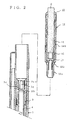
- a head cap 2 is screwed into the forward end of a barrel 1
- a lead tank 4 is inserted axially slidably in the barrel 1
- an adapter 3 is fixed to a back end of the lead tank 4 to restrain the lead tank 4 from turning relative to the barrel 1.
- a back lead chuck 5 for advancing a lead is fixedly forced into a front end portion of the lead tank 4, and a chuck ring 6 is loosely put on the front end portion of the back lead chuck 5.
- An elastic tube 7 is disposed in contact with the back end of the chuck ring 6, and a back spring 8, i.e., an elastic member, is extended between the elastic tube 7 and the front end of the lead tank 4.
- the elastic tube 7 is provided with an inner flange 7a at its front end, and the front end of the back spring 8 is seated on the inner flange 7a.
- the back spring 8 biases the lead tank 4 backward relative to the barrel 1.
- a connector 9 is put on the elastic tube 7 by a stopping structure so as to sheathe the elastic tube 7 therein.
- a front spring 10 is extended between a reduced front end portion of the connector 9 and the inner surface of the head cap 2 to bias the connector 9 backward.
- a front lead chuck 11 for holding the lead is fixedly forced in a front end of the reduced portion of the connector 9.
- the elasticity of the front spring 10 is preset so as to be weaker than that of the back spring 8.
- the front lead chuck 11 when advanced relative to the head cap 2, holds the lead by a holding force adequate to prevent the lead from falling off the front lead chuck 11 and to permit the lead to move if an axial force is applied to the lead.
- the front lead chuck 11 is provided with a circumferential stopping shoulder 11a in a portion thereof projecting from the tip of the head cap 2.
- the front lead chuck 11 when retracted relative to the head cap 2, is capable of exerting a holding force on the lead to hold the lead immovably against a pressure that acts on the lead during writing.
- indicated at 12 is a unit rotary eraser projecting mechanism disposed behind the lead tank 4.
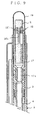
- the adapter 3 is fixed to the back portion of the lead tank 4.
- the adapter 3 is provided on its outer circumference with four longitudinal ribs 3a arranged at equal angular intervals.
- Each of the longitudinal ribs 3a has a tapered front end 3aa, which serves as a guide when the adapter 3 is inserted in the barrel 1 so that the longitudinal ribs 3a engage with longitudinal ribs 1a formed on the inner circumference of the barrel 1. Therefore, the adapter 3 need not be positioned at a specific angular position relative to the barrel 1 when assembling the barrel 1 and the adapter 3.
- the adapter 3 is provided in the middle portion of the inner circumference thereof with a circular ridge 3b for positioning a support member 13 of the rotary eraser projecting mechanism 12.
- Longitudinal ribs 3c for restraining the adapter 3 from turning is extended behind the circular ridge 3b.
- Each of the longitudinal ribs 3c has a tapered back end 3cc which serves, similarly to the tapered front end 3aa, as a guide when engaging the longitudinal ribs 3c with longitudinal ribs 13b formed on the support member 13.
- the inner edge of the front end of the adapter 3 is chamfered in a bevel surface 3d to facilitate the insertion of the back end of the lead tank 4 into the front end of the adapter 3 during assembly of the mechanical pencil. Also, the inner edge of the back end of the adapter 3 is chamfered in a bevel surface 3d' to facilitate the replenishment of the lead tank 4 with leads and the insertion of the support member 13 of the rotary eraser projecting mechanism 12 into the back end of the adapter 3.
- the circular rib 3b formed in the middle portion of the inner circumference of the adapter 3 has a bevel back surface 3e expanded toward the back so that leads can be smoothly supplied into the lead tank 4.
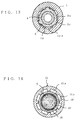
- the barrel 1 is provided on its inner circumference with four longitudinal ribs 1a arranged at equal angular intervals to restrain the adapter 3 from turning relative to the barrel 1.
- the longitudinal ribs 1a of the barrel 1 and the longitudinal ribs 3a of the adapter 3 are engaged as shown in Figs. 4 and 5.
- the position and the length of the longitudinal ribs 1a of the barrel 1 are determined properly taking into consideration the stroke of the lead tank 4 which is pushed to project the lead.
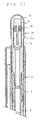
- the support member 13 included in the eraser projecting mechanism 12 includes a substantially tubular portion 13' and a leg portion 13a provided on its outer circumference with the longitudinal ribs 13b (Figs. 6 and 7).
- the longitudinal ribs 13b are engaged with the longitudinal ribs 3c (Fig. 2) extended backward from the circular rib 3b.
- the outer edge of the front end of the leg portion 13a of the support member 13 is chamfered to form a bevel surface 13c mating with the bevel back surface 3e of the circular rib 3b.
- the support member 13, the circular rib 3b of the adapter 3 and the lead tank 4 are formed so that their inside diameters are substantially the same to facilitate the movement of leads through the support member 13 and the lead tank 4.
- a helical groove 14b i.e., a helical means, is formed in the inner circumference of a guide tube 14 (Fig. 1) rotatably mounted on the tubular portion 13' of the support member 13.
- the four longitudinal ribs 13b are arranged on the leg portion 13a of the support member 13 at equal angular intervals.
- Each of the longitudinal ribs 13b has a tapered front end 13bb.
- a pair of longitudinal slots 13d are formed behind the longitudinal ribs 13b in the support member 13.
- An eraser holding member 15 is movably inserted in the tubular portion 13' of the support member 13.
- the holding member 15 is provided with projections 15a.
- the projections 15a of the eraser holding member 15 are projected outward through the slots 13d and engaged with the helical groove 14b of the guide tube 14.
- Projections 13e are formed by raising portions of the support member 13.
- the projections 13e are engaged with an inwardly facing flange 14a formed on the guide tube 14.
- a restraining means for restraining the leg portion 13a of the support member 13 from turning and allowing the same to move axially comprises the four longitudinal ribs 3c (Fig. 2) formed at equal angular intervals on the inner circumference of the adapter 3, and the longitudinal ribs 13b formed on the outer circumference of the leg portion 13a of the support member 13 and in engagement with the longitudinal ribs 3c of the adapter 3.
- the operation of the double-chuck mechanical pencil in the first embodiment will be described hereinafter.
- the back end of the eraser projecting mechanism 12 is pushed by a user's finger.
- First the front spring 10 is compressed since the front spring 10 is weaker in elasticity than the back spring 8 as discussed above, so that the front lead chuck 11 is advanced and opens in a state for receiving a lead through its back end.
- the tapered shoulder 9a of the connector 9 comes into contact with a step 2a formed in the inner surface of the head cap 2, and then the back spring 8 is compressed to advance the back lead chuck 5 together with the lead tank 4.
- the chuck ring 6 comes into contact with a step 9b formed on the inner circumference of the connector 9, so that the back lead chuck 5 is opened to allow a lead to be advanced.
- the eraser projecting mechanism 12 is released from the user's finger.
- the back lead chuck 5 is returned to its initial position.
- the eraser projecting mechanism 12 is pushed again to advance the back lead chuck 5.
- the back lead chuck 5 holding the lead advances in the connector 9 to advance the lead through the front lead chuck 11.
- the lead is advanced further through the front lead chuck 11 and is projected from the front lead chuck 11.
- the eraser projecting mechanism 12 is pushed to feed the lead so that the lead is advanced by an appropriate distance.
- the foregoing eraser projecting mechanism pushing operation is repeated to feed a new lead to push the abraded lead out through the front lead chuck 11 by the new lead.
- the lead can be pushed back into the double-chuck mechanical pencil by pushing the eraser projecting mechanism 12 to open the lead chucks 5 and 11 slightly and pressing the lead at its point so that the lead is projected from the front lead chuck 11 by an appropriate length to avoid the breakage of the lead.
- the barrel 1 is held fast and the guide tube 14 is turned relative to the barrel 1 to project an eraser from the eraser projecting mechanism 12. Since the support member 13 of the eraser projecting mechanism 12 is restrained from turning relative to the adapter 3 by the engagement of the longitudinal ribs 13b and 3c, the eraser holding member 15 is driven by the helical groove 14b of the guide tube 14 so as to move backward along the slots 13c of the support member 13 when the guide tube 14 is turned, so that a portion of the eraser is projected from the back end of the guide tube 14.
- a considerably large torque acts on the eraser when the eraser is used to rub the surface of a paper sheet. Since the support member 13 is restrained from turning relative to the adapter 3 by the engagement of the longitudinal ribs 13b and 3c, and the adapter 3 is restrained from turning relative to the barrel 1 by the engagement of the longitudinal ribs 3c and 1a, the torque acting on the eraser is not transmitted to the back lead chuck 5 connected to the lead tank 4, and the back lead chuck 5 is not turned relative to the front lead chuck 11, so that the lead gripped by the back lead chuck 5 and the front lead chuck 11 will not be torsionally broken.
- the adapter 3 serves also as a spacer for avoiding difficulty in erasing pencil marks with the eraser due to the unsteady movement of the support member 13 and lead tank 4.
- the guide tube 14 is turned in the reverse direction to retract the eraser into the support member 13.
- the leg portion 13a of the support member 13 is pulled out of the adapter 3 fixed to the back portion of the lead tank 4 by pulling the guide tube 14. Since the eraser projecting mechanism 12 is formed in a unit, and the leg portion 13a of the support member 13 is simply inserted in the adapter 3 so that the longitudinal ribs are engaged, the eraser projecting mechanism 12 can be easily removed simply by pulling the guide tube 14. Since the bevel surfaces 3d and 3e are formed at the opposite ends of the adapter 3, new leads can be smoothly supplied through the open back end of the barrel 1 through the adapter 3 into the lead tank 4.
- Fig. 8 is a longitudinal sectional view of a double-chuck mechanical pencil in a second embodiment according to the present invention.
- Mechanisms including a front lead chuck and a back lead chuck and formed in a front portion of the double-chuck mechanical pencil are the same as the corresponding mechanisms of the double-chuck mechanical pencil in the first embodiment and hence the description thereof will be omitted.
- the double-chuck mechanical pencil in the second embodiment is provided with an eraser support structure 16 instead of the rotary eraser projecting mechanism 12 of the first embodiment.
- the eraser support structure 16 comprises a tubular support member 17 having a leg portion 17a provided on its outer circumference with longitudinal ribs similar to the longitudinal ribs 13b of the support member 13 employed in the first embodiment, and a bottomed,eraser jacket 18 fitted in a bore formed in a back portion of the support member 17.
- An eraser jacketed by the eraser jacket 18 is covered with a push cap 19 detachably inserted in an annular space between a barrel 1 and the support member 17.
- the double-chuck mechanical pencil in the second embodiment advances and projects a lead when the push cap 19 is pushed.
- the push cap 19 is removed.
- the eraser jacket 18 jacketing the eraser is removed from the support member 17, the eraser jacket 18 provided with a slit 18a is expanded elastically to expand the slit 18a so that the eraser is able to move relative to the eraser jacket 18, a proper length of the eraser is pulled out from the eraser jacket 18, and then the eraser jacket 18 is allowed to return to its natural shape to hold the eraser.
- the lead tank 4 can be replenished with spare leads without touching the eraser and without removing the eraser from the eraser support structure 16 by removing the push cap 19 and pulling out the eraser support structure 16.
- Fig. 9 is a fragmentary longitudinal sectional view of an eraser jacket 18' in a modification of the eraser jacket 18 shown in Fig. 8.
- the eraser jacket 18' is bottomless and has a C-shaped cross section.
- An eraser support structure 16 shown in Fig. 9 employing the jacket 18' needs a less number of parts than the rotary eraser projecting mechanism shown in Fig. 1, is able to employ an eraser of a diameter greater than that of the eraser employed in the rotary eraser projecting mechanism shown in Fig. 1, and is able to employ an eraser longer than that employed in the eraser support structure 16 employing the eraser jacket 18.
- the eraser jacket 18' Since the eraser jacket 18' is bottomless, the eraser jacket 18' is held at the back end of a support member 17 with an eraser jacketed by the eraser jacket 18' inserted into the depth of the support member 17.
- the eraser jacket 18' jacketing the eraser When a back portion of the eraser projecting from the eraser jacket 18' is abraded, the eraser jacket 18' jacketing the eraser is removed from the support member 17, the eraser jacket 18' provided with a slit 18a' is expanded elastically to expand the slit 18a' so that the eraser is able to move relative to the eraser jacket 18', a proper length of the eraser is pulled out from the eraser jacket 18', the eraser jacket 18' is allowed to return to its natural shape to hold the eraser, and then the eraser jacket 18' is put on the support member 17.
- Fig. 10 shows a barrel 1 in a modification of the barrel 1 shown in Fig. 8.
- the barrel 1 shown in Fig. 10 is provided with a pair of recesses 1b in its back end to facilitate the removal of the eraser support structure 16.
- the support member 17 can be further firmly held between fingers when removing the eraser support structure 16 from the barrel 1 to replenish the lead tank 4 with spare leads.
- a push cap 19 is detachably fitted in a rear end portion of the support member 17.
- the fit between the push cap 19 and the support member 17 must be looser than that between the adapter 3 and the support member 17. More specifically, it is desirable that a force necessary for pulling off the push cap 19 from the support member 17 is in the range of 100 g to 400 g, and a force necessary for pulling the support structure from the adapter 3 is in the range of 800 g to 1000 g. If a force necessary for separating the adapter 3 from the lead tank 4 is 2000 g or above, the reverse fit between the push cap 19 or the support member 17, and will never occur.
- Fig. 11 is a fragmentary longitudinal sectional view of an eraser support structure 16 in a modification of the eraser support structure 16 shown in Fig. 8.
- a push cap 19 is detachably put on a back portion of a support member 17 included in the eraser support structure 16 in a manner different from that in which the push cap 19 of the foregoing embodiment is put on the support member 17.
- the push cap is put on the back portion of the support member 17 with its lower end seated on a flange 17b formed in a portion of the support member 17 projecting from the back end of a barrel 1.
- the barrels 1 shown in Figs. 8, 9 and 11 may be provided in their back ends with recesses similar to the recesses 1b shown in Fig. 10.
- the eraser support structure 16 can be easily removed from the barrel 1 by holding the support member 17 with fingers in the portion of thereof projecting from the barrel 1 without removing the push cap 19 from the support member 17.
- the flange 17a facilitate seizing hold of the support member 17 with fingers and pulling out the support member 17 from the barrel 1.
- any suitable number of longitudinal ribs may be used and any suitable restraining means for such a purpose other than the restraining means employing the longitudinal ribs may be employed.
- a support member, an adapter and a barrel respectively having polygonal cross sections may be used in combination.
- Fig. 12 is a longitudinal sectional view of a double-chuck mechanical pencil in a third embodiment according to the present invention.
- Mechanisms including a front lead chuck and a back lead chuck and formed in a front portion of the double-chuck mechanical pencil of Fig. 12 are the same as the corresponding mechanisms of the double-chuck mechanical pencil in the first embodiment shown in Fig. 1 and hence the description thereof will be omitted.
- an adapter 3 has an expanded front portion 3x, a back end portion of a lead tank 4 is forced into the expanded front end portion 3x of the adapter 3, and an eraser holding member 20 is fixedly pressed in a back end portion of the adapter 3.
- the inner edge of the front end of the adapter 3 is beveled in a taper surface 3xx to facilitate the insertion of the lead tank 4 in the expanded front end portion 3x of the adapter 3.
- An internal thread 1x is formed in a back end portion Of the barrel 1, an externally threaded portion 21x of an end cap 21 is screwed in the back end portion of the barrel 1, and ring 23a of a clip 23 is held between the back end of the barrel 1 and the end cap 21.
- An eraser jacket 18 jacketing an eraser is detachably attached to the eraser holding member 20.
- a push cap 19 is detachably put on the eraser holding member 20 so as to cover the eraser jacketed by the eraser jacket 18.
- three longitudinal ribs 3y are formed in the outer circumference of the expanded portion 3x of the adapter 3, and six longitudinal grooves 1yy are formed in a thick portion 1 y of the barrel 1 corresponding to the expanded portion 3x of the adapter 3.
- the longitudinal ribs 3y are fitted in the longitudinal grooves 1yy to restrain the adapter 3 from turning relative to the barrel 1.
- the diameter of a cylindrical surface including the bottoms of the longitudinal grooves 1yy is equal to that of the inner circumference indicated by dotted lines in Fig. 13 of a portion of the barrel 1 contiguous with the thick portion 1y so that any step may not be formed between the thick portion 1y and the portion contiguous with the thick portion 1y.
- the thick portion 1y has an inside diameter smaller than that of the portion contiguous with the thick portion 1y by a value necessary for forming the longitudinal grooves 1yy to achieve a function to allow the axial sliding movement of the expanded portion 3x of the adapter 3 in the barrel 1 and to restrain the turning of the adapter 3 relative to the barrel 1.
- the adapter 3 is able to move axially in the barrel 1, but is unable to turn relative to the barrel 1. Consequently, the adapter 3 does not turn relative to the barrel 1 even if a torque acts on the eraser holding member 20, and the lead gripped by the back lead chuck 5 and the front lead chuck 11 (Fig. 1) is never torsionally broken.
- the adapter 3 can be relatively easily inserted in the barrel 1 when assembling the double-chuck mechanical pencil shown in Fig. 12.
- the six longitudinal grooves 1yy are effective in preventing the formation of sink marks when molding the barrel 1.
- indicated at 1z is a circular rib formed on the inner circumference of the barrel 1 to prevent the rattling of the adapter 3 in the barrel 1.
- the lead tank 4 can be easily replenished with spare leads simply by removing the push cap 19 and the eraser jacket 18 jacketing the eraser.
- Fig. 14 shows a double-chuck mechanical pencil in a modification of the double-chuck mechanical pencil shown in Fig. 12.
- the double-chuck mechanical pencil is provided with a push cap 19 different from that of the double-chuck mechanical pencil shown in Fig. 12.
- two circular ridges 19a are formed on the outer circumference of the push cap 19 at a position corresponding to the inner circumference of the end cap 21, and an elastic O ring 22 is put in a circular groove between the two circular ridges 19a.
- the O ring 22 and the circular ridges 19a enable the push cap 19 to move smoothly without rattling.
- Fig. 15 shows a double-chuck mechanical pencil in another modification of the double-chuck mechanical pencil of Fig. 12.
- An end cap 21 shown in Fig. 15 is formed by molding a synthetic resin or by die casting.
- the end cap 21 is provided with eight longitudinal grooves 21a in its inner circumference as shown in Fig. 16 to avoid the formation of sink marks.
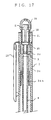
- Fig. 17 shows a double-chuck mechanical pencil in a modification of the double-chuck mechanical pencil of Fig. 15.
- the double-chuck mechanical pencil shown in Fig. 17 is provided with an arrangement to avoid a difficulty in smoothly sliding the adapter 3 relative to the barrel 1 attributable to the expansion of the adapter 3 caused by the lead tank 4 forced into the adapter 3.
- the longitudinal ribs 3y to be engaged with the longitudinal grooves 1yy of the barrel 1 are formed in a portion of the adapter 3 different from a portion of the same in which the lead tank 4 is inserted by a press fit, and a taper surface 3xx is formed in a portion of the inner circumference of the adapter 3 corresponding to the longitudinal ribs 3y.
- the expanded portion 3x of the adapter 3 is relatively long and a longer back portion of the lead tank 4 is forced in the expanded portion 3x of the adapter 3. Therefore, a portion of the adapter 3 in which the lead tank 4 is fitted by a high press fit to cause the same portion to expand is far behind the portion of the adapter 3 in which the longitudinal ribs 3y fitted in the longitudinal grooves 1yy of the barrel 1 are formed.
- a taper surface 3xx tapering backward is formed in a portion of the inner circumference of the adapter 3 corresponding to a portion of the outer circumference of the same in which the longitudinal ribs 3y are formed to secure a space between the adapter 3 and the lead tank 4.
- the portion of the adapter 3 in which the longitudinal ribs 3y are formed is not caused to expand diametrically when the lead tank 4 is forced in the adapter 3 because the taper surface 3xx is formed in the inner circumference of the portion of the adapter 3 in which the longitudinal ribs 3y are formed even if the back portion of the lead tank 4 is forced in a reduced portion 3z of the adapter 3 and reduced portion 3z is caused to expand slightly. Therefore, the adapter 3 is able to slide smoothly axially relative to the barrel 1, the taper surface 3xx guides the lead tank 4 when forcing the lead tank 4 in the adapter 3.
- the present invention exercises the following effects.
Claims (6)
- Mechanischer Doppelfutterstift, umfassendund der dadurch gekennzeichnet ist, dass er weiterhin umfasst:ein Rohr (1);eine in das vordere Ende des Rohres geschraubte Kapsel (2);ein Minenbehälter (4), axial verschiebbar in dem Rohr eingesetzt;ein hinteres Minenfutter (5), das in einer vorderen Endpartie des Minenbehälters fest eingespannt ist;ein Futterring (6), der lose auf die vordere Endpartie des hinteren Minenfutters aufgesetzt ist;ein elastisches Rohr (7), das in Kontakt mit dem hinteren Ende des Futterrings angeordnet ist, wobei das elastische Rohr axial beweglich ist;eine hintere Feder (8), die innerhalb des elastischen Rohres angeordnet ist und sich zwischen einem vorderen Ende des elastischen Rohres und dem vorderen Ende des Minenbehälters erstreckt, um den Minenbehälter nach hinten vorzuspannen;ein Verbindungsstück (9), das direkt und unbeweglich mit dem elastischen Rohr verbunden ist, wobei das Verbindungsstück an dessen innerem Umfang mit Stopperteilen versehen ist, mit welchen der Futterring in Kontakt kommt;ein vorderes Minenfutter (11), das fest in einem vorderen Endteil des Verbindungsstückes eingezwängt ist;eine vordere Feder (10), die innerhalb der Kapsel (2) angeordnet ist und das Verbindungsstück kontaktiert, um das Verbindungsstück nach hinten vorzuspannen, wobei die Spannkraft der vorderen Feder schwächer als die der hinteren Feder ist,einen Adapter (3), der an dem hinteren Teil des Minenbehälters befestigt, an der Rotation relativ zu dem Rohr (1) gehindert und axial innerhalb dem Rohr beweglich ist; undeinen rotierenden Radiergummi-Vorsprungsmechanismus (12), der mit einem Stützelement (13) an der Rotation relativ zu dem Adapter gehindert ist, und abnehmbar mit dem hinteren Teil des Adapters verbunden ist.
- Mechanischer Doppelfutterstift gemäß Anspruch 1, wobei der rotierende Radiergummi-Vorsprungsmechanismus (12) ein Führungsrohr (14), das innen mit helikalen Nuten (14b) versehen ist, ein Radiergummi-Halteelement (15), das einen Radiergummi hält und für die Bewegung durch die helikale Nut geführt ist, wobei das Halteelement mit einem Schlitz (13d) zum Führen eines Vorsprungs versehen ist, der auf dem Radiergumml-Halteelement aufgeformt ist, und ein Rückhaltemittel (3d), das auf den Adapter aufgeformt ist, so angeordnet, um einen Schaft, der in dem Halteelement beinhaltet ist, zu befestigen, wenn das Halteelement mit dem Adapter verbunden ist, um es dem Halteelement zu erlauben, von dem Adapter abnehmbar zu sein und relativ zu dem Adapter rotieren zu können.
- Mechanischer Doppelfutterstift gemäß Anspruch 2, wobei eine Vielzahl von länglichen Rippen (3a, 13e) auf dem inneren Umfang des Adapters (3) und dem äußeren Umfang des Schaftes des Tragelementes (13) aufgeformt sind.
- Mechanischer Doppelfutterstift gemäß Anspruch 2, wobei das vordere und das hintere Ende des Adapters (3) und der Schaft des Halteelements (13) abgeschrägt sind.
- Mechanischer Doppelfutterstift gemäß Anspruch 1, wobei der Adapter (3) mit einem Rundwulst (3c) auf seinem inneren Umfang versehen ist und der Rundwulst eine hintere Oberfläche (3e) aufweist, die sich nach hinten vergrößert.
- Mechanischer Doppelfutterstift umfassendund der dadurch gekennzeichnet ist, dass er weiterhin umfasst:ein Rohr (1);eine in das vordere Ende des Rohres geschraubte Kapsel (2);ein Minenbehälter (4), axial verschiebbar in dem Rohr eingesetzt;ein hinteres Minenfutter (5), das in einer vorderen Endpartie des Minenbehälters fest eingespannt ist;ein Futterring (6), der lose auf die vordere Endpartie des hinteren Minenfutters aufgesetzt ist;ein elastisches Rohr (7), das in Kontakt mit dem hinteren Ende des Futterrings angeordnet ist, wobei das elastische Rohr axial beweglich ist;eine hintere Feder (8), die innerhalb des elastischen Rohres angeordnet ist und sich zwischen einem vorderen Ende des elastischen Rohres und dem vorderen Ende des Minenbehälters erstreckt, um den Minenbehälter nach hinten vorzuspannen;ein Verbindungsstück (9), das direkt und unbeweglich mit dem elastischen Rohr verbunden ist, wobei das Verbindungsstück an dessen innerem Umfang mit Stopperteilen versehen ist, mit welchen der Futterring in Kontakt kommt;ein vorderes Minenfutter (11), das fest in einem vorderen Endteil des Verbindungsstückes eingezwängt ist;eine vordere Feder (10), die innerhalb der Kapsel (2) angeordnet ist und das Verbindungsstück kontaktiert, um das Verbindungsstück nach hinten vorzuspannen, wobei die Spannkraft der vorderen Feder schwächer als die der hinteren Feder ist,einen Adapter (3), der an dem hinteren Teil des Minenbehälters befestigt, an der Rotation relativ zu dem Rohr gehindert und axial beweglich ist;einen Radiergummi-Halteaufbau (16), der mit einem Halteelement (17), das an der Rotation relativ zu dem Adapter gehindert ist, und abnehmbar mit dem hinteren Teil des Adapters verbunden ist.
Applications Claiming Priority (3)
| Application Number | Priority Date | Filing Date | Title |
|---|---|---|---|
| JP61754/97 | 1997-03-03 | ||
| JP9061754A JPH10166783A (ja) | 1996-10-07 | 1997-03-03 | ダブルチャック式シャープペンシル |
| JP6175497 | 1997-03-03 |
Publications (3)
| Publication Number | Publication Date |
|---|---|
| EP0863023A2 EP0863023A2 (de) | 1998-09-09 |
| EP0863023A3 EP0863023A3 (de) | 2000-06-28 |
| EP0863023B1 true EP0863023B1 (de) | 2003-03-26 |
Family
ID=13180274
Family Applications (1)
| Application Number | Title | Priority Date | Filing Date |
|---|---|---|---|
| EP97310618A Expired - Lifetime EP0863023B1 (de) | 1997-03-03 | 1997-12-24 | Füllminenstift mit zwei Spannbacken |
Country Status (4)
| Country | Link |
|---|---|
| EP (1) | EP0863023B1 (de) |
| KR (1) | KR200162605Y1 (de) |
| CN (1) | CN2323976Y (de) |
| TW (1) | TW356768U (de) |
Families Citing this family (3)
| Publication number | Priority date | Publication date | Assignee | Title |
|---|---|---|---|---|
| JP4008772B2 (ja) * | 2001-12-14 | 2007-11-14 | 株式会社壽 | ダブルチャック式シャープペンシル |
| JP4001526B2 (ja) | 2002-08-23 | 2007-10-31 | 株式会社壽 | 棒状物受台及び棒状物受台を備えた軸筒 |
| CN108698433B (zh) * | 2016-04-27 | 2020-05-22 | 株式会社寿 | 活心铅笔 |
Family Cites Families (4)
| Publication number | Priority date | Publication date | Assignee | Title |
|---|---|---|---|---|
| KR890701377A (ko) * | 1987-06-27 | 1989-12-20 | 호리에 유키오 | 필 기 구 |
| EP0513874B1 (de) * | 1987-10-09 | 1996-07-10 | KOTOBUKI & CO., LTD. | Schreibgerät |
| US5018891A (en) * | 1989-07-10 | 1991-05-28 | Kotobuko & Co., Ltd. | Writing instrument with eraser dispenser |
| JPH08207489A (ja) * | 1994-12-07 | 1996-08-13 | Kotobuki:Kk | ダブルチャック式シャープペンシル |
-
1997
- 1997-11-21 TW TW086219484U patent/TW356768U/zh unknown
- 1997-12-24 EP EP97310618A patent/EP0863023B1/de not_active Expired - Lifetime
- 1997-12-24 KR KR2019970040337U patent/KR200162605Y1/ko not_active IP Right Cessation
-
1998
- 1998-02-13 CN CN98209022U patent/CN2323976Y/zh not_active Expired - Fee Related
Also Published As
| Publication number | Publication date |
|---|---|
| KR200162605Y1 (ko) | 1999-12-15 |
| CN2323976Y (zh) | 1999-06-16 |
| KR19980065047U (ko) | 1998-11-25 |
| EP0863023A2 (de) | 1998-09-09 |
| TW356768U (en) | 1999-04-21 |
| EP0863023A3 (de) | 2000-06-28 |
Similar Documents
| Publication | Publication Date | Title |
|---|---|---|
| US5988913A (en) | Double-chuck mechanical pencil | |
| US5062727A (en) | Writing tool | |
| US5791797A (en) | Side knock type mechanical pencil | |
| US5056947A (en) | Dual refill-type writing utensil | |
| US5306085A (en) | Multiplex writing implement with eraser | |
| EP0863023B1 (de) | Füllminenstift mit zwei Spannbacken | |
| US5018891A (en) | Writing instrument with eraser dispenser | |
| US5004364A (en) | Device for advancing and retracting writing element in writing instrument | |
| EP0709233A1 (de) | Gleitkörper für einen Füllminenstift | |
| US5882132A (en) | Side knock-type mechanical pencil | |
| EP0538503B1 (de) | Kugelschreiber mit einem drehbaren Nocken | |
| JPH0529908Y2 (de) | ||
| JP3761504B2 (ja) | サイドノック式シャープペンシル | |
| JPH0347907Y2 (de) | ||
| JP3837916B2 (ja) | 後端ノック式筆記具 | |
| JP3611215B2 (ja) | 複式筆記具 | |
| JP2005053038A (ja) | 回転繰出式筆記具 | |
| JPH0721388U (ja) | 棒状物繰り出し容器 | |
| JP2560149Y2 (ja) | 複式筆記具 | |
| JPS62297199A (ja) | 複合筆記具 | |
| JPH11147388A (ja) | 筆記具 | |
| JPS6123438Y2 (de) | ||
| JPH0593885U (ja) | シャープペンシルとボールペンの多芯筆記具 | |
| JP2566094Y2 (ja) | 複式筆記具 | |
| JPS6223679B2 (de) |
Legal Events
| Date | Code | Title | Description |
|---|---|---|---|
| PUAI | Public reference made under article 153(3) epc to a published international application that has entered the european phase |
Free format text: ORIGINAL CODE: 0009012 |
|
| AK | Designated contracting states |
Kind code of ref document: A2 Designated state(s): ES FR GB IT |
|
| AX | Request for extension of the european patent |
Free format text: AL;LT;LV;MK;RO;SI |
|
| PUAL | Search report despatched |
Free format text: ORIGINAL CODE: 0009013 |
|
| AK | Designated contracting states |
Kind code of ref document: A3 Designated state(s): AT BE CH DE DK ES FI FR GB GR IE IT LI LU MC NL PT SE |
|
| AX | Request for extension of the european patent |
Free format text: AL;LT;LV;MK;RO;SI |
|
| RIC1 | Information provided on ipc code assigned before grant |
Free format text: 7B 43K 21/22 A, 7B 43K 21/12 B, 7B 43K 29/02 B |
|
| 17P | Request for examination filed |
Effective date: 20000807 |
|
| 17Q | First examination report despatched |
Effective date: 20001024 |
|
| AKX | Designation fees paid |
Free format text: ES FR GB IT |
|
| REG | Reference to a national code |
Ref country code: DE Ref legal event code: 8566 |
|
| GRAG | Despatch of communication of intention to grant |
Free format text: ORIGINAL CODE: EPIDOS AGRA |
|
| GRAG | Despatch of communication of intention to grant |
Free format text: ORIGINAL CODE: EPIDOS AGRA |
|
| GRAH | Despatch of communication of intention to grant a patent |
Free format text: ORIGINAL CODE: EPIDOS IGRA |
|
| GRAH | Despatch of communication of intention to grant a patent |
Free format text: ORIGINAL CODE: EPIDOS IGRA |
|
| GRAA | (expected) grant |
Free format text: ORIGINAL CODE: 0009210 |
|
| AK | Designated contracting states |
Designated state(s): ES FR GB IT |
|
| PG25 | Lapsed in a contracting state [announced via postgrant information from national office to epo] |
Ref country code: IT Free format text: LAPSE BECAUSE OF FAILURE TO SUBMIT A TRANSLATION OF THE DESCRIPTION OR TO PAY THE FEE WITHIN THE PRESCRIBED TIME-LIMIT;WARNING: LAPSES OF ITALIAN PATENTS WITH EFFECTIVE DATE BEFORE 2007 MAY HAVE OCCURRED AT ANY TIME BEFORE 2007. THE CORRECT EFFECTIVE DATE MAY BE DIFFERENT FROM THE ONE RECORDED. Effective date: 20030326 |
|
| REG | Reference to a national code |
Ref country code: GB Ref legal event code: FG4D |
|
| PG25 | Lapsed in a contracting state [announced via postgrant information from national office to epo] |
Ref country code: ES Free format text: LAPSE BECAUSE OF FAILURE TO SUBMIT A TRANSLATION OF THE DESCRIPTION OR TO PAY THE FEE WITHIN THE PRESCRIBED TIME-LIMIT Effective date: 20030930 |
|
| ET | Fr: translation filed | ||
| PGFP | Annual fee paid to national office [announced via postgrant information from national office to epo] |
Ref country code: FR Payment date: 20031210 Year of fee payment: 7 |
|
| PG25 | Lapsed in a contracting state [announced via postgrant information from national office to epo] |
Ref country code: GB Free format text: LAPSE BECAUSE OF NON-PAYMENT OF DUE FEES Effective date: 20031224 |
|
| PLBE | No opposition filed within time limit |
Free format text: ORIGINAL CODE: 0009261 |
|
| STAA | Information on the status of an ep patent application or granted ep patent |
Free format text: STATUS: NO OPPOSITION FILED WITHIN TIME LIMIT |
|
| 26N | No opposition filed |
Effective date: 20031230 |
|
| GBPC | Gb: european patent ceased through non-payment of renewal fee |
Effective date: 20031224 |
|
| PG25 | Lapsed in a contracting state [announced via postgrant information from national office to epo] |
Ref country code: FR Free format text: LAPSE BECAUSE OF NON-PAYMENT OF DUE FEES Effective date: 20050831 |
|
| REG | Reference to a national code |
Ref country code: FR Ref legal event code: ST |