EP0862826B1 - Architektur eines heim-multimedia-netzwerkes - Google Patents
Architektur eines heim-multimedia-netzwerkes Download PDFInfo
- Publication number
- EP0862826B1 EP0862826B1 EP96942050A EP96942050A EP0862826B1 EP 0862826 B1 EP0862826 B1 EP 0862826B1 EP 96942050 A EP96942050 A EP 96942050A EP 96942050 A EP96942050 A EP 96942050A EP 0862826 B1 EP0862826 B1 EP 0862826B1
- Authority
- EP
- European Patent Office
- Prior art keywords
- network
- network interface
- home
- ethernet
- coupled
- Prior art date
- Legal status (The legal status is an assumption and is not a legal conclusion. Google has not performed a legal analysis and makes no representation as to the accuracy of the status listed.)
- Expired - Lifetime
Links
Images


Classifications
-
- H—ELECTRICITY
- H04—ELECTRIC COMMUNICATION TECHNIQUE
- H04L—TRANSMISSION OF DIGITAL INFORMATION, e.g. TELEGRAPHIC COMMUNICATION
- H04L12/00—Data switching networks
- H04L12/28—Data switching networks characterised by path configuration, e.g. LAN [Local Area Networks] or WAN [Wide Area Networks]
-
- H—ELECTRICITY
- H04—ELECTRIC COMMUNICATION TECHNIQUE
- H04L—TRANSMISSION OF DIGITAL INFORMATION, e.g. TELEGRAPHIC COMMUNICATION
- H04L65/00—Network arrangements, protocols or services for supporting real-time applications in data packet communication
- H04L65/10—Architectures or entities
- H04L65/102—Gateways
- H04L65/1023—Media gateways
- H04L65/1026—Media gateways at the edge
-
- H—ELECTRICITY
- H04—ELECTRIC COMMUNICATION TECHNIQUE
- H04L—TRANSMISSION OF DIGITAL INFORMATION, e.g. TELEGRAPHIC COMMUNICATION
- H04L12/00—Data switching networks
- H04L12/28—Data switching networks characterised by path configuration, e.g. LAN [Local Area Networks] or WAN [Wide Area Networks]
- H04L12/2803—Home automation networks
- H04L12/283—Processing of data at an internetworking point of a home automation network
- H04L12/2834—Switching of information between an external network and a home network
-
- H—ELECTRICITY
- H04—ELECTRIC COMMUNICATION TECHNIQUE
- H04L—TRANSMISSION OF DIGITAL INFORMATION, e.g. TELEGRAPHIC COMMUNICATION
- H04L12/00—Data switching networks
- H04L12/54—Store-and-forward switching systems
- H04L12/56—Packet switching systems
- H04L12/5691—Access to open networks; Ingress point selection, e.g. ISP selection
- H04L12/5692—Selection among different networks
-
- H—ELECTRICITY
- H04—ELECTRIC COMMUNICATION TECHNIQUE
- H04L—TRANSMISSION OF DIGITAL INFORMATION, e.g. TELEGRAPHIC COMMUNICATION
- H04L65/00—Network arrangements, protocols or services for supporting real-time applications in data packet communication
- H04L65/10—Architectures or entities
- H04L65/102—Gateways
- H04L65/1033—Signalling gateways
- H04L65/1036—Signalling gateways at the edge
-
- H—ELECTRICITY
- H04—ELECTRIC COMMUNICATION TECHNIQUE
- H04N—PICTORIAL COMMUNICATION, e.g. TELEVISION
- H04N21/00—Selective content distribution, e.g. interactive television or video on demand [VOD]
- H04N21/40—Client devices specifically adapted for the reception of or interaction with content, e.g. set-top-box [STB]; Operations thereof
- H04N21/41—Structure of client; Structure of client peripherals
- H04N21/426—Internal components of the client ; Characteristics thereof
- H04N21/42607—Internal components of the client ; Characteristics thereof for processing the incoming bitstream
-
- H—ELECTRICITY
- H04—ELECTRIC COMMUNICATION TECHNIQUE
- H04N—PICTORIAL COMMUNICATION, e.g. TELEVISION
- H04N21/00—Selective content distribution, e.g. interactive television or video on demand [VOD]
- H04N21/40—Client devices specifically adapted for the reception of or interaction with content, e.g. set-top-box [STB]; Operations thereof
- H04N21/43—Processing of content or additional data, e.g. demultiplexing additional data from a digital video stream; Elementary client operations, e.g. monitoring of home network or synchronising decoder's clock; Client middleware
- H04N21/4302—Content synchronisation processes, e.g. decoder synchronisation
-
- H—ELECTRICITY
- H04—ELECTRIC COMMUNICATION TECHNIQUE
- H04N—PICTORIAL COMMUNICATION, e.g. TELEVISION
- H04N21/00—Selective content distribution, e.g. interactive television or video on demand [VOD]
- H04N21/40—Client devices specifically adapted for the reception of or interaction with content, e.g. set-top-box [STB]; Operations thereof
- H04N21/43—Processing of content or additional data, e.g. demultiplexing additional data from a digital video stream; Elementary client operations, e.g. monitoring of home network or synchronising decoder's clock; Client middleware
- H04N21/436—Interfacing a local distribution network, e.g. communicating with another STB or one or more peripheral devices inside the home
- H04N21/43615—Interfacing a Home Network, e.g. for connecting the client to a plurality of peripherals
-
- H—ELECTRICITY
- H04—ELECTRIC COMMUNICATION TECHNIQUE
- H04N—PICTORIAL COMMUNICATION, e.g. TELEVISION
- H04N21/00—Selective content distribution, e.g. interactive television or video on demand [VOD]
- H04N21/40—Client devices specifically adapted for the reception of or interaction with content, e.g. set-top-box [STB]; Operations thereof
- H04N21/43—Processing of content or additional data, e.g. demultiplexing additional data from a digital video stream; Elementary client operations, e.g. monitoring of home network or synchronising decoder's clock; Client middleware
- H04N21/436—Interfacing a local distribution network, e.g. communicating with another STB or one or more peripheral devices inside the home
- H04N21/4363—Adapting the video or multiplex stream to a specific local network, e.g. a IEEE 1394 or Bluetooth® network
- H04N21/43632—Adapting the video or multiplex stream to a specific local network, e.g. a IEEE 1394 or Bluetooth® network involving a wired protocol, e.g. IEEE 1394
-
- H—ELECTRICITY
- H04—ELECTRIC COMMUNICATION TECHNIQUE
- H04L—TRANSMISSION OF DIGITAL INFORMATION, e.g. TELEGRAPHIC COMMUNICATION
- H04L12/00—Data switching networks
- H04L12/28—Data switching networks characterised by path configuration, e.g. LAN [Local Area Networks] or WAN [Wide Area Networks]
- H04L12/2803—Home automation networks
- H04L2012/284—Home automation networks characterised by the type of medium used
- H04L2012/2845—Telephone line
-
- H—ELECTRICITY
- H04—ELECTRIC COMMUNICATION TECHNIQUE
- H04L—TRANSMISSION OF DIGITAL INFORMATION, e.g. TELEGRAPHIC COMMUNICATION
- H04L12/00—Data switching networks
- H04L12/28—Data switching networks characterised by path configuration, e.g. LAN [Local Area Networks] or WAN [Wide Area Networks]
- H04L12/2803—Home automation networks
- H04L2012/2847—Home automation networks characterised by the type of home appliance used
- H04L2012/2849—Audio/video appliances
Definitions
- the present invention relates to digital networks, and more particularly, to the digital networks for home use which provide interconnectivity of products within the home and to external networks outside the home.
- Set-top boxes are multi-media computers that augment the use of televisions.
- a conventional set-top box has an external network interface module that connects the set-top box to the external network and data provider.
- the network interface module has to perform a number of sophisticated functions, such as interfacing to a specific external network, tuning, demodulation, error correcting, video descrambling, recovery of MPEG clock, and encryption and decryption specific to the external network. Consequently, the network interface module is a relatively expensive component of set-top boxes. This expense would be necessary when even a single television is present in the house. However, most homes contain multiple televisions, and providing each with its own set-top box and associated network interface module is a duplication of expensive components.
- PCT application WO 95/19070 discloses a communication network that utilizes existing lines, for example, AC power lines, to provide information signals such as video signals throughout a house.
- This communication network provides a limited number of channels to be transmitted over the existing lines using modems.
- a dedicated video signal tuner e.g., network interface unit
- a dedicated modem To receive and display the video signal, each television (or set top box) is required to have a dedicated modem and a video signal tuner.
- the communication network in PCT application WO 95/19070 not only has limited capabilities, but also requires expensive equipment and duplication of expensive components (e.g., network interface units, modems, and tuners).
- Ethernet networks have been considered for use as home networks, for example, as presented in by Shuang Deng in "Capture Effect in Residential Ethernet LAN", published by IEEE, in 1995 (Publication No. 0-7803-2509-5/95).
- This proposed residential Ethernet local area network (LAN) requires a gateway or personal computer to function as a router for signals received from an external network.
- the gateway or personal computer examines incoming data packets and forwards them to the appropriate receiving node, for example, a set top box that is connected to a television.
- a set top box that is connected to a television.
- the article suggests that a potential solution is to include additional buffering capabilities to overcome the jitter, should it exist.
- the residential Ethernet network model in the article assumes that there is only one data stream active at a time and therefore requires that any potential selection/contention between other data streams has been resolved before the signal is provided to the residential Ethernet network. Thus, for example, channel selection either occurs outside of the home or occurs at the set top box /television. Therefore, the residential Ethernet network described in "Capture Effect in Residential Ethernet LAN" requires either additional services and/or duplicate components be provided for each separately controlled television, and may also require buffering capabilities to avoid jitter induced by the capture effect.
- the present invention provides a home network that has multiple set-top boxes and separate network interface units coupled together by a relatively inexpensive digital network installed in the home, such as Ethernet.
- the separation of the network interface unit functions from the set-top electronics allows a single network interface unit to be used to interface with an external network and provide programming selectively to a multitude of set-top electronics and televisions within the home. This reduces the need for duplication the network interface functions at each television or other end product and thereby reduces the costs of the home network. Further, having separate network interface units on the network allows the consumer to pick and choose among available services, and not be constrained to a single service provider. Changing a service may be performed simply by exchanging or adding a different network interface unit configured to interface with the new external network.
- Ethernet in certain preferred embodiments also makes the network relatively low cost, as twisted pair wiring may be installed at low cost in a home.
- Figure 1 is a schematic depiction of a home multimedia network 10 constructed in accordance with an embodiment of the present invention.
- This embodiment is exemplary only, however, as the network 10 may be configured in any of a number of different ways within the scope of the invention, and include different devices coupled to the network 10.
- the invention is not limited to networks located in homes, but is applicable to networks installed in other types of structures, such as offices, apartment buildings, etc. For purposes of illustration, however, the exemplary embodiment will be described in the context of a home installation.
- the network 10 is a digital network that provides connectivity of different types of equipment to the world outside the home.
- This equipment can be, for example, analog television 12, digital television 14, digital VCR 16, digital camcorder 18, personal computers 20, audio equipment 22, printers 24, facsimile machines 25, and telephones 28, among others.
- the network 10 also connects the digital video, digital audio, computer and telephone equipment together internally in the home. This unifies communication and control within the home, making the full power of the external network connections or internal data sources available to any terminal on the network 10.
- the different external networks may carry different types of signals. These may be, for example, broadcast signals (digital or mixed analog/digital) carried on hybrid fiber coax or cable. Other types of signals are ISDN, broadcast/digital satellite service, FTTC, FTTH, ADSL, and others. At least the following data types may be carried: compressed video, compressed audio, compressed internet WWW graphics and data, internet e-mail and other data, computer file data and control message data.
- broadcast signals digital or mixed analog/digital
- Other types of signals are ISDN, broadcast/digital satellite service, FTTC, FTTH, ADSL, and others.
- At least the following data types may be carried: compressed video, compressed audio, compressed internet WWW graphics and data, internet e-mail and other data, computer file data and control message data.
- Logically all terminals in the home network 10 receive equal access to the network interface units 32 and a user would be unaware of the physical sighting of them.
- the number of network interface units 32 that are required is determined by the number of streams required per home, e.g. the number of different program channels (i.e., video, audio, and other) required simultaneously, not by the number of terminal units in a home.
- cable or antenna television is retained unmodified with distribution by regular in-home coax (plain old television, or POTV).
- POTS plain old telephone service
- POTS plain old telephone service
- the digital signals are distributed throughout the home over an internal network 34.
- the internal network 34 is essentially Ethernet of type 10base-T or 100base-T twisted pair but a special switch hub is employed to make the network scalable to any number of terminal units each able to receive high bit-rate video.
- the home network 10 connects those computers, or products with embedded computers, that can support the networking bandwidth, protocols, routing, buffering and addressing. Other high bandwidth products that do not support this complex functionality must attach to such a host unit either directly or via a local peripheral network to achieve interoperability.
- Examples of computers or products with embedded computers located on the home network 10, functioning as end user devices, include: the network interface units's I/O computers performing external network to home network conversion and conditioning; computers, such as the set-top electronics (STE); PC's; workstations; high end printers; and special computers providing gateway/control functions.
- Other end user devices that can be coupled to the network 10 include video products: digital compressed (MPEG) and uncompressed video equipment; digital video camcorder products; digital video tape recording products and digital tv display products and analog tv display and recording products.
- Audio products that can be coupled to the network 10 include: digital compressed (MPEG) and uncompressed audio equipment; HIFI stereo; digital audio tape recording products.
- Other types of products that can connect to the network 10 are data products, such as printers and other peripherals.
- Still further products that can be controlled through the network 10 include home automation and appliances: central heating/AC, security controller, microwave oven and other kitchen equipment, lighting, sprinkler and other power control.
- Certain embodiments of the home network 10 include one or more local peripheral networks 15 that provide local connection for future very high bit rate, motion-JPEG or I-frame-only-MPEG video devices, audio devices, printers and such peripherals. These devices need continuous local digital connection at a high bandwidth, where the data transfer is continuous from, for example, digital camera to digital VCR. Accommodating such devices directly on the internal network 34 would require greater network bandwidth over the entire network 34 than normally needed. Instead, the local peripheral network 15 is normally connected by gateway to the internal network 34 for interoperability. However, in certain other embodiments of the invention, the home network 10 is provided with hardware and software that accommodates the high speed devices so that a local peripheral network 15 is not necessary.
- a home automation network 17 is provided for home automation.
- This home automation network 17 may run on the power line or other low bit rate network for controlling appliances, home security systems, lighting, etc. This spur originates from a control computer 20 located within the home.
- FIG. 2 An exemplary model of the installation of the home network 10 of the present invention within a house 36 is depicted in Figure 2.
- the home network 10 is a long range backbone capable of up to 100m cable runs, for example, from a switched hub 38 that forms part of the internal network 34.
- the entrance unit 30 with its multiple network interface units 32 are located in a utility area of the house, along with the switched hub 38.
- Twisted pair cable is run to each room of the house 36 and terminates at a wall socket.
- Cat-5 twisted pair (for 100 Mbits/s), for example, may be used when doing an installation, as the majority of the cost is labor.
- twisted pair cable is small enough that it may be customer fitted under a carpet edge. A user in the home will connect a computer product in a room by plugging the Ethernet port of the computer product to the Ethernet wall socket.
- the hub 38 is depicted as a separate device, but in other embodiments the hub 38 is integrated into one or more of the network interface units 32.
- the hub 38 provides the connectivity to all areas of the house and the one or more network interface units 32. Upgrading, expanding both the aggregate bandwidth and connectivity of the internal network 34, is accomplished by additional plugging or changing to a larger hub. The hub will be discussed in more detail later.
- the present invention separates the functionality of the network interface units 32 from the set-top electronics 40.
- a set-top box contains a network interface unit whose components are internally connected by a bus to the set-top electronics components.
- the present invention provides a separation of the network interface units 32 and the set-top electronics 40, with the internal network 34 interposed therebetween. This arrangement permits multiple set-top electronics to be distributed throughout the home 36 less expensively, since the electronics of a network interface unit do not have to be duplicated for each set-top electronics.
- having separate network interface units 32 coupled to different external networks and to a common internal network 34 frees the homeowner from being forced to receive all programming from a single source, such as the telephone or cable company.
- the separation also allows the homeowner to add, drop or change services simply by changing one of the network interface units 32, without the need for replacing all of the set-top electronics 40 throughout the home 36.
- a "master" set-top box is provided with multiple network interface units.
- this embodiment is logically the same as described above, as the network interface units are connected in this embodiment to the internal network, and not by a bus to the set-top electronics.
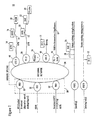
- FIG. 3 is a logical view of the home network 10 of the present invention.
- the multi-port switched hub 38 forms the center of the network connections.
- a traditional, commercially available packet switched hub is employed.
- the switched hub 38 is a combination of networked ports and ports that are direct (circuit) switched for the duration of a session.
- the direct connected ports (and systems) can be phase locked via the network (coded) clock.
- the switched hub 38 therefore comprises a relatively simple and inexpensive hub 42 and a direct circuit crossbar 44.
- the hub 42 in certain preferred embodiments, may be a commercially available device, such as Am79C981 manufactured by Advanced Micro Devices, of Sunnyvale, California. Details of the direct circuit crossbar 44 will be described later with respect to Figure 7.
- a star topology as defined by Ethernet 10/100base-T is used in conjunction with the switching hub 38.
- the switching hub 38 provides fan out to most rooms in the house 36.
- the switched hub 38 enables special treatment for the heavily asymmetric traffic, e.g., compressed digital video and internet data by directly routing these cases from transmitter to receiver.
- This traffic is thus separated from the internal network 34 and allows an overall aggregate bandwidth to be limited only by the expandability of the hub 38, although it will remain limited by the 10Mbits/s per branch.
- Use of 100base-T technology instead of 10base-T technology will uprate the network if required.
- the switching hub's direct synchronous (Manchester or block encoded) connections are used primarily for the transmission of MPEG video where a continuous, high bit rate, long duration connection is required.
- High bit rate video in compressed form can be as high as 8 Mbits/sec and is needed for live video and high action movies and sports.
- Low bit-rate video is 1.5 Mbits/sec.
- MPEG digital video is retained throughout the network 10. Conversion to real video takes place only at the display device (e.g., television 12) or the set-top electronics 40.
- Two separate direct circuits are depicted as examples in Figure 3.
- the network interface unit 32 that is coupled to an ISDN network is directly connected through the direct circuit crossbar 44 to the personal computer 20 of the local peripheral network 15.
- Another, separate direct circuit is provided by the direct circuit crossbar 44 between a different network interface unit 32 (coupled to hybrid fiber coax, for example) and the set-top electronics 40 coupled to the television 12. Those devices that are not directly connected through the direct circuit crossbar 44 remain attached to the hub 42 and are thus networked.
- An advantage of directly switched paths is that potential delays in obtaining access to the network 34 (and possibly upsetting the delicate clock reference timing carried in the MPEG stream) are avoided altogether.
- the hub 38 in certain preferred embodiments, is required to be "full-duplex aware" meaning that a directly routed path connects only a transmitter terminal "up" path only to a receive terminal “down” path.
- the path down to the transmitter and path up to the receiver are not affected by the direct circuit and would normally be attached to the network, i.e., attached to all the remaining terminal paths connected together.
- the MPEG clock recovery is performed at the network interface units 32, as described later. With the MPEG clock recovery at the network interface units 32, and the establishment of a direct circuit to the home network destination, jitter in the signal received at the destination (such as the television 12) is substantially eliminated. Direct circuit capability works well for the heavily asymmetric point to point traffic expected in the entertainment (video) home scenario.
- hybrid fiber coax For analog only services, e.g., transitional cable TV, this is not considered part of the digital network.
- mixed digital/analog services such as hybrid fiber coax (HFC) and newer forms of mixed cable TV, this is considered a transitional state and dealt with as a temporary add-on to the all digital system of the present invention.
- the signal from the hybrid fiber coax is provided directly to a set-top electronics 40 or to a network interface unit 32/set-top electronics 40 combination. Two ports are required to connect to the home network 10, one for the network interface unit 32 and one for the set-top electronics 40.
- a bypass is provided in certain preferred embodiments to link the analog signals across to the audio/video circuits of the set-top electronics 40.
- the home network 10 is controlled via hand held commander or computer keyboard to software running at the local terminals, such as the personal computers 20, or set-top electronics 40. Control software local to each home terminal manages source availability, source selection, path management by communication with the network interface units 32 and external gateways. The external network protocols are buffered in the network interface units 32 to provide a standard interface to the terminals on the home network 10.
- Figure 8 depicts one an example of a user interface. In this embodiment, the home network 10 is transparent and the user is only aware of it indirectly from the number of connected services.
- Figure 4 is a block diagram depicting a single network interface unit 32 coupled by the internal network 34 to a single set-top electronics unit 40. The remaining portions of the home network 10, including the switching hub 38, are not shown in Figure 4 for purposes of illustration and explanation.
- the network interface unit 32 has one or more network interface modules 50 that interface the network interface unit 32 to a particular external network.
- the network interface module 50 provides an interface to an external network that carries MPEG video data.
- the MPEG video data is provided to an internal network interface device 52 that prepares the data for transport over the internal network 34.
- the internal network 34 is an Ethernet network, so that the internal network interface device 52 is an Ethernet interface device.
- the architecture of the present invention assumes that for some networks a first stage demultiplexing at the network interface unit 32 is necessary to stay within a definable bandwidth limit (one stream) rather than an arbitrary bandwidth set by the construction of the incoming stream (multiple streams).
- a definable bandwidth limit one stream
- MPEG-2 MPEG-2 video
- decoding is preferably only performed at the display terminal or computer.
- the network interface module 50 buffers the home network hardware and software from the peculiarities of the attached external. network. Multiple different programs require multiple network interface crossbar connections whether from one or multiple providers. In certain embodiments, a dual module is provided with two connections to the crossbar, providing two programs received from the same external network.
- the MPEG transport chip 54 performs the MPEG clock recovery and provides the recovered 27 MHz clock and the selected program to an internal network connection 56.
- the 27 MHz clock is received by an MPEG to network synthesizer 58 and converted to a 10 MHz clock, for example, when the internal network 34 is a 10base-T Ethernet network.
- the 10 MHz clock, as well as the selected program, are provided to a conventional transceiver 60 (such as an Ethernet transceiver) connected to the internal network 34.
- the synthesizer 58 acts to lock the Ethernet clock to the recovered MPEG clock.
- the set-top electronics 40 is locked to the recovered MPEG data at 27 MHz.
- the 27 Mhz clock is regenerated from the Ethernet 10 MHz clock by another synthesizer.
- the data is received in the set-top electronics 40 by a network interface device 62 that includes a network interface 64.
- the 10 MHz clock recovered by the network interface 64 from the data stream off the network 34 is gated through gate 66 to a network to MPEG synthesizer 68. Gating is needed so that the locking function is performed only when there is a packet of data present.
- the 10 MHz clock is converted to a 27 MHz clock provided to an MPEG decoder 70 and a video decoder/encoder 72.
- the selected program is provided by the network interface 64 to the MPEG decoder 70, which decodes the MPEG data and provides it to the video decoder/encoder 72.
- the data stream is converted by the video encoder 72 to a format (e.g., NTSC or SVideo) suitable for use by a display device, such as a television.
- a format e.g., NTSC or SVideo
- the video decoder os for the case (HFC) where there may be an NTSC analog signal to digitize and merge with on-board graphics hardware.
- the network 34 in Figure 4 is depicted schematically, and it should be understood from the previous description that the video data may be placed on the network 34 through the hub 42, but that a direct circuit of the network interface unit 32 and the set-top electronics 40 through the direct circuit crossbar 44 of the network 34 is preferred to provide a jitter free transfer of video data.
- FIG 5 is a more detailed diagram of an exemplary embodiment of the network interface device 62 of the set-top electronics 40 depicted in Figure 4.
- the network interface device 62 includes the network synthesizer 68 coupled to a program logic device operating as the gating device 66.
- the network synthesizer 68 may be implemented by a commercially available chip, such as the MC145151 manufactured by Motorola.
- the program logic device 66 may be implemented by a commercially available chip, such as the MC7958, also manufactured by Motorola.
- a voltage controlled crystal oscillator 80 operates at 27 MHz and provides its signal to the program logic device 62, which gates the 10 MHz signal to the synthesizer 68 when there is a received data packet.
- the synthesizer divides down the 10 MHz and 27 MHz frequencies to a common frequency which is fed into a phase detector of the synthesizer 68.
- the output of the phase detector of the synthesizer 68 is provided as a control signal to the voltage controlled crystal oscillator 80 to adjust the local frequency up or down to lock to the incoming Ethernet frequency.
- the signal informing the program logic device 66 of the receipt of a data packet, and the 10 MHz clock, are provided by a serial interface adapter 82 serving as a receive enable.
- a commercially available product suitable for the serial interface adapter is Am7992B, manufactured by Advanced Micro Devices.
- the data stream is received through a transformer/filter 84, such as one commercially available from Pulse Engineering, the PE68026. Collision information is also received through another transformer/filter 86, which can be the same type of transformer/filter as 84.
- the received data is provided to a first network transceiver 88, such as a twisted pair Ethernet transceiver plus (Am79C100).
- the output of the first network transceiver 88 (the received data) is made available to the receive enable 82 and a controller 90.
- the controller 90 may be a commercially available product, such as the single-chip Ethernet controller Am79C970 (manufactured by Advanced Micro Devices).
- the controller 90 is coupled to a bus 92, such as a peripheral component interconnect (PCI) bus, for providing the received data from the network 34 to the MPEG decoder 70 of the set-top electronics 40.
- PCI peripheral component interconnect
- a second network transceiver 92 is coupled to the controller 90, and may be implemented by the same type of transceiver as 88.
- the second network transceiver 92 provides the transmit path for data from the controller 90 to the network 34 through the transformer/filter 84.
- Collision information is routed through transformer/filter 86 and the second transceiver 92 to the controller 90.
- FIG 6 is a more detailed diagram of the internal network connection 56, which has an MPEG to network synthesizer 58 that synthesizes the 10 MHz clock from the 27 MHz MPEG clock recovered by the MPEG transport chip 54 (see Figure 4).
- a crystal oscillator 96 is coupled to the synthesizer 58 to provide a 10 MHz signal.
- the crystal oscillator 96 is a 20 MHz oscillator, and the frequency generated by the synthesizer is 20 MHz, which is then simply divided to 10 MHz at the receiver (the set-top electronics 40).
- a commercially available synthesizer is the MC145145-2, manufactured by Motorola.
- the 10 MHz clock is provided to a microprocessor interface 98, which serves as interface for a microprocessor 100.
- the microprocessor interface 98 with the microprocessor 100, form the transceiver 60 that connects to the internal network 34 through a transformer/filter 102.
- the microprocessor interface 98 may be, for example, a MC68160 chip manufactured by Motorola, and the microprocessor may be a MC68EN360, also manufactured by Motorola.
- the transformer/filter 102 may be the same type as transformer/filters 84, 86 of Figure 5.
- the network interface unit 32 is responsible for performing external network specific interfacing, tuning demodulation, and error correction. It provides external network specific video descrambling and encryption/decryption (credit card number, user password, etc.).
- the network interface unit 32 also provides an external network specific program guide. Additionally, it performs MPEG transport demultiplexing to a single stream and MPEG reference clock recovery.
- the network interface unit provides home network Ethernet interfacing and MPEG/Ethernet clock locking. It also provides the software to support the external network and home network protocols for multiple streams and multiple users.
- the network interface unit also has the software to act as the gateway for the home network and control the buffering of data as necessary.
- the set-top electronics 40 essentially acts as an application computer with audio, video, graphic and analog television interface, in preferred embodiments.
- the set-top electronics provides the home network specific interfacing and data buffering as necessary. It provides Ethernet clock/MPEG clock locking in preferred embodiments.
- the set-top electronics 40 decodes MPEG video and audio to recover digital audio/video. It performs digital to analog conversion for audio and video, and supports commands from an infrared remote control.
- the set-top electronics 40 provides support for analog video input (NTSC). It interfaces printers, game ports, etc., and supports boot level operating system and is able to down load a full system from an external network.
- the set-top electronics 40 supports application programs and communications through the network interface units to a network provider and program video server.
- Figure 7 is a block diagram depicting in more detail an exemplary embodiment of the hub 42 and direct circuit crossbar 44 arrangement of the present invention and its connection with a network interface unit 32 and set-top electronics 40.
- the direct circuit crossbar 44 and 42 selectively provide either a direct circuit between a particular network interface unit 32 and a set-top electronics 40, or a simple network connection through the hub 42 for these units.
- only portions of the network interface unit 32 and the set-top electronics 40 are depicted, for purposes of illustration and explanation.
- the hub 42 is a relatively simple and inexpensive hub, since it does not include any sort of packet routing switch or store and forward switch. There is no intelligence that examines the traffic and dynamically switches the hub according to the transmit and receive addresses as in hubs that have packet routing switches.
- any number of directly connected pairs may be connected by the direct circuit crossbar 44, depending on the size of the crossbar 44.
- the network interface unit 32 and the set-top electronics 40 are each shown with five pin positions or connections, each of the connections being a pair. This coincides with a conventional telephone plug, the telephone RJ45, which has ten pin positions.
- the internal network 34 provides the connection between the network interface units 32, the set-top electronics 40 and the direct circuit crossbar 44.
- the internal network 34 is 10 or 100base-T Ethernet.
- a microprocessor 110 serves as the controller for the direct circuit crossbar 44 and controls the positions of the switches 108 in response to user commands that require a direct circuit to perform. For example, a user may choose to watch a movie from a video on demand service and therefore makes this selection on a hand-held remote control.
- the microprocessor 110 in response to this selection, will then change the positions of the switches 108 to establish a direct circuit between the network interface unit 32 that is connected to the external network that carries the video on demand service, and the set-top electronics 40 that is coupled to the television receiver on which the user desires to view the movie.
- switch 108a is moved to its illustrated position to connect the transmit lines of transceiver 88 of the network interface unit 32 to line 112 of the direct circuit crossbar 44.
- the transmit lines of transceiver 88 are no longer connected to the network at the Txl port of the hub 42.
- the receive lines of the transceiver 92 of the set-top electronics 40 are connected through switch 108g to the same line 112 of the direct circuit crossbar 44.
- the direct circuit established by the direct circuit crossbar 44 provides an excellent pathway for data from the network interface unit 32 to the set-top electronics 40, it may occur that not all of the data coming into the network interface unit 32 is meant for the set-top electronics 40. For example, it is possible that e-mail is received over this particular network interface unit 32, and the homeowner wants e-mail to be directed to a personal computer, and not to a television. However, there is no connection to the network 34 due to the direct circuit once a direct circuit is established.
- the set-top electronics 40 examines the addresses of the data packets it receives and performs a routing function for data that is not meant for this set-top electronics 40. The data is rerouted by the set-top electronics 40 onto the network 34 through the hub 42. This re-routing by the end point connection (the set-top electronics 40 in this example) avoids the need for the system to use an expensive and complicated router.
- the set-top electronics 40 has a microprocessor 120 and associated memory 122 to identify and route the data packets back to the network 34.
- the direct circuit between the network interface unit 32 and the set-top electronics 40 provides a jitter-free connection for video data, but the re-routing of other data into the network 34 through the hub allows more than one type of data to be carried into the home by the network interface unit 32.
- collision detection is required by the set-top electronics 40 to allow it to transmit to the hub 42.
- the set-top electronics 40 needs to learn of collisions and re-transmit the data to the network 34 if such collisions occur.
- the network interface unit 32 can be set, in certain embodiments, to disable collisions because they cannot occur on the direct circuit. However, in certain embodiments, in both the network interface unit port and the set-top electronics port (to the network 34 through the crossbar 44), the same collision pair is included for convenience.
- one of the five pairs of wires is available to provide picture-in-picture capability for the system.
- the network interface unit 32 may provide a second stream of data through another transceiver 88a over a second pair of transmit wires onto a separate crossbar connection line 114.
- the set-top electronics 40 which has another transceiver 88a also connected to line 114, receives this second stream of data through the direct circuit to provide a picture-in-picture on a television screen.
- both pictures may be provided without jitter by separate direct circuits.
- the crossbar switches 108 are implemented by an analog MOS array of transistors, controlled in response to signals from the controller 110. This is exemplary only, however, as other embodiments employ switches of different design, as appreciated by one of ordinary skill in the art.
- the hub 42 is described as connected to the internal network.
- the hub 42 may also be logically considered as part of the internal network, or even forming the network, with the remaining wiring forming means for attaching end terminals to the hub 42.
- the logical distinctions depicted and described in the present specification are exemplary only.
- the separation of the network interface unit and the set-top electronics according to the present invention provides a relatively inexpensive connection of a multitude of devices to each other within the home, and to the outside world.
Claims (9)
- Multimedia-Netzwerk-Architektur (10) für eine Struktur, umfassend:wobei der Verteiler (42) und die Direkt-Schaltungskreuzschiene (44) so konfiguriert sind, um eine Netzwerk-Verbindung zwischen der Netzwerk-Schnittstellen-Einheit (32) und dem Aufsatzkasten (40) zu schaffen, und weiterhin so konfigurierbar sind, um selektiv eine direkte Schaltungsverbindung zwischen der Netzwerk-Schnittstellen-Einheit (32) und dem Aufsatzkasten (40) zu schaffen.einen Port (30) eines externen Netzwerks, der mindestens eine Netzwerk-Schnittstellen-Einheit (32) besitzt, die mit einem einer Mehrzahl von Netzwerken, angeordnet extern der Struktur, gekoppelt ist;ein internes Netzwerk (34) innerhalb der Struktur mit einem Verteiler (42) und einer Direkt-Schaltungskreuzschiene (44), wobei das interne Netzwerk (34) ein digitales Netzwerk ist, das so konfiguriert ist, um Daten bei einer bekannten Frequenz zu führen, und mit dem Port (30) eines externen Netzwerks gekoppelt ist; undmindestens einen Aufsatzkasten (40), gekoppelt mit dem internen Netzwerk (34), und so konfiguriert, um die Daten von dem internen Netzwerk (34) aufzunehmen,
- Architektur (10) nach Anspruch 1, wobei der Port (30) des externen Netzwerks eine Mehrzahl von Netzwerk-Schnittstellen-Einheiten (32) besitzt, wobei die Netzwerk-Schnittstellen-Einheiten (32) jeweils mit unterschiedlichen, externen Netzwerken gekoppelt sind.
- Architektur (10) nach Anspruch 2, wobei das interne Netzwerk (34) ein Ethernet-Netzwerk ist.
- Architektur (10) nach Anspruch 2, wobei eine Mehrzahl von Aufsatzkästen (40) mit dem internen Netzwerk (34) gekoppelt ist.
- Architektur (10) nach Ansruch 3, wobei mindestens eine einer Mehrzahl der Verarbeitungs-Vorrichtungen (20) mit dem Ethernet-Netzwerk gekoppelt ist.
- Architektur (10) nach Anspruch 5, wobei mindestens eine einer Mehrzahl von peripheren Vorrichtungen (12, 14, 16, 18, 22 und 24) mit dem Ethernet-Netzwerk gekoppelt ist.
- Architektur (10) nach Anspruch 6, wobei das Ethernet-Netzwerk ein 10baseT Ethernet ist.
- Architektur (10) nach Anspruch 6, wobei das Ethernet-Netzwerk ein 100baseT Ethernet ist.
- Architektur (10) nach Anspruch 1, das weiterhin eine Koaxial-Verkabelung innerhalb der Struktur aufweist und mit einer Koaxial-Verkabelung extern zu der Struktur, die audiovisuelle Informationen führt, gekoppelt ist.
Applications Claiming Priority (3)
| Application Number | Priority Date | Filing Date | Title |
|---|---|---|---|
| US561758 | 1990-08-02 | ||
| US56175895A | 1995-11-22 | 1995-11-22 | |
| PCT/US1996/018798 WO1997019538A1 (en) | 1995-11-22 | 1996-11-21 | Home multimedia network architecture |
Publications (2)
| Publication Number | Publication Date |
|---|---|
| EP0862826A1 EP0862826A1 (de) | 1998-09-09 |
| EP0862826B1 true EP0862826B1 (de) | 2002-04-03 |
Family
ID=24243327
Family Applications (1)
| Application Number | Title | Priority Date | Filing Date |
|---|---|---|---|
| EP96942050A Expired - Lifetime EP0862826B1 (de) | 1995-11-22 | 1996-11-21 | Architektur eines heim-multimedia-netzwerkes |
Country Status (10)
| Country | Link |
|---|---|
| US (1) | US5940387A (de) |
| EP (1) | EP0862826B1 (de) |
| JP (3) | JP3785579B2 (de) |
| KR (1) | KR100387709B1 (de) |
| CN (1) | CN1100422C (de) |
| AT (1) | ATE215763T1 (de) |
| CA (1) | CA2238394C (de) |
| DE (1) | DE69620439T2 (de) |
| IL (1) | IL124606A (de) |
| WO (1) | WO1997019538A1 (de) |
Families Citing this family (221)
| Publication number | Priority date | Publication date | Assignee | Title |
|---|---|---|---|---|
| US8352400B2 (en) | 1991-12-23 | 2013-01-08 | Hoffberg Steven M | Adaptive pattern recognition based controller apparatus and method and human-factored interface therefore |
| US7006881B1 (en) * | 1991-12-23 | 2006-02-28 | Steven Hoffberg | Media recording device with remote graphic user interface |
| US10361802B1 (en) | 1999-02-01 | 2019-07-23 | Blanding Hovenweep, Llc | Adaptive pattern recognition based control system and method |
| JP3812681B2 (ja) * | 1994-10-27 | 2006-08-23 | インデックス システムズ, インコーポレイティド | ビデオ信号中のレコーダ・プログラミング・データをダウンロードする装置及び方法 |
| US5886732A (en) * | 1995-11-22 | 1999-03-23 | Samsung Information Systems America | Set-top electronics and network interface unit arrangement |
| US6622304B1 (en) | 1996-09-09 | 2003-09-16 | Thomas W. Carhart | Interface system for computing apparatus and communications stations |
| US6282714B1 (en) | 1997-01-31 | 2001-08-28 | Sharewave, Inc. | Digital wireless home computer system |
| US20030192053A1 (en) * | 1997-02-19 | 2003-10-09 | Next Level Communications, Inc. | Method and apparatus for transmitting wireless signals over media |
| US20040083493A1 (en) * | 1997-02-19 | 2004-04-29 | Next Level Communications, Inc. | Transmitting caller ID within a digital stream |
| JP4301530B2 (ja) * | 1997-03-12 | 2009-07-22 | ソニー株式会社 | 情報処理装置および方法 |
| WO1998059478A1 (en) * | 1997-06-25 | 1998-12-30 | Samsung Electronics Co., Ltd. | Programming tool for home networks |
| KR100268498B1 (ko) * | 1997-06-26 | 2000-10-16 | 윤종용 | 셋탑박스를이용한pc통신및인터넷서비스장치와그방법 |
| FR2766039B1 (fr) * | 1997-07-11 | 1999-08-13 | France Telecom | Dispositif interface de communication entre une installation terminale d'abonne d'un reseau externe et un reseau interne |
| US6938073B1 (en) * | 1997-11-14 | 2005-08-30 | Yahoo! Inc. | Method and apparatus for re-formatting web pages |
| US6216157B1 (en) * | 1997-11-14 | 2001-04-10 | Yahoo! Inc. | Method and apparatus for a client-server system with heterogeneous clients |
| US6108696A (en) * | 1997-11-14 | 2000-08-22 | Online Anywhere | Method and apparatus to connect a general purpose computer to a special purpose system |
| US6510152B1 (en) * | 1997-12-31 | 2003-01-21 | At&T Corp. | Coaxial cable/twisted pair fed, integrated residence gateway controlled, set-top box |
| US6999945B1 (en) * | 1998-01-29 | 2006-02-14 | Automated Business Companies | Multiple customer and multiple location PC service provider system |
| US20020059468A1 (en) | 1999-11-18 | 2002-05-16 | Freeny Charles C. | Split personal computer system |
| US6243743B1 (en) * | 1998-01-29 | 2001-06-05 | Automated Business Companies | Split personal computer system |
| JP4277142B2 (ja) * | 1998-03-26 | 2009-06-10 | ソニー株式会社 | 受信装置 |
| IL139408A0 (en) * | 1998-05-07 | 2001-11-25 | Samsung Electronics Co Ltd | Method and apparatus for user and device command and control in a network |
| US7043532B1 (en) | 1998-05-07 | 2006-05-09 | Samsung Electronics Co., Ltd. | Method and apparatus for universally accessible command and control information in a network |
| US6233611B1 (en) * | 1998-05-08 | 2001-05-15 | Sony Corporation | Media manager for controlling autonomous media devices within a network environment and managing the flow and format of data between the devices |
| EP0964558A1 (de) * | 1998-06-08 | 1999-12-15 | THOMSON multimedia | Zugriffsverfahren auf Internet-Anwedungen von Hausnetzwerkgeräten |
| US6185737B1 (en) * | 1998-06-30 | 2001-02-06 | Sun Microsystems, Inc. | Method and apparatus for providing multi media network interface |
| JP2995177B1 (ja) * | 1998-07-10 | 1999-12-27 | 株式会社ディジタル・ビジョン・ラボラトリーズ | ストリーム配信システム |
| US6108331A (en) * | 1998-07-10 | 2000-08-22 | Upstate Systems Tec, Inc. | Single medium wiring scheme for multiple signal distribution in building and access port therefor |
| CN1867068A (zh) | 1998-07-14 | 2006-11-22 | 联合视频制品公司 | 交互式电视节目导视系统及其方法 |
| PT1986425E (pt) | 1998-07-17 | 2014-07-24 | United Video Properties Inc | Sistema de guia de programas de televisão interactivo que tem múltiplos dispositivos dentro de uma zona habitacional |
| AR020608A1 (es) | 1998-07-17 | 2002-05-22 | United Video Properties Inc | Un metodo y una disposicion para suministrar a un usuario acceso remoto a una guia de programacion interactiva por un enlace de acceso remoto |
| US6505348B1 (en) | 1998-07-29 | 2003-01-07 | Starsight Telecast, Inc. | Multiple interactive electronic program guide system and methods |
| US20010005908A1 (en) * | 1998-09-28 | 2001-06-28 | Hodge Winston W. | Method for buffering video, data and voice signals using a common shared bus |
| US20060069657A1 (en) * | 1998-10-01 | 2006-03-30 | Freeny Charles C Jr | Multiple customer and multiple location PC service provider system |
| US7107322B1 (en) | 1998-10-01 | 2006-09-12 | Automated Business Companies | Master operating software system |
| US6259745B1 (en) * | 1998-10-30 | 2001-07-10 | Broadcom Corporation | Integrated Gigabit Ethernet transmitter architecture |
| US6470053B1 (en) * | 1998-10-30 | 2002-10-22 | Compaq Information Technologies Group, L.P. | Methods and arrangements for transmitting data over twisted pair wire using RF modulation techniques |
| US7904187B2 (en) | 1999-02-01 | 2011-03-08 | Hoffberg Steven M | Internet appliance system and method |
| GB2350036A (en) * | 1999-03-03 | 2000-11-15 | Samsung Inf Syst America | Multimedia home network architecture |
| AU3624600A (en) * | 1999-03-12 | 2000-09-28 | Lanart Corporation | Automatic crossover system for a media dependent interface with hysteresis |
| JP2000278654A (ja) * | 1999-03-26 | 2000-10-06 | Sony Corp | 音声及び/または映像信号の伝送システム、その送信装置、及びその受信装置 |
| JP3417872B2 (ja) * | 1999-04-07 | 2003-06-16 | 日本電気株式会社 | 交換方法 |
| US7213061B1 (en) * | 1999-04-29 | 2007-05-01 | Amx Llc | Internet control system and method |
| US6801507B1 (en) | 1999-07-27 | 2004-10-05 | Samsung Electronics Co., Ltd. | Device discovery and configuration in a home network |
| US7490293B1 (en) | 1999-07-27 | 2009-02-10 | Samsung Electronics Co., Ltd. | Device discovery and control in a bridged home network |
| US7610559B1 (en) | 1999-07-27 | 2009-10-27 | Samsung Electronics Co., Ltd. | Device customized home network top-level information architecture |
| US8032833B1 (en) | 1999-07-27 | 2011-10-04 | Samsung Electronics Co., Ltd. | Home network device information architecture |
| US6690657B1 (en) | 2000-02-25 | 2004-02-10 | Berkeley Concept Research Corporation | Multichannel distributed wireless repeater network |
| US7200683B1 (en) | 1999-08-17 | 2007-04-03 | Samsung Electronics, Co., Ltd. | Device communication and control in a home network connected to an external network |
| US7633963B1 (en) * | 1999-09-22 | 2009-12-15 | Plantronics, Inc. | Accessory interface bus for telephone headset adapter |
| WO2001033784A1 (fr) * | 1999-11-01 | 2001-05-10 | Matsushita Electric Industrial Co., Ltd. | Procede et appareil de transmission d'informations |
| US20020056116A1 (en) * | 2000-03-29 | 2002-05-09 | Wesley Smith | Home bus computer system and method |
| US7149816B1 (en) * | 2000-05-16 | 2006-12-12 | Lucent Technologies Inc. | System and method for peer-level communication with a network interface card |
| DE10025732A1 (de) * | 2000-05-25 | 2002-01-31 | Rinn Frank | Programmierbarer, speicherfähiger Übertragungsleitungs-Umschalter zur optimierten Nutzung von Daten- und Informationsdienstleistungen an verschiedenen Kabeltyen |
| US7068596B1 (en) | 2000-07-07 | 2006-06-27 | Nevco Technology, Inc. | Interactive data transmission system having staged servers |
| US7349967B2 (en) | 2000-07-21 | 2008-03-25 | Samsung Electronics Co., Ltd. | Architecture for home network on world wide web with private-public IP address/URL mapping |
| KR20160042161A (ko) | 2000-10-11 | 2016-04-18 | 로비 가이드스, 인크. | 매체 콘텐츠 배달 시스템 및 방법 |
| US8127326B2 (en) | 2000-11-14 | 2012-02-28 | Claussen Paul J | Proximity detection using wireless connectivity in a communications system |
| EP1334617B1 (de) | 2000-11-14 | 2015-04-01 | Cisco Technology, Inc. | Vernetzte bereitstellung von teilnehmerfernsehen |
| US7170405B2 (en) * | 2000-12-26 | 2007-01-30 | General Electric Company | Method and apparatus for interfacing a power line carrier and an appliance |
| US20030046377A1 (en) * | 2000-12-27 | 2003-03-06 | Wolfgang Daum | Method and apparatus for appliance service diagnostics |
| AU2002229957A1 (en) * | 2001-02-09 | 2002-08-28 | Quadriga Technology Limited | Method and apparatus for distributing data |
| US20030075983A1 (en) * | 2001-05-03 | 2003-04-24 | Mitsubishi Digital Electronics America, Inc. | Control system and user interface for network of input devices |
| US20020188762A1 (en) * | 2001-05-04 | 2002-12-12 | Tomassetti Stephen Robert | Data structure for an entertainment and communications network |
| US20020188752A1 (en) * | 2001-05-04 | 2002-12-12 | Tomassetti Stephen Robert | Control messaging for an entertainment and communications network |
| US6907458B2 (en) * | 2001-05-04 | 2005-06-14 | M&S Systems, L.P. | Digital multi-room, multi-source entertainment and communications network |
| US6934300B2 (en) * | 2001-05-04 | 2005-08-23 | M&S Systems, L.P. | Initialization method for an entertainment and communications network |
| US8291457B2 (en) | 2001-05-24 | 2012-10-16 | Vixs Systems, Inc. | Channel selection in a multimedia system |
| US20090031419A1 (en) | 2001-05-24 | 2009-01-29 | Indra Laksono | Multimedia system and server and methods for use therewith |
| US20030005460A1 (en) | 2001-07-01 | 2003-01-02 | David Bartholomew | Method and system for a low cost wireless telephone link for a set top box |
| US7102691B2 (en) * | 2001-08-08 | 2006-09-05 | Matsushita Electric Industrial Co., Ltd. | Method and apparatus for remote use of personal computer |
| US7142560B2 (en) * | 2001-08-14 | 2006-11-28 | Sharp Laboratories Of America, Inc. | System and method for virtual multiline telephony in a home-network telephone |
| FR2832888B1 (fr) * | 2001-11-23 | 2004-02-27 | France Telecom | Systeme de gestion d'applications dediees a des appareils connectes a un reseau, procede de gestion d'applications, terminal d'acces, serveur d'applications et appareil pour un tel systeme |
| US6658091B1 (en) | 2002-02-01 | 2003-12-02 | @Security Broadband Corp. | LIfestyle multimedia security system |
| EP1361714A1 (de) * | 2002-05-10 | 2003-11-12 | MAYAH Communications GMBH | Verfahren, System und Vorrichtungen zur Übertragung von Audio- und/oder Videosignalen zwischen synchronen und asynchronen Netzwerken und zur Minimierung der Zeitverzögerung in solchen Netzwerken |
| US20030227485A1 (en) * | 2002-06-11 | 2003-12-11 | Krakirian Haig H. | Method and apparatus for controlling and receiving data from connected devices |
| US6975364B2 (en) * | 2002-06-13 | 2005-12-13 | Hui-Lin Lin | Radio television and frequency modulation monitor transmitting receiving control apparatus |
| US20040218688A1 (en) * | 2002-06-21 | 2004-11-04 | John Santhoff | Ultra-wideband communication through a power grid |
| US7099368B2 (en) | 2002-06-21 | 2006-08-29 | Pulse-Link, Inc. | Ultra-wideband communication through a wire medium |
| US6782048B2 (en) | 2002-06-21 | 2004-08-24 | Pulse-Link, Inc. | Ultra-wideband communication through a wired network |
| US7167525B2 (en) * | 2002-06-21 | 2007-01-23 | Pulse-Link, Inc. | Ultra-wideband communication through twisted-pair wire media |
| US20040156446A1 (en) * | 2002-06-21 | 2004-08-12 | John Santhoff | Optimization of ultra-wideband communication through a wire medium |
| US7027483B2 (en) * | 2002-06-21 | 2006-04-11 | Pulse-Link, Inc. | Ultra-wideband communication through local power lines |
| US20040139467A1 (en) * | 2002-06-26 | 2004-07-15 | Michael Rogerson | Aircraft communication distribution system |
| DE10228605A1 (de) * | 2002-06-26 | 2004-01-15 | Deutsche Thomson-Brandt Gmbh | Modul zur Integration in einem Heimnetzwerk |
| US6895034B2 (en) | 2002-07-02 | 2005-05-17 | Pulse-Link, Inc. | Ultra-wideband pulse generation system and method |
| US7340509B2 (en) | 2002-07-18 | 2008-03-04 | General Electric Company | Reconfigurable appliance control system |
| US7516470B2 (en) | 2002-08-02 | 2009-04-07 | Cisco Technology, Inc. | Locally-updated interactive program guide |
| KR100859408B1 (ko) * | 2002-09-28 | 2008-09-22 | 주식회사 케이티 | 홈오토 통신을 위한 디지털 가입자망 단말기 및 디지털 가입자망 접속장치 |
| US7908625B2 (en) | 2002-10-02 | 2011-03-15 | Robertson Neil C | Networked multimedia system |
| US20040068753A1 (en) * | 2002-10-02 | 2004-04-08 | Robertson Neil C. | Video transmission systems and methods for a home network |
| US7360235B2 (en) | 2002-10-04 | 2008-04-15 | Scientific-Atlanta, Inc. | Systems and methods for operating a peripheral record/playback device in a networked multimedia system |
| US8046806B2 (en) | 2002-10-04 | 2011-10-25 | Wall William E | Multiroom point of deployment module |
| US7545935B2 (en) | 2002-10-04 | 2009-06-09 | Scientific-Atlanta, Inc. | Networked multimedia overlay system |
| US6836226B2 (en) * | 2002-11-12 | 2004-12-28 | Pulse-Link, Inc. | Ultra-wideband pulse modulation system and method |
| US7487532B2 (en) | 2003-01-15 | 2009-02-03 | Cisco Technology, Inc. | Optimization of a full duplex wideband communications system |
| US8094640B2 (en) | 2003-01-15 | 2012-01-10 | Robertson Neil C | Full duplex wideband communications system for a local coaxial network |
| US7493646B2 (en) | 2003-01-30 | 2009-02-17 | United Video Properties, Inc. | Interactive television systems with digital video recording and adjustable reminders |
| US7433740B2 (en) * | 2003-03-05 | 2008-10-07 | Colorado Vnet, Llc | CAN communication for building automation systems |
| US20040176877A1 (en) * | 2003-03-05 | 2004-09-09 | Scott Hesse | Building automation system and method |
| US6927546B2 (en) * | 2003-04-28 | 2005-08-09 | Colorado Vnet, Llc | Load control system and method |
| US20040218591A1 (en) * | 2003-04-29 | 2004-11-04 | Craig Ogawa | Bridge apparatus and methods of operation |
| US7369660B1 (en) | 2003-05-20 | 2008-05-06 | The Directv Group, Inc. | Methods and apparatus for distributing digital content |
| US7454120B2 (en) | 2003-07-02 | 2008-11-18 | Macrovision Corporation | Methods and apparatus for client aggregation of television programming in a networked personal video recording system |
| US8438601B2 (en) | 2003-07-02 | 2013-05-07 | Rovi Solutions Corporation | Resource management for a networked personal video recording system |
| US7472203B2 (en) * | 2003-07-30 | 2008-12-30 | Colorado Vnet, Llc | Global and local command circuits for network devices |
| US20050049730A1 (en) * | 2003-08-29 | 2005-03-03 | Adamson Hugh P. | Keypad for building automation |
| US20050049726A1 (en) * | 2003-08-29 | 2005-03-03 | Adamson Hugh P. | Input device for building automation |
| US8528015B2 (en) * | 2003-11-06 | 2013-09-03 | Aptiv Digital, Inc. | Resource sharing system of set-top boxes |
| US7171506B2 (en) * | 2003-11-17 | 2007-01-30 | Sony Corporation | Plural interfaces in home network with first component having a first host bus width and second component having second bus width |
| IL159838A0 (en) | 2004-01-13 | 2004-06-20 | Yehuda Binder | Information device |
| US10382452B1 (en) | 2007-06-12 | 2019-08-13 | Icontrol Networks, Inc. | Communication protocols in integrated systems |
| US11343380B2 (en) | 2004-03-16 | 2022-05-24 | Icontrol Networks, Inc. | Premises system automation |
| US9191228B2 (en) | 2005-03-16 | 2015-11-17 | Icontrol Networks, Inc. | Cross-client sensor user interface in an integrated security network |
| US20160065414A1 (en) | 2013-06-27 | 2016-03-03 | Ken Sundermeyer | Control system user interface |
| US11316958B2 (en) | 2008-08-11 | 2022-04-26 | Icontrol Networks, Inc. | Virtual device systems and methods |
| US9729342B2 (en) | 2010-12-20 | 2017-08-08 | Icontrol Networks, Inc. | Defining and implementing sensor triggered response rules |
| US10237237B2 (en) | 2007-06-12 | 2019-03-19 | Icontrol Networks, Inc. | Communication protocols in integrated systems |
| US11811845B2 (en) | 2004-03-16 | 2023-11-07 | Icontrol Networks, Inc. | Communication protocols over internet protocol (IP) networks |
| US10721087B2 (en) | 2005-03-16 | 2020-07-21 | Icontrol Networks, Inc. | Method for networked touchscreen with integrated interfaces |
| US11113950B2 (en) | 2005-03-16 | 2021-09-07 | Icontrol Networks, Inc. | Gateway integrated with premises security system |
| US10339791B2 (en) | 2007-06-12 | 2019-07-02 | Icontrol Networks, Inc. | Security network integrated with premise security system |
| US10156959B2 (en) | 2005-03-16 | 2018-12-18 | Icontrol Networks, Inc. | Cross-client sensor user interface in an integrated security network |
| US7711796B2 (en) | 2006-06-12 | 2010-05-04 | Icontrol Networks, Inc. | Gateway registry methods and systems |
| US20090077623A1 (en) | 2005-03-16 | 2009-03-19 | Marc Baum | Security Network Integrating Security System and Network Devices |
| US11582065B2 (en) | 2007-06-12 | 2023-02-14 | Icontrol Networks, Inc. | Systems and methods for device communication |
| US9141276B2 (en) | 2005-03-16 | 2015-09-22 | Icontrol Networks, Inc. | Integrated interface for mobile device |
| US11677577B2 (en) | 2004-03-16 | 2023-06-13 | Icontrol Networks, Inc. | Premises system management using status signal |
| US8963713B2 (en) | 2005-03-16 | 2015-02-24 | Icontrol Networks, Inc. | Integrated security network with security alarm signaling system |
| US8635350B2 (en) | 2006-06-12 | 2014-01-21 | Icontrol Networks, Inc. | IP device discovery systems and methods |
| US11244545B2 (en) | 2004-03-16 | 2022-02-08 | Icontrol Networks, Inc. | Cross-client sensor user interface in an integrated security network |
| US10522026B2 (en) | 2008-08-11 | 2019-12-31 | Icontrol Networks, Inc. | Automation system user interface with three-dimensional display |
| US8988221B2 (en) | 2005-03-16 | 2015-03-24 | Icontrol Networks, Inc. | Integrated security system with parallel processing architecture |
| US10444964B2 (en) | 2007-06-12 | 2019-10-15 | Icontrol Networks, Inc. | Control system user interface |
| US11277465B2 (en) | 2004-03-16 | 2022-03-15 | Icontrol Networks, Inc. | Generating risk profile using data of home monitoring and security system |
| US11916870B2 (en) | 2004-03-16 | 2024-02-27 | Icontrol Networks, Inc. | Gateway registry methods and systems |
| US10375253B2 (en) | 2008-08-25 | 2019-08-06 | Icontrol Networks, Inc. | Security system with networked touchscreen and gateway |
| US10142392B2 (en) | 2007-01-24 | 2018-11-27 | Icontrol Networks, Inc. | Methods and systems for improved system performance |
| US20170118037A1 (en) | 2008-08-11 | 2017-04-27 | Icontrol Networks, Inc. | Integrated cloud system for premises automation |
| US10313303B2 (en) | 2007-06-12 | 2019-06-04 | Icontrol Networks, Inc. | Forming a security network including integrated security system components and network devices |
| AU2005223267B2 (en) | 2004-03-16 | 2010-12-09 | Icontrol Networks, Inc. | Premises management system |
| US9609003B1 (en) | 2007-06-12 | 2017-03-28 | Icontrol Networks, Inc. | Generating risk profile using data of home monitoring and security system |
| US10200504B2 (en) | 2007-06-12 | 2019-02-05 | Icontrol Networks, Inc. | Communication protocols over internet protocol (IP) networks |
| US11368429B2 (en) | 2004-03-16 | 2022-06-21 | Icontrol Networks, Inc. | Premises management configuration and control |
| US11489812B2 (en) | 2004-03-16 | 2022-11-01 | Icontrol Networks, Inc. | Forming a security network including integrated security system components and network devices |
| US9531593B2 (en) | 2007-06-12 | 2016-12-27 | Icontrol Networks, Inc. | Takeover processes in security network integrated with premise security system |
| US11159484B2 (en) | 2004-03-16 | 2021-10-26 | Icontrol Networks, Inc. | Forming a security network including integrated security system components and network devices |
| US11201755B2 (en) | 2004-03-16 | 2021-12-14 | Icontrol Networks, Inc. | Premises system management using status signal |
| EP1815683A2 (de) * | 2004-04-16 | 2007-08-08 | Digital Accelerator Corporation | Verfahren und vorrichtung zum abliefern von verbraucher-unterhaltungsdiensten, auf die über ein ip-netzwerk zugegriffen wird |
| US8543723B2 (en) * | 2004-07-27 | 2013-09-24 | Sony Corporation | Home network system with transmission error recovery |
| JP4617894B2 (ja) * | 2005-01-18 | 2011-01-26 | 船井電機株式会社 | 入力切替え装置およびテレビジョン装置 |
| US9306809B2 (en) | 2007-06-12 | 2016-04-05 | Icontrol Networks, Inc. | Security system with networked touchscreen |
| US20110128378A1 (en) | 2005-03-16 | 2011-06-02 | Reza Raji | Modular Electronic Display Platform |
| US20170180198A1 (en) | 2008-08-11 | 2017-06-22 | Marc Baum | Forming a security network including integrated security system components |
| US10999254B2 (en) | 2005-03-16 | 2021-05-04 | Icontrol Networks, Inc. | System for data routing in networks |
| US11700142B2 (en) | 2005-03-16 | 2023-07-11 | Icontrol Networks, Inc. | Security network integrating security system and network devices |
| US11496568B2 (en) | 2005-03-16 | 2022-11-08 | Icontrol Networks, Inc. | Security system with networked touchscreen |
| US20120324566A1 (en) | 2005-03-16 | 2012-12-20 | Marc Baum | Takeover Processes In Security Network Integrated With Premise Security System |
| US11615697B2 (en) | 2005-03-16 | 2023-03-28 | Icontrol Networks, Inc. | Premise management systems and methods |
| US20150054947A1 (en) * | 2005-03-16 | 2015-02-26 | Paul J. Dawes | Device for data routing in networks |
| EP1737161A1 (de) | 2005-06-20 | 2006-12-27 | Thomson Telecom Belgium | Vorrichtung und Verfahren zur Verwaltung zwei verschiedener Typen von Vorrichtungen |
| CA2621713C (en) | 2005-09-07 | 2016-01-26 | Amx Llc | Method and computer program for device configuration |
| US7876998B2 (en) | 2005-10-05 | 2011-01-25 | Wall William E | DVD playback over multi-room by copying to HDD |
| US20070089158A1 (en) * | 2005-10-18 | 2007-04-19 | Clark Christopher M | Apparatus and method for providing access to associated data related to primary media data |
| US20080288600A1 (en) * | 2005-10-18 | 2008-11-20 | Clark Christopher M | Apparatus and method for providing access to associated data related to primary media data via email |
| US8582946B2 (en) | 2005-11-04 | 2013-11-12 | Rovi Guides, Inc. | Systems and methods for recording programs using a network recording device as supplemental storage |
| US7396306B2 (en) * | 2005-11-21 | 2008-07-08 | General Motors Corporation | Multiplexed control system and method for an electrically variable hybrid transmission |
| US10079839B1 (en) | 2007-06-12 | 2018-09-18 | Icontrol Networks, Inc. | Activation of gateway device |
| KR100772412B1 (ko) * | 2006-07-18 | 2007-11-01 | 삼성전자주식회사 | 홈 컨트롤 네트워크 제어 장치 및 방법 |
| KR100819582B1 (ko) * | 2006-08-14 | 2008-04-04 | 엘지전자 주식회사 | 네트워크 어댑터 |
| KR100779362B1 (ko) * | 2006-08-21 | 2007-11-23 | 김도형 | 홈 미디어 센터 |
| KR100885444B1 (ko) * | 2006-10-20 | 2009-02-24 | 엘지전자 주식회사 | 네트워크에서 디바이스의 출력을 제어하는 방법 |
| US10338694B2 (en) * | 2007-01-22 | 2019-07-02 | Sony Corporation | Multiple focus control |
| US11706279B2 (en) | 2007-01-24 | 2023-07-18 | Icontrol Networks, Inc. | Methods and systems for data communication |
| US7633385B2 (en) | 2007-02-28 | 2009-12-15 | Ucontrol, Inc. | Method and system for communicating with and controlling an alarm system from a remote server |
| US20080219326A1 (en) * | 2007-03-09 | 2008-09-11 | John Santhoff | Wireless multimedia link |
| US8418206B2 (en) | 2007-03-22 | 2013-04-09 | United Video Properties, Inc. | User defined rules for assigning destinations of content |
| US20080262968A1 (en) * | 2007-03-26 | 2008-10-23 | Infosys Technologies Ltd. | Software licensing control via mobile devices |
| US8451986B2 (en) | 2007-04-23 | 2013-05-28 | Icontrol Networks, Inc. | Method and system for automatically providing alternate network access for telecommunications |
| US11089122B2 (en) | 2007-06-12 | 2021-08-10 | Icontrol Networks, Inc. | Controlling data routing among networks |
| US10498830B2 (en) | 2007-06-12 | 2019-12-03 | Icontrol Networks, Inc. | Wi-Fi-to-serial encapsulation in systems |
| US10423309B2 (en) | 2007-06-12 | 2019-09-24 | Icontrol Networks, Inc. | Device integration framework |
| US11646907B2 (en) | 2007-06-12 | 2023-05-09 | Icontrol Networks, Inc. | Communication protocols in integrated systems |
| US11212192B2 (en) | 2007-06-12 | 2021-12-28 | Icontrol Networks, Inc. | Communication protocols in integrated systems |
| US11218878B2 (en) | 2007-06-12 | 2022-01-04 | Icontrol Networks, Inc. | Communication protocols in integrated systems |
| US10523689B2 (en) | 2007-06-12 | 2019-12-31 | Icontrol Networks, Inc. | Communication protocols over internet protocol (IP) networks |
| US11423756B2 (en) | 2007-06-12 | 2022-08-23 | Icontrol Networks, Inc. | Communication protocols in integrated systems |
| US11316753B2 (en) | 2007-06-12 | 2022-04-26 | Icontrol Networks, Inc. | Communication protocols in integrated systems |
| US10389736B2 (en) | 2007-06-12 | 2019-08-20 | Icontrol Networks, Inc. | Communication protocols in integrated systems |
| US10616075B2 (en) | 2007-06-12 | 2020-04-07 | Icontrol Networks, Inc. | Communication protocols in integrated systems |
| US10051078B2 (en) | 2007-06-12 | 2018-08-14 | Icontrol Networks, Inc. | WiFi-to-serial encapsulation in systems |
| US11237714B2 (en) | 2007-06-12 | 2022-02-01 | Control Networks, Inc. | Control system user interface |
| US10666523B2 (en) | 2007-06-12 | 2020-05-26 | Icontrol Networks, Inc. | Communication protocols in integrated systems |
| US11601810B2 (en) | 2007-06-12 | 2023-03-07 | Icontrol Networks, Inc. | Communication protocols in integrated systems |
| US8590028B2 (en) | 2007-07-09 | 2013-11-19 | Infosys Limited | Content licensing and conditional access using a mobile device |
| US10223903B2 (en) | 2010-09-28 | 2019-03-05 | Icontrol Networks, Inc. | Integrated security system with parallel processing architecture |
| US11831462B2 (en) | 2007-08-24 | 2023-11-28 | Icontrol Networks, Inc. | Controlling data routing in premises management systems |
| US20090247006A1 (en) * | 2008-01-22 | 2009-10-01 | Wi3, Inc., New York | Network access point having interchangeable cartridges |
| US11916928B2 (en) | 2008-01-24 | 2024-02-27 | Icontrol Networks, Inc. | Communication protocols over internet protocol (IP) networks |
| US8601526B2 (en) | 2008-06-13 | 2013-12-03 | United Video Properties, Inc. | Systems and methods for displaying media content and media guidance information |
| US20170185278A1 (en) | 2008-08-11 | 2017-06-29 | Icontrol Networks, Inc. | Automation system user interface |
| US11729255B2 (en) | 2008-08-11 | 2023-08-15 | Icontrol Networks, Inc. | Integrated cloud system with lightweight gateway for premises automation |
| US11258625B2 (en) | 2008-08-11 | 2022-02-22 | Icontrol Networks, Inc. | Mobile premises automation platform |
| US11758026B2 (en) | 2008-08-11 | 2023-09-12 | Icontrol Networks, Inc. | Virtual device systems and methods |
| US11792036B2 (en) | 2008-08-11 | 2023-10-17 | Icontrol Networks, Inc. | Mobile premises automation platform |
| US10530839B2 (en) | 2008-08-11 | 2020-01-07 | Icontrol Networks, Inc. | Integrated cloud system with lightweight gateway for premises automation |
| EP2161901A1 (de) * | 2008-09-04 | 2010-03-10 | Sony Corporation | Verfahren zur Verwaltung von angesammelten Benutzer-Präsenz-Informationen in einem Heim-Netzwerk und Vorrichtung zur Verwaltung von Benutzer-Präsenz-Informationen in einem Heim-Netzwerk |
| US10063934B2 (en) | 2008-11-25 | 2018-08-28 | Rovi Technologies Corporation | Reducing unicast session duration with restart TV |
| US8638211B2 (en) | 2009-04-30 | 2014-01-28 | Icontrol Networks, Inc. | Configurable controller and interface for home SMA, phone and multimedia |
| US20100302141A1 (en) * | 2009-05-28 | 2010-12-02 | Subramonian Shankar | Display and Interaction Environment for Mobile Devices |
| US20110224810A1 (en) * | 2010-03-12 | 2011-09-15 | Spansion Llc | Home and building automation |
| US20110225327A1 (en) * | 2010-03-12 | 2011-09-15 | Spansion Llc | Systems and methods for controlling an electronic device |
| JP5501052B2 (ja) * | 2010-03-24 | 2014-05-21 | キヤノン株式会社 | 通信装置、通信装置の制御方法、プログラム |
| CN102985915B (zh) | 2010-05-10 | 2016-05-11 | 网际网路控制架构网络有限公司 | 控制系统用户接口 |
| US8836467B1 (en) | 2010-09-28 | 2014-09-16 | Icontrol Networks, Inc. | Method, system and apparatus for automated reporting of account and sensor zone information to a central station |
| US8554282B2 (en) | 2010-10-01 | 2013-10-08 | American Megatrends, Inc. | Methods, devices and computer program products for presenting screen content |
| US11750414B2 (en) | 2010-12-16 | 2023-09-05 | Icontrol Networks, Inc. | Bidirectional security sensor communication for a premises security system |
| US9147337B2 (en) | 2010-12-17 | 2015-09-29 | Icontrol Networks, Inc. | Method and system for logging security event data |
| US8805418B2 (en) | 2011-12-23 | 2014-08-12 | United Video Properties, Inc. | Methods and systems for performing actions based on location-based rules |
| US11405463B2 (en) | 2014-03-03 | 2022-08-02 | Icontrol Networks, Inc. | Media content management |
| US11146637B2 (en) | 2014-03-03 | 2021-10-12 | Icontrol Networks, Inc. | Media content management |
Family Cites Families (21)
| Publication number | Priority date | Publication date | Assignee | Title |
|---|---|---|---|---|
| DE2514012C2 (de) * | 1975-03-29 | 1979-09-27 | Licentia Patent-Verwaltungs-Gmbh, 6000 Frankfurt | Monolithisch integrierte halbleiterschaltungsanordnung, insbesondere fuer koppelbausteine von vermittlungssystemen |
| DE3146468A1 (de) * | 1981-11-24 | 1983-06-01 | Deutsche Bundespost, vertreten durch den Präsidenten des Fernmeldetechnischen Zentralamtes, 6100 Darmstadt | Multiplexkonzept fuer ein digitales optisches teilnehmeranschlussnetz |
| SE8406489L (sv) * | 1984-12-19 | 1986-06-20 | Nordspace Ab | Televisionsmottagningssystem |
| US4994909A (en) * | 1989-05-04 | 1991-02-19 | Northern Telecom Limited | Video signal distribution system |
| DE4002862A1 (de) * | 1990-02-01 | 1991-08-08 | Standard Elektrik Lorenz Ag | Breitbandnebenstellenanlage |
| EP0603269A1 (de) * | 1991-09-10 | 1994-06-29 | Hybrid Networks, Inc. | Fernverbindungsadapter für tv-rundfunkdatenübertragungssystem |
| US5396546A (en) * | 1991-10-03 | 1995-03-07 | Viscorp | Apparatus and method for automatic and user configurable information appliance |
| US5389963A (en) * | 1992-02-05 | 1995-02-14 | Dynacom, Inc. | System for selectively interconnecting audio-video sources and receivers |
| US5469437A (en) * | 1992-06-12 | 1995-11-21 | Advanced Micro Devices, Inc. | Network chip with auto sensing and reconfiguration |
| DE4226589A1 (de) * | 1992-08-11 | 1994-02-17 | Siemens Ag | Verfahren und Anordnung zum Übertragen von Daten |
| US5311114A (en) * | 1992-10-27 | 1994-05-10 | Seeq Technology, Incorporated | Apparatus and method for full-duplex ethernet communications |
| KR100305268B1 (ko) * | 1992-11-02 | 2001-11-22 | 아담 씨. 스트리겔 | 스위칭메카니즘에서의등시(等時)데이타의국부루프백 |
| DE69334270D1 (de) * | 1992-12-09 | 2009-04-30 | Sedna Patent Services Llc | Aufsatz-Endgerät für Kabelfernsehverteilsysteme |
| US5592540A (en) * | 1993-05-28 | 1997-01-07 | U S West Advanced Technologies, Inc. | Method and apparatus for selectively delivering telephony signals on a hybrid coaxial cable network |
| US5387927A (en) * | 1993-09-17 | 1995-02-07 | Mpr Teltech Ltd. | Method and apparatus for broadband transmission from a central office to a number of subscribers |
| CA2181041C (en) * | 1994-01-11 | 2005-05-24 | Charles Abraham | A system and method for high speed communication of video, voice and error-free data over in-wall wiring |
| US5488412A (en) * | 1994-03-31 | 1996-01-30 | At&T Corp. | Customer premises equipment receives high-speed downstream data over a cable television system and transmits lower speed upstream signaling on a separate channel |
| US5574966A (en) * | 1994-12-30 | 1996-11-12 | Lucent Technologies Inc. | Wireless base station architecture |
| US5630204A (en) * | 1995-05-01 | 1997-05-13 | Bell Atlantic Network Services, Inc. | Customer premise wireless distribution of broad band signals and two-way communication of control signals over power lines |
| KR0184043B1 (ko) * | 1995-08-01 | 1999-05-01 | 구자홍 | 브이오디용 멀티인터페이스 시스템 |
| KR0185851B1 (ko) * | 1995-11-22 | 1999-05-01 | 배순훈 | 가입자대역에서 문자방송수신이 가능한 catv 단말기 |
-
1996
- 1996-11-21 DE DE69620439T patent/DE69620439T2/de not_active Expired - Lifetime
- 1996-11-21 CN CN96199605A patent/CN1100422C/zh not_active Expired - Fee Related
- 1996-11-21 AT AT96942050T patent/ATE215763T1/de not_active IP Right Cessation
- 1996-11-21 EP EP96942050A patent/EP0862826B1/de not_active Expired - Lifetime
- 1996-11-21 WO PCT/US1996/018798 patent/WO1997019538A1/en active IP Right Grant
- 1996-11-21 JP JP51993497A patent/JP3785579B2/ja not_active Expired - Fee Related
- 1996-11-21 IL IL12460696A patent/IL124606A/xx not_active IP Right Cessation
- 1996-11-21 KR KR10-1998-0703851A patent/KR100387709B1/ko not_active IP Right Cessation
- 1996-11-21 CA CA002238394A patent/CA2238394C/en not_active Expired - Fee Related
-
1997
- 1997-06-17 US US08/876,618 patent/US5940387A/en not_active Expired - Fee Related
-
2005
- 2005-12-14 JP JP2005361040A patent/JP2006191558A/ja active Pending
-
2007
- 2007-06-12 JP JP2007155015A patent/JP4224539B2/ja not_active Expired - Fee Related
Also Published As
| Publication number | Publication date |
|---|---|
| JP2006191558A (ja) | 2006-07-20 |
| JP2007318765A (ja) | 2007-12-06 |
| ATE215763T1 (de) | 2002-04-15 |
| EP0862826A1 (de) | 1998-09-09 |
| JP4224539B2 (ja) | 2009-02-18 |
| CA2238394A1 (en) | 1997-05-29 |
| US5940387A (en) | 1999-08-17 |
| CA2238394C (en) | 2002-10-08 |
| CN1207844A (zh) | 1999-02-10 |
| IL124606A0 (en) | 1998-12-06 |
| KR19990071576A (ko) | 1999-09-27 |
| JP2000513513A (ja) | 2000-10-10 |
| CN1100422C (zh) | 2003-01-29 |
| DE69620439D1 (de) | 2002-05-08 |
| JP3785579B2 (ja) | 2006-06-14 |
| DE69620439T2 (de) | 2002-10-31 |
| WO1997019538A1 (en) | 1997-05-29 |
| KR100387709B1 (ko) | 2003-10-04 |
| IL124606A (en) | 2003-05-29 |
Similar Documents
| Publication | Publication Date | Title |
|---|---|---|
| EP0862826B1 (de) | Architektur eines heim-multimedia-netzwerkes | |
| US6005861A (en) | Home multimedia network architecture | |
| EP0862842B1 (de) | Set-top-elektronik und netzschnittstelle-vorrichtung | |
| EP0862843B1 (de) | Kreuzvermittlungsschalter und vermittlungsknoten für ein multimedia-kommunikationsnetz | |
| EP0862832B1 (de) | Taktrückgewinnungsanordnung und -verfahren für mpeg-datensignale | |
| KR100317858B1 (ko) | 홈 멀티미디어 네트웍 구조 | |
| KR20010006688A (ko) | 데이터 스트림 클록 복구 방법 및 장치 | |
| MXPA98004095A (en) | Architecture of multimedia network for ho | |
| MXPA98004144A (en) | Crossbarhub arrangement for multimedia network | |
| MXPA98004180A (en) | Method and apparatus for recovering the clock sign of the image signals m |
Legal Events
| Date | Code | Title | Description |
|---|---|---|---|
| PUAI | Public reference made under article 153(3) epc to a published international application that has entered the european phase |
Free format text: ORIGINAL CODE: 0009012 |
|
| 17P | Request for examination filed |
Effective date: 19980622 |
|
| AK | Designated contracting states |
Kind code of ref document: A1 Designated state(s): AT BE CH DE DK ES FI FR GB GR IE IT LI LU MC NL PT SE |
|
| GRAG | Despatch of communication of intention to grant |
Free format text: ORIGINAL CODE: EPIDOS AGRA |
|
| 17Q | First examination report despatched |
Effective date: 20010329 |
|
| RAP1 | Party data changed (applicant data changed or rights of an application transferred) |
Owner name: SAMSUNG ELECTRONICS CO., LTD. |
|
| GRAG | Despatch of communication of intention to grant |
Free format text: ORIGINAL CODE: EPIDOS AGRA |
|
| GRAH | Despatch of communication of intention to grant a patent |
Free format text: ORIGINAL CODE: EPIDOS IGRA |
|
| GRAH | Despatch of communication of intention to grant a patent |
Free format text: ORIGINAL CODE: EPIDOS IGRA |
|
| REG | Reference to a national code |
Ref country code: GB Ref legal event code: IF02 |
|
| GRAA | (expected) grant |
Free format text: ORIGINAL CODE: 0009210 |
|
| AK | Designated contracting states |
Kind code of ref document: B1 Designated state(s): AT BE CH DE DK ES FI FR GB GR IE IT LI LU MC NL PT SE |
|
| PG25 | Lapsed in a contracting state [announced via postgrant information from national office to epo] |
Ref country code: NL Free format text: LAPSE BECAUSE OF FAILURE TO SUBMIT A TRANSLATION OF THE DESCRIPTION OR TO PAY THE FEE WITHIN THE PRESCRIBED TIME-LIMIT Effective date: 20020403 Ref country code: LI Free format text: LAPSE BECAUSE OF FAILURE TO SUBMIT A TRANSLATION OF THE DESCRIPTION OR TO PAY THE FEE WITHIN THE PRESCRIBED TIME-LIMIT Effective date: 20020403 Ref country code: IT Free format text: LAPSE BECAUSE OF FAILURE TO SUBMIT A TRANSLATION OF THE DESCRIPTION OR TO PAY THE FEE WITHIN THE PRESCRIBED TIME-LIMIT;WARNING: LAPSES OF ITALIAN PATENTS WITH EFFECTIVE DATE BEFORE 2007 MAY HAVE OCCURRED AT ANY TIME BEFORE 2007. THE CORRECT EFFECTIVE DATE MAY BE DIFFERENT FROM THE ONE RECORDED. Effective date: 20020403 Ref country code: GR Free format text: LAPSE BECAUSE OF FAILURE TO SUBMIT A TRANSLATION OF THE DESCRIPTION OR TO PAY THE FEE WITHIN THE PRESCRIBED TIME-LIMIT Effective date: 20020403 Ref country code: FI Free format text: LAPSE BECAUSE OF FAILURE TO SUBMIT A TRANSLATION OF THE DESCRIPTION OR TO PAY THE FEE WITHIN THE PRESCRIBED TIME-LIMIT Effective date: 20020403 Ref country code: CH Free format text: LAPSE BECAUSE OF FAILURE TO SUBMIT A TRANSLATION OF THE DESCRIPTION OR TO PAY THE FEE WITHIN THE PRESCRIBED TIME-LIMIT Effective date: 20020403 Ref country code: BE Free format text: LAPSE BECAUSE OF FAILURE TO SUBMIT A TRANSLATION OF THE DESCRIPTION OR TO PAY THE FEE WITHIN THE PRESCRIBED TIME-LIMIT Effective date: 20020403 Ref country code: AT Free format text: LAPSE BECAUSE OF FAILURE TO SUBMIT A TRANSLATION OF THE DESCRIPTION OR TO PAY THE FEE WITHIN THE PRESCRIBED TIME-LIMIT Effective date: 20020403 |
|
| REF | Corresponds to: |
Ref document number: 215763 Country of ref document: AT Date of ref document: 20020415 Kind code of ref document: T |
|
| REG | Reference to a national code |
Ref country code: CH Ref legal event code: EP |
|
| REF | Corresponds to: |
Ref document number: 69620439 Country of ref document: DE Date of ref document: 20020508 |
|
| REG | Reference to a national code |
Ref country code: IE Ref legal event code: FG4D |
|
| PG25 | Lapsed in a contracting state [announced via postgrant information from national office to epo] |
Ref country code: SE Free format text: LAPSE BECAUSE OF FAILURE TO SUBMIT A TRANSLATION OF THE DESCRIPTION OR TO PAY THE FEE WITHIN THE PRESCRIBED TIME-LIMIT Effective date: 20020703 Ref country code: PT Free format text: LAPSE BECAUSE OF FAILURE TO SUBMIT A TRANSLATION OF THE DESCRIPTION OR TO PAY THE FEE WITHIN THE PRESCRIBED TIME-LIMIT Effective date: 20020703 Ref country code: DK Free format text: LAPSE BECAUSE OF FAILURE TO SUBMIT A TRANSLATION OF THE DESCRIPTION OR TO PAY THE FEE WITHIN THE PRESCRIBED TIME-LIMIT Effective date: 20020703 |
|
| ET | Fr: translation filed | ||
| NLV1 | Nl: lapsed or annulled due to failure to fulfill the requirements of art. 29p and 29m of the patents act | ||
| REG | Reference to a national code |
Ref country code: CH Ref legal event code: PL |
|
| PG25 | Lapsed in a contracting state [announced via postgrant information from national office to epo] |
Ref country code: ES Free format text: LAPSE BECAUSE OF FAILURE TO SUBMIT A TRANSLATION OF THE DESCRIPTION OR TO PAY THE FEE WITHIN THE PRESCRIBED TIME-LIMIT Effective date: 20021030 |
|
| PG25 | Lapsed in a contracting state [announced via postgrant information from national office to epo] |
Ref country code: LU Free format text: LAPSE BECAUSE OF NON-PAYMENT OF DUE FEES Effective date: 20021121 Ref country code: IE Free format text: LAPSE BECAUSE OF NON-PAYMENT OF DUE FEES Effective date: 20021121 |
|
| PLBE | No opposition filed within time limit |
Free format text: ORIGINAL CODE: 0009261 |
|
| STAA | Information on the status of an ep patent application or granted ep patent |
Free format text: STATUS: NO OPPOSITION FILED WITHIN TIME LIMIT |
|
| 26N | No opposition filed |
Effective date: 20030106 |
|
| PG25 | Lapsed in a contracting state [announced via postgrant information from national office to epo] |
Ref country code: MC Free format text: LAPSE BECAUSE OF NON-PAYMENT OF DUE FEES Effective date: 20030601 |
|
| REG | Reference to a national code |
Ref country code: IE Ref legal event code: MM4A |
|
| PGFP | Annual fee paid to national office [announced via postgrant information from national office to epo] |
Ref country code: DE Payment date: 20091119 Year of fee payment: 14 |
|
| PGFP | Annual fee paid to national office [announced via postgrant information from national office to epo] |
Ref country code: GB Payment date: 20091118 Year of fee payment: 14 Ref country code: FR Payment date: 20091123 Year of fee payment: 14 |
|
| GBPC | Gb: european patent ceased through non-payment of renewal fee |
Effective date: 20101121 |
|
| REG | Reference to a national code |
Ref country code: FR Ref legal event code: ST Effective date: 20110801 |
|
| REG | Reference to a national code |
Ref country code: DE Ref legal event code: R119 Ref document number: 69620439 Country of ref document: DE Effective date: 20110601 Ref country code: DE Ref legal event code: R119 Ref document number: 69620439 Country of ref document: DE Effective date: 20110531 |
|
| PG25 | Lapsed in a contracting state [announced via postgrant information from national office to epo] |
Ref country code: DE Free format text: LAPSE BECAUSE OF NON-PAYMENT OF DUE FEES Effective date: 20110531 |
|
| PG25 | Lapsed in a contracting state [announced via postgrant information from national office to epo] |
Ref country code: FR Free format text: LAPSE BECAUSE OF NON-PAYMENT OF DUE FEES Effective date: 20101130 |
|
| PG25 | Lapsed in a contracting state [announced via postgrant information from national office to epo] |
Ref country code: GB Free format text: LAPSE BECAUSE OF NON-PAYMENT OF DUE FEES Effective date: 20101121 |