EP0861358B1 - Vorgefertigte struktur zum bauen von oberirdischen oder unterirdischen konstruktionen - Google Patents
Vorgefertigte struktur zum bauen von oberirdischen oder unterirdischen konstruktionen Download PDFInfo
- Publication number
- EP0861358B1 EP0861358B1 EP96938201A EP96938201A EP0861358B1 EP 0861358 B1 EP0861358 B1 EP 0861358B1 EP 96938201 A EP96938201 A EP 96938201A EP 96938201 A EP96938201 A EP 96938201A EP 0861358 B1 EP0861358 B1 EP 0861358B1
- Authority
- EP
- European Patent Office
- Prior art keywords
- elements
- structure according
- prefabricated
- bodies
- central
- Prior art date
- Legal status (The legal status is an assumption and is not a legal conclusion. Google has not performed a legal analysis and makes no representation as to the accuracy of the status listed.)
- Expired - Lifetime
Links
- 238000010276 construction Methods 0.000 title abstract description 8
- 230000003068 static effect Effects 0.000 claims abstract description 10
- 239000011150 reinforced concrete Substances 0.000 claims abstract description 4
- 238000005266 casting Methods 0.000 claims description 13
- 239000004567 concrete Substances 0.000 claims description 12
- 230000002787 reinforcement Effects 0.000 claims description 12
- 238000005452 bending Methods 0.000 claims description 7
- 238000011065 in-situ storage Methods 0.000 claims description 7
- 239000000463 material Substances 0.000 claims description 2
- 239000004033 plastic Substances 0.000 claims description 2
- 229920003023 plastic Polymers 0.000 claims description 2
- 238000004873 anchoring Methods 0.000 claims 1
- 230000014759 maintenance of location Effects 0.000 claims 1
- 238000009417 prefabrication Methods 0.000 claims 1
- 230000003014 reinforcing effect Effects 0.000 claims 1
- 238000009434 installation Methods 0.000 description 5
- 238000007789 sealing Methods 0.000 description 3
- 238000009412 basement excavation Methods 0.000 description 2
- 230000008878 coupling Effects 0.000 description 2
- 238000010168 coupling process Methods 0.000 description 2
- 238000005859 coupling reaction Methods 0.000 description 2
- 238000006073 displacement reaction Methods 0.000 description 2
- 239000003831 antifriction material Substances 0.000 description 1
- 230000015572 biosynthetic process Effects 0.000 description 1
- 238000006243 chemical reaction Methods 0.000 description 1
- 230000007797 corrosion Effects 0.000 description 1
- 238000005260 corrosion Methods 0.000 description 1
- 230000000694 effects Effects 0.000 description 1
- 229920001903 high density polyethylene Polymers 0.000 description 1
- 239000004700 high-density polyethylene Substances 0.000 description 1
- 238000012423 maintenance Methods 0.000 description 1
- 238000009424 underpinning Methods 0.000 description 1
Images


Classifications
-
- E—FIXED CONSTRUCTIONS
- E04—BUILDING
- E04B—GENERAL BUILDING CONSTRUCTIONS; WALLS, e.g. PARTITIONS; ROOFS; FLOORS; CEILINGS; INSULATION OR OTHER PROTECTION OF BUILDINGS
- E04B1/00—Constructions in general; Structures which are not restricted either to walls, e.g. partitions, or floors or ceilings or roofs
- E04B1/18—Structures comprising elongated load-supporting parts, e.g. columns, girders, skeletons
-
- E—FIXED CONSTRUCTIONS
- E01—CONSTRUCTION OF ROADS, RAILWAYS, OR BRIDGES
- E01D—CONSTRUCTION OF BRIDGES, ELEVATED ROADWAYS OR VIADUCTS; ASSEMBLY OF BRIDGES
- E01D4/00—Arch-type bridges
-
- E—FIXED CONSTRUCTIONS
- E01—CONSTRUCTION OF ROADS, RAILWAYS, OR BRIDGES
- E01F—ADDITIONAL WORK, SUCH AS EQUIPPING ROADS OR THE CONSTRUCTION OF PLATFORMS, HELICOPTER LANDING STAGES, SIGNS, SNOW FENCES, OR THE LIKE
- E01F5/00—Draining the sub-base, i.e. subgrade or ground-work, e.g. embankment of roads or of the ballastway of railways or draining-off road surface or ballastway drainage by trenches, culverts, or conduits or other specially adapted means
- E01F5/005—Culverts ; Head-structures for culverts, or for drainage-conduit outlets in slopes
-
- E—FIXED CONSTRUCTIONS
- E02—HYDRAULIC ENGINEERING; FOUNDATIONS; SOIL SHIFTING
- E02D—FOUNDATIONS; EXCAVATIONS; EMBANKMENTS; UNDERGROUND OR UNDERWATER STRUCTURES
- E02D29/00—Independent underground or underwater structures; Retaining walls
- E02D29/045—Underground structures, e.g. tunnels or galleries, built in the open air or by methods involving disturbance of the ground surface all along the location line; Methods of making them
-
- E—FIXED CONSTRUCTIONS
- E04—BUILDING
- E04B—GENERAL BUILDING CONSTRUCTIONS; WALLS, e.g. PARTITIONS; ROOFS; FLOORS; CEILINGS; INSULATION OR OTHER PROTECTION OF BUILDINGS
- E04B1/00—Constructions in general; Structures which are not restricted either to walls, e.g. partitions, or floors or ceilings or roofs
- E04B1/343—Structures characterised by movable, separable, or collapsible parts, e.g. for transport
- E04B1/344—Structures characterised by movable, separable, or collapsible parts, e.g. for transport with hinged parts
- E04B1/3445—Structures characterised by movable, separable, or collapsible parts, e.g. for transport with hinged parts foldable in a flat stack of parallel panels
- E04B1/3447—Portal- or saddle-shaped structures
Definitions
- the present invention concerns works such as motorway floyovers, underpasses, bridges, artificial tunnels, underground garages or carparks and other similar works that are constructed in the open air, that is, on a substantially level area which may be obtained following excavation below ground level before building the structure.
- FR-A-2 547 607 discloses a prefabricated structure for constructing open air works, including a plurality of prefabricated elements formed from concrete, able to define side walls and the deck of the work with adjacent longitudinal sections of the structure intended to rest on a foundation formed at the base of the work, the structure including a pair of prefabricated side elements which rest on the foundation through an associated static hinge, and are intended to be disposed symmetrically with respect to the axis of the work, so as to assume a substantially L-shaped configuration in the installed condition.
- prefabricated reinforced concrete articulated elements of, for example, the type described in European patent EP-0 219 501, are widely used for this purpose.
- the prefabricated articulated elements are concrete elements, each being formed from several bodies that are joined together only by the reinforcement rods common to two adjoining bodies. These elements are produced in an extended, coplanar condition and, in this condition, they are more easily transported to the construction site. During installation, they are lifted using suitable slings in such a way that, due to the weight, the reinforcement rods bend at the predetermined articulation points between the various bodies such that each element automatically assumes its final configuration. Once installation is complete, the articulation points are fixed with cast sealing concrete and possible additional reinforcements incorporated in the joint between adjoining bodies. In these prefabricated articulated structures the continuity of the reinforcement in all of the tensioned parts in the finished structure, the exact arrangement of the reinforcements in use, and the simple and quick operations for installing the structure are guaranteed.
- the prefabricated articulated elements are normally used in two different types of structure, in particular, closed frame box structures, and arch structures having three hinges.
- Prefabricated elements intended for the construction of closed frame box structures each comprise five bodies separated by four articulations.
- An inverted U-shape structure is obtained upon lifting an element, which defines the two supporting uprights and the roof of the structure, in which the various bodies are disposed at approximately 45° with respect to the adjacent bodies.
- the two uprights are then anchored in situ at the base by a single concrete casting which joins them together, and the final closed-frame box structure is obtained after sealing the articulations and the joints between the various adjoining prefabricated elements.
- This type of structure is optimally used for works having spans of approximately 3 to 6 m. In this way, the dimensions of the prefabricated articulated elements are still within the permitted shape limits for transportation by road, whereas prefabricated elements for closed box structures of the same section that are already in their final configuration would fall outside this shape limit.
- prefabricated elements are instead used that are joined in pairs to form a central hinge at the contact zone.
- Each of these prefabricated elements comprises three bodies separated by two hinges and, when installed, assumes the form of a rounded inverted L-shape in which each body forms an angle of substantially 45° with the adjacent bodies.
- Each element of each pair rests via an associated hinge on an associated continuous foundation plinth cast in situ. The assembly of the two elements thus forms an arch having three hinges: two at the base, between each prefabricated element of the pair and each of the plinths, and a central hinge between the two prefabricated elements.
- the prefabricated elements form a completely stable assembly even before the sealing concrete castings.
- the assembly of the various prefabricated elements does not require any kind of temporary shoring means, such as underpinning, falsework and the like, following installation.
- the subject of the invention is a structure having the characteristics in the accompanying Claim 1.
- the structure according to the invention enables spans of approximately 25 m to be obtained, with the dimensions of the individual elements of the structure being within the prescribed shape limit for road transport.
- the various elements may advantageously be formed with thinner walls than those of the elements of the known structures, while maintaining the same structural strength.
- a structure for a motorway flyover constructed using prefabricated elements according to the invention is indicated 1.
- a structure may advantageously also be used for other similar open air works, for example, underpasses, bridges, tunnels or underground carparks.
- the structure 1 includes a plurality of adjacent sections alongside one another, each extending along an axial portion of the work to define a portion of the side walls and the deck 9 of the work.
- the various sections of the structure 1 rest on a foundation 3 based on an open air excavation and constituted, for example, from two continuous plinths, two concrete girders, or a single platform, or from two piling headers or similar known structures.
- Each section of the structure 1 includes a plurality of prefabricated reinforced concrete elements which are first assembled together in their final configuration and then rigidly fixed in this configuration.
- each section of the structure 1 preferably includes a pair of prefabricated articulated side elements 5, arranged facing one another in a symmetrical position with respect to the axis of the structure, in a substantially inverted L-shaped configuration, and spaced apart rather than being in contact with each other.
- Each side element 5 is formed from a first rectilinear body 5a defining an upright support of the structure 1, an intermediate rectilinear body 5b which cuts off the angle of the L, and another rectilinear bracket-like body 5c of substantially constant section.
- the bodies 5a, 5b and 5c are articulated together at two articulation zones between adjacent bodies, defined by reinforcement rods of the element 5 which are intended to bend during installation. Once installed, concrete is cast into the articulations between the various bodies to form rigidifying casting 4.
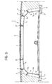
- a respective static hinge 11 providing a hinged bearing is formed between each element 5 and the foundation 3, along the lower edge of the body 5a intended to face the exterior of the structure.
- Each hinge 11 is constituted from a half-portion 11a integrally formed as part of the body 5a of each element 5, in the form of a projection having a cylindrical outer surface, illustrated in detail in Figure 2.
- the other half-portion 11b of the hinge 11 is formed in situ after having positioned the element 5 in a hollow seat on the foundation 3, when the concrete 12 is cast between this seat and the element 5. In this way, once the concrete 12 has solidified, it forms the hollow half-portion 11b which therefore has a shape which corresponds exactly to the half-portion 11a.
- a layer of antifriction material 13 is interposed between them, preferably formed from a sheet of high density polyethylene or other plastics material that is easily deformable and which has a low coefficient of friction in comparison with concrete.
- a pair of bushes 16 in which associated support screws 15 engage is incorporated in each body 5a close to the projection 11a.
- the heads of the screws 15 rest directly on the foundation 3 in such a way that by adjusting their extension the vertical orientation of the associated element 5 can be controlled.
- the dimensions of these screws are such that they can support at least the weight of the element 5 while assembling the structure 1 and before the concrete casting 12 has solidified. After the casting 12 has solidified, the weight of the element 5 and the loads thereon are supported by the hinge 11, so that even if the screws 15 were to collapse, the structure would not be affected.
- Each body 5a is normally intended to be installed vertically. However, where it is desired to space the foundation from a pre-existing site in order to reduce its influence on it during construction, for example, during the construction of flyovers over roads or railways in use, the bodies 5a of the elements 5 may be installed in an inclined position with respect to the vertical, for example, at an angle of 0° to 15°, so that the ground-retaining walls of the structure are inclined. If the inclination of these walls gives rise to a larger span solely at the base of the structure, the span at the intrados of the deck 9 remaining the same, the maximum stresses on the structure 1 are reduced.
- the use of the prefabricated articulated elements makes it very easy to achieve this inclination.
- a prefabricated element 7 in the form of a substantially rectilinear beam which defines a central portion of the deck 9 of the work is interposed centrally between a pair of side elements 5.
- the cross-sectional shape and the disposition of the reinforcement rods of the element 7 are such that it is able to withstand mainly positive bending moments (that is, in the opposite sense from those acting on the elements 5).
- prefabricated articulated elements for the side elements 5 enables the joints between the elements 5 and the central element 7 to be located in the best position, that is, where the bending moments of the deck are at their lowest value. If rigid lateral prefabricated elements of similar shape were used instead, there would be the risk of positioning the joints with the central element 7 in positions that are not optimal, or that transporting by road would not be possible as their dimensions would exceed the shape limit for road transport.
- each central element 7 is provided with opposing nose-like terminal projections 18 which act as reference members and which extend along its central axis.
- the projections 18 are intended to engage seats 19 of a corresponding shape having slightly conical walls, formed centrally at the free ends of the bracket bodies 5c of the side elements 5.
- the structure 1 has the form of a static articulated quadrilateral, which means it is unstable.
- the structure 1 is formed from three substantially rigid elements, in particular, two elements 5 (the articulations of which do not in this state act as hinges since they tend to remain always bent into an L-shape due to the loads applied) and an element 7, joined together by two hinges interposed in the joints between them, and with two further hinges disposed between the elements 5 and the foundation 3.
- the two side elements 5 and the central element 7 must be fixed together. This does not require very strong means as the structure is already balanced with respect to all of the symmetrical loads acting on it. However, unbalancing bending moments caused by possible asymmetric loads may arise in the structure due, for example, to partially completed in situ casting, or accidental movement caused by mobile construction site loads or by the lateral wind pressure, which is generally less than that of the symmetrical loads. In any case, it is desired to achieve the stability of the structure 1 without having to rely on auxiliary temporary shoring installed before the rigidifying castings.
- a pair of threaded bushes 22 is incorporated at the ends of the central element 7, below the projections 18, in which engage respective screws 21 intended to pass through through-holes 23 formed in corresponding positions in the bodies 5c of the side elements 5.
- a further threaded bush 22 is incorporated in each body 5c above the seat 19, engaged by a screw 21 disposed so as to be able to pass through an associated through-hole 23 formed in a corresponding position at an end of the element 7. Pairs of locking nuts 21a enable each screw 21 to be fixed with respect to the ends of the through-holes 23.
- a pair of screws 25 extends from associated threaded bushes 22 embedded in the element 7 at the sides of each projection 18, with heads able to abut against an inclined surface of each free end of the bodies 5c.
- portions of reinforcement rods projecting from the opposite ends of the elements 5 and 7 may be used to join them together, so as to fix these elements in a balanced position.
- the projections 18 are disposed on the bottom of the seats 19.
- the positioning of the central element 7 is completed by adjusting the screws 21 and 23 so as to prevent it from rotating about a horizontal axis perpendicular to the axis of the structure, and stabilise the articulated quadilateral structure.
- the elements 5 and 7 are anchored together and to the adjacent sections of the structure by means of rigidifying castings 27 formed in situ.
- the resistance of the work, at the joints between the elements 5 and 7, against positive bending moments is easily guaranteed by reinforcements inserted in the lower part of the rectilinear joint which extends both between adjacent central elements 7 and between adjacent side elements 5; the resistance against negative bending moments is guaranteed by reinforcements inserted in the casting of the completion slab formed above the deck 9, and resistance against shear forces is guaranteed by reinforcements inserted between each element 7 and the associated pair of side elements 5.
- the structure according to the invention acts in a similar way to the three-hinge arch when faced with this kind of subsidence. Only the displacement of one plinth with respect to the other in the horizontal direction is able to give rise to forces that may damage the structure. But these displacements occur only if significant horizontal forces act on the plinths such as to overcome the frictional resistance of the ground beneath them.
- This structure has many other advantages compared to the three-hinge arch structures.
- the slab or deck may be formed with much thinner walls, as the maximum bending moment caused by the loads which bear on the slab or deck is substantially divided between embedded end moments and middle moments, and is thus approximately one third of that of the simply supported beams usually used for forming the deck (the presence of the inclinations has already reduced it from half to approximately 1/3), and approximately half of the maximum of the prefabricated three-hinge arch structure described in the European Patent mentioned above.
- the reduction in thickness of the walls significantly reduces the cost of the entire structure and increases its torsional deformability thereby making it more able, even more than the three-hinge arch structures, to resist breaking upon twisting, or differential, subsidence of the foundation plinths, that is, subsidence which has the effect that the two base position hinges are no longer coplanar, that is, not on the same horizontal plane.
- a particularly interesting advantage of the structure according to the invention is due to the fact that the dimensions of its elements are within the shape limits for road transport even for structures having spans much greater than that which are possible with road-transportable three-hinge arch structures.
- the entire length of the central element 7 is caught within the maximum span so that from a maximum span of approximately 14-15 m, typical of the three-hinge arch structures, a maximum span of up to approximately 25 m may be achieved.
Landscapes
- Engineering & Computer Science (AREA)
- Architecture (AREA)
- Civil Engineering (AREA)
- Structural Engineering (AREA)
- Electromagnetism (AREA)
- Physics & Mathematics (AREA)
- Paleontology (AREA)
- General Engineering & Computer Science (AREA)
- Mining & Mineral Resources (AREA)
- General Life Sciences & Earth Sciences (AREA)
- Life Sciences & Earth Sciences (AREA)
- Environmental & Geological Engineering (AREA)
- Lining And Supports For Tunnels (AREA)
- Load-Engaging Elements For Cranes (AREA)
- Bridges Or Land Bridges (AREA)
- Underground Structures, Protecting, Testing And Restoring Foundations (AREA)
- Foundations (AREA)
- Artificial Fish Reefs (AREA)
- Rod-Shaped Construction Members (AREA)
- Buildings Adapted To Withstand Abnormal External Influences (AREA)
- Piles And Underground Anchors (AREA)
Claims (11)
- Vorgefertige Struktur zum Bauen von Freiluftkonstruktionen, insbesondere von Autobahn-Hochstraßen, Unterführungen, Brücken, Tunnels, Tiefgaragen und dergleichen, umfassend eine Mehrzahl an vorgefertigten, aus Stahlbeton gebildeten Elementen (5, 7), die die Seitenwände und das Dach (9) der Konstruktion definieren können, und zwar mit benachbarten Längsabschnitten der Struktur (1), die dazu bestimmt ist, auf einem an der Basis der Konstruktion gebildeten Fundament (3) zu ruhen, wobei jeder Abschnitt der Struktur (1) ein Paar vorgefertigte Seitenelemente (5) umfasst, die durch ein damit in Verbindung stehendes, ein Drehlager bereitstellendes statisches Drehgelenk (11) auf dem Fundament (3) ruhen und dazu bestimmt sind, symmetrisch zur Achse der Konstruktion angeordnet zu werden, um im aufgestellten Zustand eine im Wesentlichen L-förmige Konfiguration anzunehmen, sowie ein im Wesentlichen geradliniges vorgefertigtes Element (7), das zentral zwischen zwei Seitenelementen (5) angeordnet ist und damit verankert ist, um einen zentralen Teil des Daches (9) der Konstruktion zu definieren.
- Struktur nach Anspruch 1, dadurch gekennzeichnet, dass jedes Seitenelement (5) drei geradlinige Körper (5a, 5b, 5c) umfasst, von denen ein erster Endkörper (5a) einen Ständer der Struktur (1) definiert, ein Zwischenkörper (5b) einen schrägen Teil definiert, und ein weiterer Endkörper (5c) einen Träger definiert, wobei diese Körper (5a, 5b, 5c) dazu adaptiert sind, zwischen dem Stadium der Vorfertigung und dem Stadium der endgültigen Positionierung durch ein Biegen der sich zwischen benachbarten Körpern erstreckenden Verstärkungsstangen des Elements (5) zusammen gelenkig angebracht zu werden.
- Struktur nach Anspruch 2, dadurch gekennzeichnet, dass jeder erste Endkörper (5a) jedes Seitenelements (5) dazu bestimmt ist, in einer zur Senkrechten geneigten Position aufgestellt zu werden, und zwar in einem Winkel von weniger als ca. 15°.
- Struktur nach Anspruch 2 oder 3, dadurch gekennzeichnet, dass jeder der ersten Körper (5a) einen Vorsprung (11a) umfasst, der durch eine zylindrische Oberfläche definiert und dazu bestimmt ist, einen Halbteil des statischen Drehgelenks (11) zu bilden.
- Struktur nach Anspruch 4, dadurch gekennzeichnet, dass jedes statische Drehgelenk (11) einen hohlen Halbteil (11b) umfasst, der durch eine zylindrische Oberfläche begrenzt ist, die mit der des Vorsprungs (11a) korrespondiert, welcher Halbteil vor Ort zwischen dem ersten Körper (5a) des damit in Verbindung stehenden Seitenelements (5) und dem Fundament (3) durch ein Betongussstück (12) gebildet wird.
- Struktur nach Anspruch 5, dadurch gekennzeichnet, dass eine Schicht aus Antifriktionskunststoff (13) zwischen den Halbteilen (11a, 11b) jedes statischen Drehgelenks (11) angeordnet ist.
- Struktur nach irgendeinem der Ansprüche 4 bis 6, dadurch gekennzeichnet, dass sich in der Nähe des jeweiligen Vorsprungs (11a) der ersten Körper (5a) einstellbare Tragvorrichtungen (15, 16) befinden, die zumindest das Gewicht des damit in Verbindung stehenden Seitenelements (5) während der Montage der Struktur (1) und vor der Einsatzbereitschaft des zweiten Halbteils (11b) des damit in Verbindung stehenden statischen Drehgelenks (11) tragen können.
- Struktur nach irgendeinem der Ansprüche 1 bis 7, dadurch gekennzeichnet, dass die Seitenelemente (5) und/oder die zentralen Elemente (7) mit Bezugsvorrichtungen und Vorrichtungen zur gegenseitigen Sicherung (18, 19, 21, 21a, 22, 23, 25) versehen sind, um sie aneinander zu befestigen, bevor sie durch ein starr machendes Gussstück (27) verankert werden.
- Struktur nach Anspruch 8, dadurch gekennzeichnet, dass jedes zentrale Element (7) mit gegenüberliegenden nasenähnlichen Endvorsprüngen (18) versehen ist, die sich entlang seiner Mittelachse erstrecken und dazu bestimmt sind, damit in Verbindung stehende, an den freien Enden der Trägerkörper (5c) der Seitenelemente (5) gebildete Sitze (19) in Eingriff zu bringen.
- Struktur nach Anspruch 9, dadurch gekennzeichnet, dass das zentrale Element (7) und/oder die Seitenelemente (5) mit einstellbaren Schraubenelementen (21, 25) zum gegenseitigen Verbinden versehen sind, wobei diese mit einem dieser Elemente verbunden sind und mit dem anderen dieser Elemente zusammenwirken, um es zu erlauben, dass das zentrale Element (7) während der Montage der Struktur (1) an den Seitenelementen (5) befestigt wird.
- Struktur nach irgendeinem der Ansprüche 1 bis 10, dadurch gekennzeichnet, dass vor Ort in die Fugen zwischen mehreren Seitenelementen und zentralen Elementen benachbarter Abschnitte (1) der Struktur positionierte Verstärkungsstangen in die starr machenden Gussstücke (27) einbezogen werden, die ein zentrales Element (7) und ein Paar Seitenelemente (5) miteinander verankern.
Applications Claiming Priority (3)
| Application Number | Priority Date | Filing Date | Title |
|---|---|---|---|
| ITTO950922 | 1995-11-17 | ||
| IT95TO000922A IT1281031B1 (it) | 1995-11-17 | 1995-11-17 | Struttura prefabbricata per la realizzazione di opere costruite a cielo aperto, particolarmente per cavalcavia autostradali, |
| PCT/EP1996/004989 WO1997019231A1 (en) | 1995-11-17 | 1996-11-14 | A prefabricated structure for the construction of overhead or underground works |
Publications (2)
| Publication Number | Publication Date |
|---|---|
| EP0861358A1 EP0861358A1 (de) | 1998-09-02 |
| EP0861358B1 true EP0861358B1 (de) | 2001-07-25 |
Family
ID=11413966
Family Applications (1)
| Application Number | Title | Priority Date | Filing Date |
|---|---|---|---|
| EP96938201A Expired - Lifetime EP0861358B1 (de) | 1995-11-17 | 1996-11-14 | Vorgefertigte struktur zum bauen von oberirdischen oder unterirdischen konstruktionen |
Country Status (10)
| Country | Link |
|---|---|
| US (1) | US6129484A (de) |
| EP (1) | EP0861358B1 (de) |
| AT (1) | ATE203579T1 (de) |
| AU (1) | AU7571396A (de) |
| DE (1) | DE69614134T2 (de) |
| ES (1) | ES2162112T3 (de) |
| IL (1) | IL124416A (de) |
| IT (1) | IT1281031B1 (de) |
| PT (1) | PT861358E (de) |
| WO (1) | WO1997019231A1 (de) |
Families Citing this family (20)
| Publication number | Priority date | Publication date | Assignee | Title |
|---|---|---|---|---|
| IT1297270B1 (it) * | 1997-06-25 | 1999-08-09 | Rocksoil S P A | Procedimento costruttivo per l'allargamento di gallerie stradali, autostradali o ferroviarie,senza interrompere il traffico |
| IL138609A0 (en) | 1998-04-30 | 2001-10-31 | Agouron Pharma | Antipicornaviral compounds, their preparation and use |
| AU779321B2 (en) | 1999-08-04 | 2005-01-20 | Agouron Pharmaceuticals, Inc. | Antipicornaviral compounds and compositions, their pharmaceutical uses, and materials for their synthesis |
| PA8507801A1 (es) | 1999-12-03 | 2002-08-26 | Agouron Pharma | Compuestos y composiciones antipicornavirales, sus usos farmaceuticos y los materiales para su sintesis |
| US6854928B2 (en) * | 2002-01-30 | 2005-02-15 | Con/Span Bridge Systems Ltd. | Precast concrete culvert system |
| ITTO20030243A1 (it) * | 2003-03-28 | 2004-09-29 | Carlo Chiaves | Procedimento per realizzare un segmento di un'opera |
| ITTO20030519A1 (it) * | 2003-07-08 | 2005-01-09 | Carlo Chiaves | Sistema d'appoggio articolabile di un elemento |
| AU2011216967B2 (en) * | 2010-02-19 | 2016-10-20 | Council Of Scientific & Industrial Research | A device for roof support of underground mine/tunnel |
| AU2013217639B2 (en) | 2012-02-06 | 2016-11-03 | Contech Engineered Solutions LLC | Concrete bridge system and related methods |
| US9970166B2 (en) | 2012-02-06 | 2018-05-15 | Contech Engineered Solutions LLC | Concrete bridge system and related methods |
| USD697634S1 (en) | 2012-02-20 | 2014-01-14 | Contech Engineered Solutions LLC | Upper portion of a concrete bridge unit |
| USD694910S1 (en) | 2012-04-03 | 2013-12-03 | Contech Engineered Solutions LLC | Upper portion of a concrete bridge unit |
| US9243380B2 (en) * | 2013-06-10 | 2016-01-26 | Terratech Consulting Ltd. | Reinforced arch with floating footer and method of constructing same |
| US11536017B2 (en) | 2016-10-26 | 2022-12-27 | Envirokeeper, LLC | Modular precast concrete water storage device and system |
| CL2019000711A1 (es) | 2019-02-20 | 2019-08-16 | Dsi Tunneling Llc | Sistema y procedimiento para soporte de tunel. |
| CN111926710A (zh) * | 2020-07-29 | 2020-11-13 | 中铁二十局集团第六工程有限公司 | 多股道铁路架空固定装置 |
| CN112376611B (zh) * | 2020-11-10 | 2022-10-21 | 北京城建道桥建设集团有限公司 | 一种分离式立交系统施工方法 |
| CN112482188B (zh) * | 2020-11-26 | 2022-06-24 | 温州市市政管理中心 | 一种拱桥加固结构及其施工方法 |
| CN112900489A (zh) * | 2021-01-22 | 2021-06-04 | 中建八局轨道交通建设有限公司 | 高低跨处的管廊施工方法及其施工装置 |
| CN118441608B (zh) * | 2024-04-19 | 2024-12-10 | 湖北工业大学 | 可主动减载式高填方涵洞及施工方法 |
Family Cites Families (9)
| Publication number | Priority date | Publication date | Assignee | Title |
|---|---|---|---|---|
| CH565304A5 (de) * | 1973-05-25 | 1975-08-15 | Stuessi Rudolf | |
| US4290246A (en) * | 1978-11-22 | 1981-09-22 | Hilsey Arthur F | Multi-purpose precast concrete panels, and methods of constructing concrete structures employing the same |
| US4836714A (en) * | 1981-11-17 | 1989-06-06 | Marcel Matiere | Enclosed structures of very large cross-section, such as conduits, silos or shelters |
| JPS58501957A (ja) * | 1981-11-17 | 1983-11-17 | マテイエル マルセル | 導管、サイロ又はシェルタのような中空構造物の製造方法 |
| FR2547607B1 (fr) * | 1983-06-20 | 1986-03-21 | Matiere Marcel | Procede d'obtention de conduits souterrains de grande section, se trouvant sous forte couverture, et conduits obtenus par ce procede |
| IT1180072B (it) * | 1984-06-05 | 1987-09-23 | Carlo Chiaves | Struttura prefabbricata di sostegno e copertura particolarmente per la realizzazione di gallerie ponti e simili |
| CA1313956C (en) * | 1988-11-21 | 1993-03-02 | Hyun-Ho Hwang | Prefabricated culvert system |
| US5180254A (en) * | 1989-04-10 | 1993-01-19 | Marcel Matiere | Fluid-conveying conduit |
| US5118218A (en) * | 1991-06-24 | 1992-06-02 | Syro Steel Company | Box culvert without rib stiffeners |
-
1995
- 1995-11-17 IT IT95TO000922A patent/IT1281031B1/it active IP Right Grant
-
1996
- 1996-11-14 PT PT96938201T patent/PT861358E/pt unknown
- 1996-11-14 DE DE69614134T patent/DE69614134T2/de not_active Expired - Lifetime
- 1996-11-14 AT AT96938201T patent/ATE203579T1/de active
- 1996-11-14 IL IL12441696A patent/IL124416A/xx not_active IP Right Cessation
- 1996-11-14 AU AU75713/96A patent/AU7571396A/en not_active Abandoned
- 1996-11-14 EP EP96938201A patent/EP0861358B1/de not_active Expired - Lifetime
- 1996-11-14 ES ES96938201T patent/ES2162112T3/es not_active Expired - Lifetime
- 1996-11-14 WO PCT/EP1996/004989 patent/WO1997019231A1/en not_active Ceased
- 1996-11-17 US US09/068,647 patent/US6129484A/en not_active Expired - Lifetime
Also Published As
| Publication number | Publication date |
|---|---|
| US6129484A (en) | 2000-10-10 |
| EP0861358A1 (de) | 1998-09-02 |
| IL124416A (en) | 2000-12-06 |
| PT861358E (pt) | 2002-01-30 |
| WO1997019231A1 (en) | 1997-05-29 |
| ITTO950922A0 (de) | 1995-11-17 |
| DE69614134T2 (de) | 2002-03-14 |
| ATE203579T1 (de) | 2001-08-15 |
| IL124416A0 (en) | 1998-12-06 |
| ES2162112T3 (es) | 2001-12-16 |
| ITTO950922A1 (it) | 1997-05-17 |
| DE69614134D1 (de) | 2001-08-30 |
| IT1281031B1 (it) | 1998-02-11 |
| AU7571396A (en) | 1997-06-11 |
Similar Documents
| Publication | Publication Date | Title |
|---|---|---|
| EP0861358B1 (de) | Vorgefertigte struktur zum bauen von oberirdischen oder unterirdischen konstruktionen | |
| US6234716B1 (en) | Underground structural work including prefabricated elements associated with piles and a process for its production | |
| US7461427B2 (en) | Bridge construction system and method | |
| US6988337B1 (en) | Means and method for constructing a fully precast top arch overfilled system | |
| US20070094960A1 (en) | Composite structural member with longitudinal structural haunch | |
| WO2001096665A1 (en) | Method of constructing simple and continuous composite bridges | |
| US5121518A (en) | Cable-stayed bridge and construction process | |
| CN111424521A (zh) | 一种钢混梁v形支承连续刚构桥 | |
| KR102274358B1 (ko) | 교량 구조물의 캔틸레버용 프리캐스트 바닥판 | |
| Ingebrigtsen | Stolma bridge, norway | |
| US6018834A (en) | Method for building a bridge and bridge built according to said method | |
| CN113789711B (zh) | 一种nc-uhpc组合装配式预应力混凝土箱梁、施工方法及其桥梁 | |
| EP1061177B1 (de) | Freiträgerstruktur für Strassenschutz | |
| KR102199927B1 (ko) | 부반력 제어 및 낙교 방지 강재박스 거더교 | |
| JP2963879B2 (ja) | 橋 桁 | |
| CN215367299U (zh) | 一种基坑支护系统 | |
| Čandrlić et al. | Design and construction of the Maslenica Highway Bridge | |
| CN114875767A (zh) | 一种撑杆式推力拱桥及其施工方法 | |
| KR102895966B1 (ko) | 복합판형 강합성 거더를 이용한 라멘교 시공방법 및 그에 따라 시공된 라멘교 | |
| Weizenegger | Hybrid frame bridge, river saale, Merseburg, Germany | |
| PL197925B1 (pl) | Dźwigar prefabrykowany do budowy mostów i sposób jego wytwarzania | |
| CN114703735B (zh) | 一种多跨上承式连续拱桥拱顶构造 | |
| CN112538862A (zh) | 一种施工升降机基础及其施工方法 | |
| KR102521965B1 (ko) | 횡방향 및 지점부 보강 구조가 구비된 교량 | |
| CN120250497A (zh) | 一种轻型撑拉式桥台结构及施工方法 |
Legal Events
| Date | Code | Title | Description |
|---|---|---|---|
| PUAI | Public reference made under article 153(3) epc to a published international application that has entered the european phase |
Free format text: ORIGINAL CODE: 0009012 |
|
| 17P | Request for examination filed |
Effective date: 19980617 |
|
| AK | Designated contracting states |
Kind code of ref document: A1 Designated state(s): AT BE CH DE DK ES FR GB GR IE IT LI LU NL PT SE |
|
| 17Q | First examination report despatched |
Effective date: 19980814 |
|
| GRAG | Despatch of communication of intention to grant |
Free format text: ORIGINAL CODE: EPIDOS AGRA |
|
| GRAG | Despatch of communication of intention to grant |
Free format text: ORIGINAL CODE: EPIDOS AGRA |
|
| GRAH | Despatch of communication of intention to grant a patent |
Free format text: ORIGINAL CODE: EPIDOS IGRA |
|
| GRAH | Despatch of communication of intention to grant a patent |
Free format text: ORIGINAL CODE: EPIDOS IGRA |
|
| GRAA | (expected) grant |
Free format text: ORIGINAL CODE: 0009210 |
|
| AK | Designated contracting states |
Kind code of ref document: B1 Designated state(s): AT BE CH DE DK ES FR GB GR IE IT LI LU NL PT SE |
|
| PG25 | Lapsed in a contracting state [announced via postgrant information from national office to epo] |
Ref country code: LI Free format text: LAPSE BECAUSE OF FAILURE TO SUBMIT A TRANSLATION OF THE DESCRIPTION OR TO PAY THE FEE WITHIN THE PRESCRIBED TIME-LIMIT Effective date: 20010725 Ref country code: CH Free format text: LAPSE BECAUSE OF FAILURE TO SUBMIT A TRANSLATION OF THE DESCRIPTION OR TO PAY THE FEE WITHIN THE PRESCRIBED TIME-LIMIT Effective date: 20010725 |
|
| REF | Corresponds to: |
Ref document number: 203579 Country of ref document: AT Date of ref document: 20010815 Kind code of ref document: T |
|
| REG | Reference to a national code |
Ref country code: CH Ref legal event code: EP |
|
| REG | Reference to a national code |
Ref country code: IE Ref legal event code: FG4D |
|
| REF | Corresponds to: |
Ref document number: 69614134 Country of ref document: DE Date of ref document: 20010830 |
|
| PG25 | Lapsed in a contracting state [announced via postgrant information from national office to epo] |
Ref country code: SE Free format text: LAPSE BECAUSE OF FAILURE TO SUBMIT A TRANSLATION OF THE DESCRIPTION OR TO PAY THE FEE WITHIN THE PRESCRIBED TIME-LIMIT Effective date: 20011025 Ref country code: DK Free format text: LAPSE BECAUSE OF FAILURE TO SUBMIT A TRANSLATION OF THE DESCRIPTION OR TO PAY THE FEE WITHIN THE PRESCRIBED TIME-LIMIT Effective date: 20011025 |
|
| PG25 | Lapsed in a contracting state [announced via postgrant information from national office to epo] |
Ref country code: GR Free format text: LAPSE BECAUSE OF FAILURE TO SUBMIT A TRANSLATION OF THE DESCRIPTION OR TO PAY THE FEE WITHIN THE PRESCRIBED TIME-LIMIT Effective date: 20011026 |
|
| PG25 | Lapsed in a contracting state [announced via postgrant information from national office to epo] |
Ref country code: LU Free format text: LAPSE BECAUSE OF NON-PAYMENT OF DUE FEES Effective date: 20011114 Ref country code: IE Free format text: LAPSE BECAUSE OF FAILURE TO SUBMIT A TRANSLATION OF THE DESCRIPTION OR TO PAY THE FEE WITHIN THE PRESCRIBED TIME-LIMIT Effective date: 20011114 |
|
| REG | Reference to a national code |
Ref country code: ES Ref legal event code: FG2A Ref document number: 2162112 Country of ref document: ES Kind code of ref document: T3 |
|
| EN | Fr: translation not filed | ||
| REG | Reference to a national code |
Ref country code: GB Ref legal event code: IF02 |
|
| REG | Reference to a national code |
Ref country code: PT Ref legal event code: SC4A Free format text: AVAILABILITY OF NATIONAL TRANSLATION Effective date: 20011025 |
|
| REG | Reference to a national code |
Ref country code: CH Ref legal event code: PL |
|
| EN | Fr: translation not filed |
Free format text: BO 01/51 PAGES: 265, IL Y A LIEU DE SUPPRIMER: LA MENTION DE LA NON REMISE. LA REMISE EST PUBLIEE DANS LE PRESENT BOPI. |
|
| ET | Fr: translation filed | ||
| PLBE | No opposition filed within time limit |
Free format text: ORIGINAL CODE: 0009261 |
|
| STAA | Information on the status of an ep patent application or granted ep patent |
Free format text: STATUS: NO OPPOSITION FILED WITHIN TIME LIMIT |
|
| 26N | No opposition filed | ||
| REG | Reference to a national code |
Ref country code: IE Ref legal event code: MM4A |
|
| PGFP | Annual fee paid to national office [announced via postgrant information from national office to epo] |
Ref country code: AT Payment date: 20101112 Year of fee payment: 15 |
|
| PGFP | Annual fee paid to national office [announced via postgrant information from national office to epo] |
Ref country code: GB Payment date: 20101118 Year of fee payment: 15 |
|
| PGFP | Annual fee paid to national office [announced via postgrant information from national office to epo] |
Ref country code: PT Payment date: 20111114 Year of fee payment: 16 Ref country code: NL Payment date: 20111128 Year of fee payment: 16 |
|
| PGFP | Annual fee paid to national office [announced via postgrant information from national office to epo] |
Ref country code: BE Payment date: 20111110 Year of fee payment: 16 |
|
| PGFP | Annual fee paid to national office [announced via postgrant information from national office to epo] |
Ref country code: DE Payment date: 20120131 Year of fee payment: 16 |
|
| PGFP | Annual fee paid to national office [announced via postgrant information from national office to epo] |
Ref country code: ES Payment date: 20121120 Year of fee payment: 17 |
|
| PGFP | Annual fee paid to national office [announced via postgrant information from national office to epo] |
Ref country code: FR Payment date: 20121220 Year of fee payment: 17 |
|
| REG | Reference to a national code |
Ref country code: PT Ref legal event code: MM4A Free format text: LAPSE DUE TO NON-PAYMENT OF FEES Effective date: 20130514 |
|
| BERE | Be: lapsed |
Owner name: *CHIAVES CARLO Effective date: 20121130 |
|
| REG | Reference to a national code |
Ref country code: NL Ref legal event code: V1 Effective date: 20130601 |
|
| REG | Reference to a national code |
Ref country code: AT Ref legal event code: MM01 Ref document number: 203579 Country of ref document: AT Kind code of ref document: T Effective date: 20121114 |
|
| GBPC | Gb: european patent ceased through non-payment of renewal fee |
Effective date: 20121114 |
|
| PG25 | Lapsed in a contracting state [announced via postgrant information from national office to epo] |
Ref country code: AT Free format text: LAPSE BECAUSE OF NON-PAYMENT OF DUE FEES Effective date: 20121114 |
|
| PG25 | Lapsed in a contracting state [announced via postgrant information from national office to epo] |
Ref country code: PT Free format text: LAPSE BECAUSE OF NON-PAYMENT OF DUE FEES Effective date: 20130514 Ref country code: NL Free format text: LAPSE BECAUSE OF NON-PAYMENT OF DUE FEES Effective date: 20130601 Ref country code: BE Free format text: LAPSE BECAUSE OF NON-PAYMENT OF DUE FEES Effective date: 20121130 |
|
| REG | Reference to a national code |
Ref country code: DE Ref legal event code: R119 Ref document number: 69614134 Country of ref document: DE Effective date: 20130601 |
|
| PG25 | Lapsed in a contracting state [announced via postgrant information from national office to epo] |
Ref country code: DE Free format text: LAPSE BECAUSE OF NON-PAYMENT OF DUE FEES Effective date: 20130601 |
|
| PG25 | Lapsed in a contracting state [announced via postgrant information from national office to epo] |
Ref country code: GB Free format text: LAPSE BECAUSE OF NON-PAYMENT OF DUE FEES Effective date: 20121114 |
|
| REG | Reference to a national code |
Ref country code: FR Ref legal event code: ST Effective date: 20140731 |
|
| PG25 | Lapsed in a contracting state [announced via postgrant information from national office to epo] |
Ref country code: FR Free format text: LAPSE BECAUSE OF NON-PAYMENT OF DUE FEES Effective date: 20131202 |
|
| REG | Reference to a national code |
Ref country code: ES Ref legal event code: FD2A Effective date: 20150327 |
|
| PGFP | Annual fee paid to national office [announced via postgrant information from national office to epo] |
Ref country code: IT Payment date: 20141114 Year of fee payment: 19 |
|
| PG25 | Lapsed in a contracting state [announced via postgrant information from national office to epo] |
Ref country code: ES Free format text: LAPSE BECAUSE OF NON-PAYMENT OF DUE FEES Effective date: 20131115 |
|
| PG25 | Lapsed in a contracting state [announced via postgrant information from national office to epo] |
Ref country code: IT Free format text: LAPSE BECAUSE OF NON-PAYMENT OF DUE FEES Effective date: 20151114 |