EP0860140A2 - Wasserenthärtungsvorrichtung in einer Geschirrspülmaschine - Google Patents
Wasserenthärtungsvorrichtung in einer Geschirrspülmaschine Download PDFInfo
- Publication number
- EP0860140A2 EP0860140A2 EP98830071A EP98830071A EP0860140A2 EP 0860140 A2 EP0860140 A2 EP 0860140A2 EP 98830071 A EP98830071 A EP 98830071A EP 98830071 A EP98830071 A EP 98830071A EP 0860140 A2 EP0860140 A2 EP 0860140A2
- Authority
- EP
- European Patent Office
- Prior art keywords
- water
- dishwashing machine
- softening system
- water softening
- machine according
- Prior art date
- Legal status (The legal status is an assumption and is not a legal conclusion. Google has not performed a legal analysis and makes no representation as to the accuracy of the status listed.)
- Withdrawn
Links
Images

Classifications
-
- A—HUMAN NECESSITIES
- A47—FURNITURE; DOMESTIC ARTICLES OR APPLIANCES; COFFEE MILLS; SPICE MILLS; SUCTION CLEANERS IN GENERAL
- A47L—DOMESTIC WASHING OR CLEANING; SUCTION CLEANERS IN GENERAL
- A47L15/00—Washing or rinsing machines for crockery or tableware
- A47L15/42—Details
- A47L15/4229—Water softening arrangements
Definitions
- the present invention refers to a water softening system in a dishwashing machine of the type comprising a decalcifier device of mains water containing decalcifying resins, a salt container for producing a brine solution to regenerate the resins contained in the decalcifier device, a container for the metering of regeneration water having a plurality of tanks to for supplying volumetrically defined amounts of water to the salt container to produce the regenerating brine solution, said tanks, which are so arranged to be filled up in parallel, being of the air-trap kind and fitted with upper vents, whose opening determines the filling of said tanks.
- washing machines are equipped with systems for softening the water from the mains, which often contains a big quantity of limestone notoriously harmful for a good operation of the washing machine. Therefore, water from the mains is conveniently decalcified letting it flow first through a decalcifier device containing resins, which through a ionic exchange fix the calcium salts contained in the water and produce a low hardness water to be used without any difficulties by the washing machine.
- Resins contained in the decalcifier device need to be reactivated, at given intervals, to remove calcium and magnesium that have accumulated.
- a tank is provided to be filled by the user with a proper salt, wherein with the addition of a proper water volume a saline solution, also called brine, is produced. Said brine flows over the resins and removes the accumulated calcium through a chemical reaction.
- water hardness may change significantly according to the place where the washing machine is installed and also with time.
- the water volume to be used for resin regeneration may then be higher or lower, according to a higher or lower hardness degree of the water from the mains.
- the water volume to be stored and then be used for resin regeneration can be established through the opening and closing of said vents.
- Said vents are opened and closed by acting on a plurality of small pipes coming out of said vents.
- Said pipes are usually connected with a rotary selector located outside the container, normally at a considerable distance from it (i.e. pipes must be adequately long) and can be progressively opened to connect the various chambers with the environment outside.
- This adjustment is usually performed by the installer of the washing machine, after evaluating the hardness of the mains water, and will be eventually repeated if any changes occur to the hardness of the water from the mains.
- This control procedure has some drawbacks for its manufacturing complexity, due to the presence of small pipes and a separate selector. Moreover, said pipes may come off and cause a difficult in assembly, specifically if they are more than one or two.
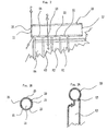
- a tank 1 is represented, of the type used for metering the water to be delivered to a washing tub, not represented here.
- Said tank 1 is manufactured by moulding a plastic material.
- Water is supplied from the mains through an inlet pipe 2, flows through an air breaker 3 and reaches a decalcifier device DD through a pipe 4.
- Water from the decalcifier device DD is returned to the tank 1 through a pipe 5.
- the water contained in the tank 1 can then be discharged into the tub through a pipe 6, by actuation of a proper solenoid valve EVI.
- a compartment V contains the water to be introduced into the tub and a compartment R, which is apt to contain the water for regenerating the resins of the decalcifier device DD.
- the compartment R has an outlet 7 connecting it with a salt container SS once the actuation of a solenoid valve EV2 has occurred.
- the compartment R is divided in a section RN, wherein the water overflowing the compartment V is collected, and other four columns R1, R2, R3, R4. Said columns R1, R2, R3, R4 are each provided with a vent, S1, S2, S3, S4 respectively.
- a selector 8 operates on said vents S1, S2, S3, S4, which is integral with them.
- the selector 8 consists of a selection rod 9 and a seal cylinder 10.
- compartment R can be filled with the water overflowing the compartment V after its filling.
- section RN of compartment R will always be filled, whereas columns R1, R2, R3, R4 are only filled if their relevant vents S1, S2, S3 or S4 are opened by the selector 8.
- the outlet 7 allows discharge of both the section R and columns R1, R2, R3 and R4, should they be full of water.
- Fig. 2 the seal cylinder 10 is represented.
- Said seal cylinder 10 is made of plastic material during the moulding process of the tank 1 and communicates with columns R1, R2, R3, R4 through vents S1, S2, S3, S4.
- the seal cylinder 10 has an inlet opening 11 and an outlet opening 12. Near the inlet opening 11 some grooves 15 are provided, of which only the upper one can be seen in Fig. 2. The function of grooves 15 will be described in the following.
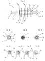
- Fig. 2a a section according to the axis Q is represented, where the column R3 is shown with its relevant vent S3, that puts column R3 in communication with the inside of the seal cylinder 10.
- a section according to the axis P is represents, showing the inlet opening 11 wherein the grooves 15 are obtained, which are spaced at substantially regular distances.
- Fig. 3 the selection rod 9 is represented, being inserted in the seal cylinder 10.
- Said selection rod 9 consists of a shaft 16, having a head 17, which ends on the opposite side with two engaging teeth 18.
- the shaft 16 is hollow and has an internal conduit 23, that ends between the engaging teeth 18; moreover, its central portion is contained inside a resilient cylinder 19.
- Four passages P1, P2, P3, P4, leading to the conduit 23, are defined both through the shaft 16 and the surrounding resilient cylinder 19.
- the shaft 16 is made of hard plastic material, whereas the resilient cylinder 19 is obtained by a co-moulding process of an elastomeric material.
- Fig. 3a the head 17 ofthe shaft 16 is shown, which has a seat 20 for allowing the shaft 16 to be rotated, for example through a screwdriver.
- References V1, V2, V3, V4 e V5 for the position of selector 8 are also indicated, corresponding substantially to the positions of the grooves 15 on the inlet opening 11.
- Fig. 3b represents a section according to the axis G of the shaft 16, showing an indentation 22, which is jointly used with grooves 15 to obtain reference trips corresponding to the references.
- indentation 22 surely selecting one of the possible positions defined by grooves 15 and references V1, V2, V3, V4, V5, will let the user to safely select the resins regeneration degree he wants to set.
- Fig. 3c a section is represented according to the axis H, showing how the resilient cylinder 19 is assembled around the shaft 16.
- the selection rod 9 is inserted in the seal cylinder through the inlet opening 22, comes out of the outlet 12 and is engaged with the outlet opening 12, by means of the engaging teeth 18 themselves, so hindering a removal of the selection rod 10 and permitting a complete shaft rotation 16.
- Figs. 3d, 3e, 3f and 3g illustrate four sections according to axis K, L, M, N, respectively, which show the form of the four passages P1, P2, P3, P4.
- Said passages P1, P2, P3, P4 have an increasing width and are so positioned for allowing the conduit 23 to communicate with one or more vents S1, S2, S3, S4 of columns R1, R2, R3, R4 by means of subsequent rotations of the selection rod 9. Therefore, configurations of passages P1, P2, P3, P4 allows an initial position V1, where all vents S1, S2, S3, S4 are plugged by the selection rod 9 and specifically by the resilient cylinder 19, which is made of a material to favour air seal. Under this usage condition, only the section RN can be filled with water.
- the passage P1 will be in line with the vent S1 and let the column R1 to be filled, thus increasing the water volume available for the resins regeneration. In this position, all other vents S2, S3, S4 will be plugged by the selection rod 10. If the selection rod 9 of selector 8 is brought to position V3, the passage P1, having a large angular opening, will always have a portion in line with the vent S1, whereas the passage P2 comes in line with the vent S2, leaving the column R2 available for water filling. It is then possible to go through positions V4 and V5, putting the other passages P3 and P4 in line with vents S3 and S4, respectively.
- the softening system described above allows the selection of the water volume for regeneration purposes, which is simple, clear and above all easily accessible, although the selector is directly in contact with the water metering tank, or manufactured integrally with said tank.
- the selection rod can easily reach the front of the washing machine, making its access extremely easy with the aid of a screwdriver.
- This means a great advantage since with the selector described above it is possible to select the water volume for resin regeneration actuating a compact and sturdy control element, being available on the control panel of the washing machine. This is also beneficial for the installer of the machine or for service and maintenance operators or for users themselves, who can eventually operate with the aid of a simple and clear control element, in case of a malfunction of the washing machine.
- the water softening system described above by way of example allows a most flexible selection of the water volumes to be used for resin regeneration, which may be changed according to requirements, without any restrictions due to manufacturing problems, such as in the instance where small tubes are required. Also, adjustments are fully reversible and can be made any time.
- the selector is of a very simple manufacturing, being mainly obtained during the tank moulding process, except for the selection rod.
- Another advantage is that no components may come off (such as small pipes), be lost or get broken, jeopardizing the operation of the softening system.
- the number of columns can be larger or smaller, according to the requirements and control degree to be achieved.
- the form and arrangement of the passages on the selection rod may differ, as it is also for the opening and closing sequence of the column vents.
- the selection rod may be rotated by a proper knob instead of using a screwdriver.
Applications Claiming Priority (2)
| Application Number | Priority Date | Filing Date | Title |
|---|---|---|---|
| ITTO970135 | 1997-02-18 | ||
| IT97TO000135A IT1291036B1 (it) | 1997-02-18 | 1997-02-18 | Sistema di dolcificazione dell'acqua in una macchina lavastoviglie. |
Publications (2)
| Publication Number | Publication Date |
|---|---|
| EP0860140A2 true EP0860140A2 (de) | 1998-08-26 |
| EP0860140A3 EP0860140A3 (de) | 1998-12-02 |
Family
ID=11415392
Family Applications (1)
| Application Number | Title | Priority Date | Filing Date |
|---|---|---|---|
| EP98830071A Withdrawn EP0860140A3 (de) | 1997-02-18 | 1998-02-16 | Wasserenthärtungsvorrichtung in einer Geschirrspülmaschine |
Country Status (2)
| Country | Link |
|---|---|
| EP (1) | EP0860140A3 (de) |
| IT (1) | IT1291036B1 (de) |
Cited By (5)
| Publication number | Priority date | Publication date | Assignee | Title |
|---|---|---|---|---|
| US7988790B2 (en) | 2002-04-10 | 2011-08-02 | Fisher & Paykel Appliances Limited | Washing appliance water softener |
| KR101054130B1 (ko) | 2004-05-20 | 2011-08-03 | 엘지전자 주식회사 | 식기 세척기의 에어 브레이크 구조 |
| EP2976979A1 (de) * | 2014-07-21 | 2016-01-27 | LG Electronics Inc. | Waschvorrichtung |
| WO2022019492A1 (ko) * | 2020-07-22 | 2022-01-27 | 삼성전자주식회사 | 식기 세척기 |
| WO2022131681A1 (ko) * | 2020-12-15 | 2022-06-23 | 엘지전자 주식회사 | 식기세척기 |
Citations (3)
| Publication number | Priority date | Publication date | Assignee | Title |
|---|---|---|---|---|
| DE3631687A1 (de) * | 1986-09-18 | 1988-03-24 | Licentia Gmbh | Dosiergeraet fuer fluessigkeiten |
| EP0570872A1 (de) * | 1992-05-16 | 1993-11-24 | AWECO Kunststofftechnik Gerätebau GmbH & Co. KG | Wasserenthärter für Haushalts-Geschirrspülmaschinen |
| EP0755651A2 (de) * | 1995-07-27 | 1997-01-29 | CANDY S.p.A. | Kontrollvorrichtung zum Eingeben von unterschiedlichen Mengen von Spülflüssigkeit in einer Geschirrspülmaschine |
-
1997
- 1997-02-18 IT IT97TO000135A patent/IT1291036B1/it active IP Right Grant
-
1998
- 1998-02-16 EP EP98830071A patent/EP0860140A3/de not_active Withdrawn
Patent Citations (3)
| Publication number | Priority date | Publication date | Assignee | Title |
|---|---|---|---|---|
| DE3631687A1 (de) * | 1986-09-18 | 1988-03-24 | Licentia Gmbh | Dosiergeraet fuer fluessigkeiten |
| EP0570872A1 (de) * | 1992-05-16 | 1993-11-24 | AWECO Kunststofftechnik Gerätebau GmbH & Co. KG | Wasserenthärter für Haushalts-Geschirrspülmaschinen |
| EP0755651A2 (de) * | 1995-07-27 | 1997-01-29 | CANDY S.p.A. | Kontrollvorrichtung zum Eingeben von unterschiedlichen Mengen von Spülflüssigkeit in einer Geschirrspülmaschine |
Cited By (7)
| Publication number | Priority date | Publication date | Assignee | Title |
|---|---|---|---|---|
| US7988790B2 (en) | 2002-04-10 | 2011-08-02 | Fisher & Paykel Appliances Limited | Washing appliance water softener |
| KR101054130B1 (ko) | 2004-05-20 | 2011-08-03 | 엘지전자 주식회사 | 식기 세척기의 에어 브레이크 구조 |
| EP2976979A1 (de) * | 2014-07-21 | 2016-01-27 | LG Electronics Inc. | Waschvorrichtung |
| JP2016022386A (ja) * | 2014-07-21 | 2016-02-08 | エルジー エレクトロニクス インコーポレイティド | 食器洗い機 |
| US10028637B2 (en) | 2014-07-21 | 2018-07-24 | Lg Electronics Inc. | Dishwasher |
| WO2022019492A1 (ko) * | 2020-07-22 | 2022-01-27 | 삼성전자주식회사 | 식기 세척기 |
| WO2022131681A1 (ko) * | 2020-12-15 | 2022-06-23 | 엘지전자 주식회사 | 식기세척기 |
Also Published As
| Publication number | Publication date |
|---|---|
| IT1291036B1 (it) | 1998-12-14 |
| ITTO970135A1 (it) | 1998-08-18 |
| EP0860140A3 (de) | 1998-12-02 |
Similar Documents
| Publication | Publication Date | Title |
|---|---|---|
| US5628899A (en) | Control mechanism for controlling regeneration of two water treatment tanks | |
| CN104271830B (zh) | 洗衣机 | |
| KR20040044495A (ko) | 인탱크 수처리기 밸브 | |
| CN104334786A (zh) | 带有水软化装置的洗衣机 | |
| GB2104109A (en) | Unit for feeding wash liquid into a washing machine tub | |
| NZ518288A (en) | Washing appliance water softner | |
| CN104674511A (zh) | 用于洗衣机的洗涤剂投放机构及具有其的洗衣机 | |
| US4374025A (en) | Water conditioning regeneration control | |
| EP0860140A2 (de) | Wasserenthärtungsvorrichtung in einer Geschirrspülmaschine | |
| JP2007512120A (ja) | 自動再生冷/温軟水化装置 | |
| EP0361003A1 (de) | Wasserzuführverteiler für Waschmaschinen | |
| US3872004A (en) | Control unit for a water softener | |
| GB2057861A (en) | Device for use in the regeneration of ion exchanger in a dishwashing machine | |
| GB2057860A (en) | Dishwasher | |
| KR100522566B1 (ko) | 온도세분화 및 자동재생이 가능한 냉온연수기 | |
| US3951802A (en) | Water softener | |
| CN110550763A (zh) | 水处理机及其外壳 | |
| EP0861630A2 (de) | Waschmaschine mit Zufuhr- und Dosiervorrichtung der Flüssigkeit und zugehöriges Dosierverfahren | |
| EP3054829B1 (de) | Geschirrspülmaschine mit dreiwegeventil | |
| GB2362114A (en) | Flow controlled regeneration of water treatment apparatus | |
| GB2133975A (en) | Water softening equipment for a dishwashing machine | |
| DE3209501C2 (de) | Enthärtungseinrichtung für Haushaltgeräte, insbesondere für Geschirrspülmaschinen | |
| US6582595B1 (en) | Compact water conditioning apparatus | |
| JPH08173958A (ja) | イオン交換樹脂ベッドの自動再生装置 | |
| US20030084943A1 (en) | Motor operated control valve |
Legal Events
| Date | Code | Title | Description |
|---|---|---|---|
| PUAI | Public reference made under article 153(3) epc to a published international application that has entered the european phase |
Free format text: ORIGINAL CODE: 0009012 |
|
| AK | Designated contracting states |
Kind code of ref document: A2 Designated state(s): DE |
|
| AX | Request for extension of the european patent |
Free format text: AL;LT;LV;MK;RO;SI |
|
| PUAL | Search report despatched |
Free format text: ORIGINAL CODE: 0009013 |
|
| AK | Designated contracting states |
Kind code of ref document: A3 Designated state(s): AT BE CH DE DK ES FI FR GB GR IE IT LI LU MC NL PT |
|
| AX | Request for extension of the european patent |
Free format text: AL;LT;LV;MK;RO;SI |
|
| 17P | Request for examination filed |
Effective date: 19990531 |
|
| AKX | Designation fees paid |
Free format text: AT |
|
| REG | Reference to a national code |
Ref country code: DE Ref legal event code: 8566 |
|
| RBV | Designated contracting states (corrected) |
Designated state(s): DE |
|
| 17Q | First examination report despatched |
Effective date: 20021015 |
|
| STAA | Information on the status of an ep patent application or granted ep patent |
Free format text: STATUS: THE APPLICATION IS DEEMED TO BE WITHDRAWN |
|
| 18D | Application deemed to be withdrawn |
Effective date: 20030426 |