EP0859522A2 - Projektions-Farbbildanzeigevorrichtung - Google Patents
Projektions-Farbbildanzeigevorrichtung Download PDFInfo
- Publication number
- EP0859522A2 EP0859522A2 EP98400232A EP98400232A EP0859522A2 EP 0859522 A2 EP0859522 A2 EP 0859522A2 EP 98400232 A EP98400232 A EP 98400232A EP 98400232 A EP98400232 A EP 98400232A EP 0859522 A2 EP0859522 A2 EP 0859522A2
- Authority
- EP
- European Patent Office
- Prior art keywords
- colour
- liquid crystal
- filter
- crystal display
- display device
- Prior art date
- Legal status (The legal status is an assumption and is not a legal conclusion. Google has not performed a legal analysis and makes no representation as to the accuracy of the status listed.)
- Withdrawn
Links
Images


Classifications
-
- G—PHYSICS
- G02—OPTICS
- G02B—OPTICAL ELEMENTS, SYSTEMS OR APPARATUS
- G02B5/00—Optical elements other than lenses
- G02B5/20—Filters
- G02B5/201—Filters in the form of arrays
-
- G—PHYSICS
- G02—OPTICS
- G02B—OPTICAL ELEMENTS, SYSTEMS OR APPARATUS
- G02B27/00—Optical systems or apparatus not provided for by any of the groups G02B1/00 - G02B26/00, G02B30/00
- G02B27/28—Optical systems or apparatus not provided for by any of the groups G02B1/00 - G02B26/00, G02B30/00 for polarising
- G02B27/283—Optical systems or apparatus not provided for by any of the groups G02B1/00 - G02B26/00, G02B30/00 for polarising used for beam splitting or combining
-
- H—ELECTRICITY
- H04—ELECTRIC COMMUNICATION TECHNIQUE
- H04N—PICTORIAL COMMUNICATION, e.g. TELEVISION
- H04N9/00—Details of colour television systems
- H04N9/12—Picture reproducers
- H04N9/31—Projection devices for colour picture display, e.g. using electronic spatial light modulators [ESLM]
- H04N9/3102—Projection devices for colour picture display, e.g. using electronic spatial light modulators [ESLM] using two-dimensional electronic spatial light modulators
- H04N9/3105—Projection devices for colour picture display, e.g. using electronic spatial light modulators [ESLM] using two-dimensional electronic spatial light modulators for displaying all colours simultaneously, e.g. by using two or more electronic spatial light modulators
- H04N9/3108—Projection devices for colour picture display, e.g. using electronic spatial light modulators [ESLM] using two-dimensional electronic spatial light modulators for displaying all colours simultaneously, e.g. by using two or more electronic spatial light modulators by using a single electronic spatial light modulator
Definitions
- the present invention relates to a projection colour image display apparatus such as a liquid crystal projector, and more particularly, to a projection colour image display apparatus of a single panel type that uses only one optical modulating device such as a liquid crystal display device.
- Liquid crystal display apparatuses include a direct-view display apparatus, and a projection display apparatus (what is called a liquid crystal projector) for projecting and displaying an image on a screen.
- the liquid crystal projector directs lights of primary colours for colour display, which are colour-separated from light radiated from a single white light source, to pixels (liquid crystal cells) of a liquid crystal display device respectively corresponding to the colours, modulates the lights according to reproduction image signals, and projects the lights onto a screen, thereby displaying a colour image.
- the single-panel colour liquid crystal projector generally employs a colour filter as a colour separation means.
- the colour filter is integrally formed with a liquid crystal display device.
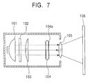
- Fig. 7 illustrates a conventional single-panel colour liquid crystal projector using such a colour-filter-combined liquid crystal display device (hereinafter referred to as a CF-combined liquid crystal display device).
- a CF-combined liquid crystal display device white light emitted from a source lamp 101 enters an ultraviolet and infrared cutting filter 102, where ultraviolet and infrared rays are absorbed, and then, enters a condenser lens 103.
- the light condensed by the condenser lens 103 is radiated onto a CF-combined liquid crystal display device 104 located in the rear of the condenser lens 103.
- the white light When passing through a liquid crystal layer (not shown) of the CF-combined liquid crystal device 104, the white light is modulated according to image signals applied to pixel electrodes on the CF-combined liquid crystal display device 104 provided for each of the primary colours (R, G and B).
- the white light is also colour-separated into a R light, a G light, and a B light by a colour filter 104a that is integrally formed with the CF-combined liquid crystal display device 104, transmitted through the CF-combined liquid crystal display device 104, and then, emitted.
- These modulated colored lights are condensed and synthesised by a projection lens 105 located in the rear of the CF-combined liquid crystal display device 104, and projected onto a screen 106 in an increased size.
- the aforesaid colour filter 104a in the CF-combined liquid crystal display device 104 is generally made of organic pigment. Since the colour filter of this pigment type absorbs light with a specific wavelength from incident light and transmits light with other wavelengths, the absorbed light is turned into heat and generates heat, or near ultraviolet rays, which are not cut by the ultraviolet-infrared cutting filter, are absorbed. Such heat generation or absorption deteriorates the colour filter itself, and also affects other constituents. In particular, since the colour filter using organic pigment originally has low resistance to weather, it is prone to fade with use, and colour quality of a display image is thereby degenerated. Accordingly, it is an important problem to restrict this heat generation or absorption, particularly in the future trend toward higher brightness.
- the colour filter using organic pigment shows a gentle spectral transmittance curve, and has a characteristic of transmitting therethrough lights with a wide range of wavelengths other than the specific wavelength. Therefore, the use of the colour filter of this type lowers colour purity of a formed image.
- the present invention has been made with such problems in view, and has as an object the provision of a projection colour image display apparatus having a simple structure that achieves colour separation with high purity and is resistant to fading.
- a projection colour image display apparatus comprising an optical modulating device, having pixel electrodes arranged in a required pattern corresponding to basic colours necessary for colour display, for modulating incident lights of the basic colours pixel by pixel according to image signals applied to the pixel electrodes, a colour filter located apart from the optical modulating device and composed of filter elements for the basic colours arranged in a pattern corresponding to the required pattern, and an imaging means for forming images of the filter elements in the colour filter on the optical modulating device.
- the colour filter may be a thin-film interference filter composed of layered inorganic thin films
- the optical modulating device may be a liquid crystal display device.
- the optical modulating device may be formed of, for example, an electrically controlled birefringent device that produces birefringence in incident lights through the application of voltage to pixel electrodes.
- the imaging means may be a beam condensing optical system including a first lens for focusing an incident parallel beam emitted from a colour filter to form an image, and a second lens for converting light from the image formed by the first lens into a parallel beam having a smaller beam diameter than that of the parallel beam incident on the first lens, and emitting the converted parallel beam.
- lights from the filter elements of the colour filter enter corresponding pixel electrodes of the optical modulating device each provided for basic colours, and form images thereon.
- the incident lights for the basic colours are modulated pixel by pixel according to image signals applied to the pixel electrodes.
- the imaging means is a beam condensing optical system for reducing the diameter of a parallel beam, images of the filter elements in the colour filter are projected and formed on the optical modulating device in a reduced size.
- Fig. 1 is a schematic structural view of an optical system in a projection colour image display apparatus according to an embodiment of the present invention.
- Fig. 2 is a view showing a layout pattern of filter elements for colours in a colour filter shown in Fig. 1.
- Fig. 3 is a cross-sectional view showing a structure and an operation of a liquid crystal display device shown in Fig. 1.
- Fig. 4 is a view showing the relationship between the liquid crystal alignment direction and the polarisation direction of incident light in the liquid crystal display device of Fig. 3.
- Fig. 5 is a view showing spectral transmittance characteristics of a thin-film interference colour filter and a pigment colour filter.
- Fig. 6 is a view showing another structure of a relay optical system for use in the projection colour image display apparatus of the present invention.
- Fig. 7 is a cross-sectional view showing the schematic structure of a liquid crystal display device in a conventional projection colour image display apparatus.
- Fig. 1 shows the structure of the principal part of a projection colour image display apparatus (a liquid crystal projector) according to an embodiment of the present invention.
- This apparatus comprises a colour filter 10, a relay optical system 11 composed of convex lenses 11a and 11b coaxially located in the rear of the colour filter 10, a liquid crystal display device 12 serving as a light valve located in the rear of the convex lens 11b, a polarising beam splitter (hereinafter abbreviated as PBS") 13 located between the convex lens 11b and the liquid crystal display device 12, a projection lens 14 having the optical axis intersecting the optical axis of the convex lenses 11a and 11b and located on the side of the PBS 13, and a screen 15 located opposed to the projection lens 14.
- PBS polarising beam splitter
- the liquid crystal display device 12 corresponds to the optical modulating device in the present invention
- the colour filter 10 corresponds to the colour filter in the present invention
- the relay optical system 11 consisting of the convex lenses 11a and 11b corresponds to the imaging means in the present invention.
- the colour filter 10 is composed of filter elements for colours R, G, and B that are regularly arranged, as shown in Fig. 2.
- Three primary colours R, G, and B correspond to basic colours necessary for colour display in the present invention.
- These filter elements are each, for example, a thin-film interference filter that is formed by laminating thin films of metal, a dielectric, or the like.
- each R element reflects B and G lights and transmits only R light therethrough
- each G element reflects R and B lights and transmits only G light therethrough
- each B element reflects R and G lights and transmits only B light therethrough.
- Such a thin-film interference filter can be formed by alternately laminating films having a high refractive index (for example, titanium dioxide (TiO 2 ) films) and films having a low refractive index (for example, silicon dioxide (SiO 2 ) films).
- the R, G, and B filter elements can be formed by repeating a thin film laminating process using well-known photolithography technology. In that case, the properties required of the filter elements can be easily obtained by appropriately setting, for example, the thickness and number of thin films to be laminated.
- the layout pattern of the R, G, and B filter elements is not limited to that shown in Fig. 2, and it may be an arbitrary layout pattern as long as it corresponds to the layout pattern of pixel electrodes in the liquid crystal display device 12.
- the PBS 13 is provided with a polarising separation plane 13a that has the property of transmitting p-polarized light and reflecting s-polarized light.
- the PBS 13 is located so that the polarising separation plane 13a forms about 45° with the optical axis of the relay optical system 11.
- the p-polarized component means linearly polarized light in which the oscillation direction of an electric vector of light incident on the polarising separation plane 13a is included in the incident plane (a plane including the normal to the polarising separation plane 13a and the wave normal (the travel direction of light)), and the s-polarized component means linearly polarized light in which the oscillation direction of an electric vector of light incident on the polarising separation plane 13a is orthogonal to the incident plane.
- the liquid crystal display device 12 is, for example, an optical modulating device of an electrically controlled birefringent (ECB) type, and has, for example, the structure shown in Fig. 3.
- the liquid crystal display device 12 comprises a pixel substrate 12c on which pixel electrodes 12a, 12b and so on are regularly formed, a counter substrate 12d located opposed to the front side (light incident side) of the pixel substrate 12c with a required spacing, a liquid crystal layer 12e sandwiched between the pixel substrate 12c and the counter electrode 12d, and a counter electrode 12f formed on the rear side (light emergent side) of the counter electrode 12d.
- the pixel electrodes 12a, 12b and so on are formed as reflecting electrodes each for reflecting incident light from the surface thereof.
- the layout pattern of the pixel electrodes 12a, 12b and so on in the liquid crystal display device 12 corresponds to the layout pattern of the filter elements (R, G, and B) in the colour filter 10. That is, for example, one filter element R in the colour filter 10 corresponds to one pixel electrode for R in the liquid crystal display device 12. This also applies to other filter elements.
- Regions among the pixel electrodes 12a, 12b and so on are black matrix sections that are provided with TFTs or the like respectively for the pixel electrodes to switch voltage application to the pixel electrodes, and they are each shielded from light by a film (not shown) of metal, such as aluminum, so that light leakage of the TFT is not caused by light radiation.
- the pixel electrodes 12a, 12b and so on are each assigned to colours (B, R, and G).
- an image signal voltage for one of the colours is applied to each pixel electrode, the alignment of liquid crystal molecules in a region of the liquid crystal layer 12e corresponding to the pixel electrode is changed, and the polarisation direction of light that passes through the region is thereby changed. That is, for example, as shown in Fig. 3, the alignment in a region of the liquid crystal layer 12e corresponding to the pixel electrode 12a, to which no voltage is applied, is parallel to the optical axis, and the alignment in a region corresponding to the pixel electrode 12b, to which voltage is applied, is orthogonal to the optical axis, provided an alignment direction A when voltage is applied is, as shown in Fig.
- White light radiated from a light source enters the colour filter 10 as parallel light.
- the filter elements in the colour filter 10 each separate the incident white light into lights of primary colours R, G, and B by reflecting light with specific wavelengths of the white light and transmitting light with other wavelengths therethrough.
- the parallel beam consisting of colour-separated lights enters the convex lens 11a in the relay optical system 11, is condensed and focused, and then, is converted again into a parallel beam by the convex lens 11b.
- the diameter of the parallel beam emitted from the convex lens 11b is f 2 /f 1 times that of the initial light beam.
- the parallel beam emitted from the convex lens 11b enters the PBS 13, and only a p-polarized component thereof transmits through the polarising plane 13a of the PBS 13 and enters the liquid crystal display device 12.
- pattern images which are reduced to f 2 /f 1 times the size of the filter elements in the colour filter 10, are formed by projection.
- the pattern of the images corresponds to the layout pattern of the pixel electrodes 12a, 12b and so on on the pixel substrate 12c (Fig. 3). That is, for example, a reduced image of one filter element R in the colour filter 10 is formed on the pixel electrode for R in the liquid crystal display device 12. This also applies to reduced images of other filter elements in the colour filter 10.
- the alignment direction of the liquid crystal is vertical in the liquid crystal layer 12e of the liquid crystal display device 12 when no voltage is applied to the pixel electrode, if voltage is applied, the alignment direction of the liquid crystal changes to the horizontal direction and birefringence of incident light arises. Therefore, the light incident on the liquid crystal display device 12 (p-polarized component) is modulated depending on the voltage applied to the pixel electrode, and an s-polarized component is thereby generated. The s-polarized component is reflected by the PBS 13, and enlarged and projected onto the screen 15 by the projection lens 14.
- Fig. 5 shows spectral transmittance characteristics of a colour filter of the thin-film interference type and a colour filter of the pigment type.
- G filter elements are given as an example.
- numerals 21 and 22 respectively denote spectral transmittance characteristics of the pigment colour filter and the thin-film interference colour filter.
- the horizontal axis represents the wavelength of light, and the vertical axis represents the spectral transmittance.
- a spectral transmittance curve of the pigment type 21 has a lower peak than that of the thin-film interference type 22, and is gently curved so that it extends to wavelength regions other than an objective transmission wavelength region. Moreover, the transmission band thereof is wide. Therefore, when the pigment-type colour filter is used, brightness and colour purity of a formed image are both low. On the other hand, since the spectral transmittance curve has a high peak and the edges of the transmission band are sharp in the thin-film interference type 22, only light with wavelengths in a specific region is allowed to be transmitted therethrough. Accordingly, when this colour filter of the thin-film interference type is used, since brightness and colour purity of a formed image are high, it is possible to produce a high-quality image display. In addition, since the thin-film interference type is formed of inorganic films as distinct from the pigment type formed of organic films, it does not fade and has high weather resistance and high durability.
- the colour filter is not integrated with the liquid crystal display device 12 and is separately located apart therefrom, and images of filter elements in the colour filter 10 are formed in a reduced size on the liquid crystal display device 12 through the relay optical system 11. Therefore, even if the size and pitch of the layout pattern of the filter elements in the colour filter 10 are relatively rough, images of the filter elements are projected in a reduced size onto corresponding pixel electrodes of the liquid crystal display device 12, and matched with a high-definition layout pattern of the pixel electrodes. That is, it is possible to accurately modulate respective colored lights by the pixel electrodes without increasing manufacturing accuracy of the colour filter 10, and to thereby achieve a high-definition image display.
- the colour filter 10 is separate from the liquid crystal display device 12, a liquid crystal display device manufactured for a monochrome apparatus may be used as the liquid crystal display device 12.
- the monochrome liquid crystal display device functions as if to be equipped with a colour filter, which makes it possible to display a high-definition colour image.
- the colour filter 10 is of a thin-film interference type in this embodiment, it does not generate heat due to absorption as distinct from the pigment type, has high weather resistance and high durability, and is resistant to fading.
- the relay optical system 11 in the aforesaid embodiment is of what is called a Keplerian type that employs the two convex lenses 11a and 11b, it may be of what is called a Galilean type that employs a convex lens 31 and a concave lens 32 as shown in Fig. 6.
- a virtual focus 33 of the convex lens 31 functions as a new virtual object point of the convex lens 32, and a parallel beam of a reduced diameter is emitted from the concave lens 32.
- the liquid crystal display device 12 is of a reflection type and light reflected therefrom is separated by the PBS 13 in this embodiment, the present invention is also applicable to a transmission-type liquid crystal display device.
- the PBS 13 is unnecessary, and the projection lens 14 and the screen 15 are placed in this order behind the liquid crystal display device 12.
- the liquid crystal display device 12 in this embodiment is an optical modulating device of an electrically controlled birefringent (ECB) type, it may be a liquid crystal display device of a reflected light intensity modulation type or a light scattering type.
- EBC electrically controlled birefringent
- liquid crystal display device in this embodiment has been described as an optical modulating device of an electrically controlled birefringent type, the present invention is not limited to this.
- Other devices that cause birefringence in incident light through the application of voltage for example, PLZT (lead lanthanum zirconate titanate) that is a transparent ceramic obtained by doping lead zirconate titanate with strontium), may be used.
- the colour filter 10 is not limited to the thin-film interference type, and may be of another type (for example, the conventional organic pigment type).
- a colour filter is placed apart from an optical modulating device, images of filter elements in the colour filter are formed on corresponding pixel electrodes for basic colours in the optical modulating device by causing lights from the filter elements to enter the pixel electrodes, and the incident lights for the basic colours are modulated pixel by pixel according to image signals applied to the pixel electrodes. Therefore, it is possible to produce a colour filter separately from an optical modulating device and to use the colour filter for colour image display. This provides the advantage of applying a monochrome optical modulating device to a colour optical modulating device. In addition, the degree of freedom of layout of optical elements is increased in manufacturing the apparatus.
- the colour filter is a thin-film interference filter formed by laminating inorganic thin films, it is possible to obtain a colour filter having a spectral transmittance characteristic in which the peak of transmittance is high and the edges of a transmission band are sharp. This makes it possible to display an image with high brightness and high colour purity.
- the colour filter of this type does not have a problem of heat generation due to absorption as distinct from a pigment-type colour filter, has high weather resistance and high durability, and is resistant to fading.
- images of filter elements in the colour filter are focused onto the optical modulating device through the use of a beam condensing optical system for reducing the diameter of a parallel beam, they are projected in a reduced size onto corresponding pixel electrodes in the optical modulating device. This enables a high-definition image display without increasing the definition of the colour filter. Consequently, it is possible to achieve a projection colour image display apparatus of high quality at low cost.
Landscapes
- Physics & Mathematics (AREA)
- General Physics & Mathematics (AREA)
- Optics & Photonics (AREA)
- Engineering & Computer Science (AREA)
- Multimedia (AREA)
- Signal Processing (AREA)
- Liquid Crystal (AREA)
- Projection Apparatus (AREA)
- Optical Filters (AREA)
Applications Claiming Priority (3)
| Application Number | Priority Date | Filing Date | Title |
|---|---|---|---|
| JP21834/97 | 1997-02-04 | ||
| JP2183497 | 1997-02-04 | ||
| JP9021834A JPH10221673A (ja) | 1997-02-04 | 1997-02-04 | 投射型カラー画像表示装置 |
Publications (2)
| Publication Number | Publication Date |
|---|---|
| EP0859522A2 true EP0859522A2 (de) | 1998-08-19 |
| EP0859522A3 EP0859522A3 (de) | 2002-07-03 |
Family
ID=12066111
Family Applications (1)
| Application Number | Title | Priority Date | Filing Date |
|---|---|---|---|
| EP98400232A Withdrawn EP0859522A3 (de) | 1997-02-04 | 1998-02-04 | Projektions-Farbbildanzeigevorrichtung |
Country Status (3)
| Country | Link |
|---|---|
| US (1) | US5902031A (de) |
| EP (1) | EP0859522A3 (de) |
| JP (1) | JPH10221673A (de) |
Cited By (2)
| Publication number | Priority date | Publication date | Assignee | Title |
|---|---|---|---|---|
| FR2857108A1 (fr) * | 2003-07-01 | 2005-01-07 | Thomson Licensing Sa | Dispositif d'affichage et moteur optique pour un tel dispositif |
| WO2004028168A3 (en) * | 2002-09-20 | 2006-03-16 | Koninkl Philips Electronics Nv | Projection device for projecting an image |
Families Citing this family (5)
| Publication number | Priority date | Publication date | Assignee | Title |
|---|---|---|---|---|
| JP3750303B2 (ja) * | 1997-09-11 | 2006-03-01 | ソニー株式会社 | 液晶表示装置 |
| JP3614001B2 (ja) * | 1997-12-03 | 2005-01-26 | セイコーエプソン株式会社 | 投影装置 |
| JPH11305192A (ja) * | 1998-04-27 | 1999-11-05 | Sony Corp | 光変調素子および画像投射表示装置 |
| JP2002287084A (ja) * | 2001-03-28 | 2002-10-03 | Fuji Photo Optical Co Ltd | 反射型液晶表示素子を用いた投写型画像表示装置 |
| TWI427616B (zh) * | 2009-10-01 | 2014-02-21 | Genesys Logic Inc | 光補償機制、光機裝置、顯示系統及其光補償之方法 |
Family Cites Families (4)
| Publication number | Priority date | Publication date | Assignee | Title |
|---|---|---|---|---|
| DE3880256T2 (de) * | 1987-10-21 | 1993-07-29 | Sharp Kk | Projektionsfarbanzeigegeraet. |
| GB2222923B (en) * | 1988-09-14 | 1992-09-23 | Marconi Gec Ltd | Display apparatus |
| FR2667972B1 (fr) * | 1990-10-12 | 1992-11-27 | Thomson Csf | Dispositif de visualisation d'images en couleurs. |
| JPH06167705A (ja) * | 1992-11-30 | 1994-06-14 | Sanyo Electric Co Ltd | 単板式液晶プロジェクター |
-
1997
- 1997-02-04 JP JP9021834A patent/JPH10221673A/ja active Pending
-
1998
- 1998-02-04 US US09/018,438 patent/US5902031A/en not_active Expired - Fee Related
- 1998-02-04 EP EP98400232A patent/EP0859522A3/de not_active Withdrawn
Cited By (3)
| Publication number | Priority date | Publication date | Assignee | Title |
|---|---|---|---|---|
| WO2004028168A3 (en) * | 2002-09-20 | 2006-03-16 | Koninkl Philips Electronics Nv | Projection device for projecting an image |
| FR2857108A1 (fr) * | 2003-07-01 | 2005-01-07 | Thomson Licensing Sa | Dispositif d'affichage et moteur optique pour un tel dispositif |
| WO2005006769A1 (en) * | 2003-07-01 | 2005-01-20 | Thomson Licensing | Display device and optical motor for such a device |
Also Published As
| Publication number | Publication date |
|---|---|
| JPH10221673A (ja) | 1998-08-21 |
| EP0859522A3 (de) | 2002-07-03 |
| US5902031A (en) | 1999-05-11 |
Similar Documents
| Publication | Publication Date | Title |
|---|---|---|
| US5798819A (en) | Projection-display apparatus and method providing improved brightness of projected color image | |
| JP3060049B2 (ja) | 画像投射装置 | |
| US5580142A (en) | Image forming apparatus and projector using the same | |
| JP4059066B2 (ja) | プロジェクタ | |
| US6330112B1 (en) | Optical modulator and image projection display apparatus | |
| US7255444B2 (en) | Optical unit and projection-type image display apparatus using the same | |
| US5726719A (en) | Projection-type color display device | |
| JPH11212023A5 (de) | ||
| US6089718A (en) | Projection display device | |
| EP1289312B1 (de) | Optischer Farbenteiler, optisches System zur Bildanzeige und Projektionsbildanzeigegerät | |
| US5902031A (en) | Projection color image display apparatus | |
| US8866977B2 (en) | Projector | |
| JP3554520B2 (ja) | 画像表示装置 | |
| EP1278381A2 (de) | Bildprojektionsgerät | |
| JP3491150B2 (ja) | プロジェクタ | |
| EP1762882B1 (de) | Wellenlängenselektiver Polarisationsstrahlteiler | |
| JPH09105900A (ja) | 光書込み式投写型ディスプレイ装置 | |
| JP2003279734A (ja) | 偏光子と液晶装置及び投射型表示装置 | |
| JP3708921B2 (ja) | 液晶プロジェクタ | |
| JPH0993598A (ja) | プロジェクタ装置 | |
| KR100257608B1 (ko) | 투사형 화상 표시 장치 | |
| KR100257609B1 (ko) | 투사형 화상 표시 장치 | |
| JP4141813B2 (ja) | 投射型表示装置 | |
| JPH11133414A (ja) | 投写型表示装置 | |
| JP3614164B2 (ja) | 投写型表示装置 |
Legal Events
| Date | Code | Title | Description |
|---|---|---|---|
| PUAI | Public reference made under article 153(3) epc to a published international application that has entered the european phase |
Free format text: ORIGINAL CODE: 0009012 |
|
| AK | Designated contracting states |
Kind code of ref document: A2 Designated state(s): AT BE CH DE DK ES FI FR GB GR IE IT LI LU MC NL PT SE |
|
| AX | Request for extension of the european patent |
Free format text: AL;LT;LV;MK;RO;SI |
|
| PUAL | Search report despatched |
Free format text: ORIGINAL CODE: 0009013 |
|
| AK | Designated contracting states |
Kind code of ref document: A3 Designated state(s): AT BE CH DE DK ES FI FR GB GR IE IT LI LU MC NL PT SE |
|
| AX | Request for extension of the european patent |
Free format text: AL;LT;LV;MK;RO;SI |
|
| AKX | Designation fees paid | ||
| REG | Reference to a national code |
Ref country code: DE Ref legal event code: 8566 |
|
| STAA | Information on the status of an ep patent application or granted ep patent |
Free format text: STATUS: THE APPLICATION IS DEEMED TO BE WITHDRAWN |
|
| 18D | Application deemed to be withdrawn |
Effective date: 20030104 |