EP0859243A1 - Laseridentifikationssystem - Google Patents
Laseridentifikationssystem Download PDFInfo
- Publication number
- EP0859243A1 EP0859243A1 EP97120818A EP97120818A EP0859243A1 EP 0859243 A1 EP0859243 A1 EP 0859243A1 EP 97120818 A EP97120818 A EP 97120818A EP 97120818 A EP97120818 A EP 97120818A EP 0859243 A1 EP0859243 A1 EP 0859243A1
- Authority
- EP
- European Patent Office
- Prior art keywords
- laser
- target device
- identification system
- soldier
- chopped
- Prior art date
- Legal status (The legal status is an assumption and is not a legal conclusion. Google has not performed a legal analysis and makes no representation as to the accuracy of the status listed.)
- Granted
Links
- 230000005855 radiation Effects 0.000 claims description 33
- 238000012790 confirmation Methods 0.000 claims description 11
- 230000008719 thickening Effects 0.000 claims description 6
- 238000005286 illumination Methods 0.000 claims description 5
- 239000000463 material Substances 0.000 claims description 4
- 230000002093 peripheral effect Effects 0.000 claims description 4
- 239000007787 solid Substances 0.000 claims description 3
- 238000011144 upstream manufacturing Methods 0.000 claims 3
- 230000003321 amplification Effects 0.000 claims 1
- 238000003199 nucleic acid amplification method Methods 0.000 claims 1
- 230000001105 regulatory effect Effects 0.000 claims 1
- 238000001514 detection method Methods 0.000 description 27
- 230000004297 night vision Effects 0.000 description 7
- 230000005540 biological transmission Effects 0.000 description 6
- 230000035945 sensitivity Effects 0.000 description 6
- 238000004088 simulation Methods 0.000 description 6
- 230000004044 response Effects 0.000 description 5
- 239000004065 semiconductor Substances 0.000 description 5
- 239000003990 capacitor Substances 0.000 description 4
- 230000000694 effects Effects 0.000 description 4
- 238000000034 method Methods 0.000 description 4
- 230000003287 optical effect Effects 0.000 description 4
- 230000006870 function Effects 0.000 description 3
- 239000011521 glass Substances 0.000 description 3
- 238000001208 nuclear magnetic resonance pulse sequence Methods 0.000 description 3
- 230000008569 process Effects 0.000 description 3
- 230000009471 action Effects 0.000 description 2
- 230000007613 environmental effect Effects 0.000 description 2
- 230000005484 gravity Effects 0.000 description 2
- 239000010453 quartz Substances 0.000 description 2
- VYPSYNLAJGMNEJ-UHFFFAOYSA-N silicon dioxide Inorganic materials O=[Si]=O VYPSYNLAJGMNEJ-UHFFFAOYSA-N 0.000 description 2
- 238000001228 spectrum Methods 0.000 description 2
- 238000011179 visual inspection Methods 0.000 description 2
- 229910001218 Gallium arsenide Inorganic materials 0.000 description 1
- 208000027418 Wounds and injury Diseases 0.000 description 1
- LNSPFAOULBTYBI-UHFFFAOYSA-N [O].C#C Chemical group [O].C#C LNSPFAOULBTYBI-UHFFFAOYSA-N 0.000 description 1
- 230000008859 change Effects 0.000 description 1
- 239000002800 charge carrier Substances 0.000 description 1
- 238000004891 communication Methods 0.000 description 1
- 239000013078 crystal Substances 0.000 description 1
- 230000002354 daily effect Effects 0.000 description 1
- 230000006378 damage Effects 0.000 description 1
- 230000001419 dependent effect Effects 0.000 description 1
- 238000010586 diagram Methods 0.000 description 1
- 230000005684 electric field Effects 0.000 description 1
- 238000011156 evaluation Methods 0.000 description 1
- 230000003203 everyday effect Effects 0.000 description 1
- 230000036039 immunity Effects 0.000 description 1
- 208000014674 injury Diseases 0.000 description 1
- 230000007774 longterm Effects 0.000 description 1
- 239000000203 mixture Substances 0.000 description 1
- BASFCYQUMIYNBI-UHFFFAOYSA-N platinum Chemical compound [Pt] BASFCYQUMIYNBI-UHFFFAOYSA-N 0.000 description 1
- 238000011896 sensitive detection Methods 0.000 description 1
- 230000003595 spectral effect Effects 0.000 description 1
- 230000036962 time dependent Effects 0.000 description 1
- 238000012549 training Methods 0.000 description 1
- 230000000007 visual effect Effects 0.000 description 1
Images



Classifications
-
- G—PHYSICS
- G01—MEASURING; TESTING
- G01S—RADIO DIRECTION-FINDING; RADIO NAVIGATION; DETERMINING DISTANCE OR VELOCITY BY USE OF RADIO WAVES; LOCATING OR PRESENCE-DETECTING BY USE OF THE REFLECTION OR RERADIATION OF RADIO WAVES; ANALOGOUS ARRANGEMENTS USING OTHER WAVES
- G01S17/00—Systems using the reflection or reradiation of electromagnetic waves other than radio waves, e.g. lidar systems
- G01S17/74—Systems using reradiation of electromagnetic waves other than radio waves, e.g. IFF, i.e. identification of friend or foe
Definitions
- the invention relates to military identification systems, in particular with lasers working identification systems.
- Lasers generally emit a highly collimated quasi-monochromatic light beam.
- Semiconductor lasers made of different materials record with their emission a light spectrum from the ultraviolet to the infrared range.
- Currently Available lasers are very reliable and are getting smaller and more powerful almost every day.
- the semiconductor chip of a GaAs diode laser for example, is extremely small in its dimensions, comparable to the size of a pin head (without consideration the power supply).
- Semiconductor lasers can be pulsed or continuously emitting be carried out. Modern, profit-generating laser media enable the appropriate Feed the generation of short pulses of a few nanoseconds a continuously emitting laser.
- Semiconductor lasers emitting in the infrared range are ideally suited for use in friend-foe detection systems.
- Light rays emitted by infrared diode lasers cannot be seen by the unarmed eye. Such rays of light are can only be made out by using special visual aids, e.g. B. Night vision glasses.
- infrared laser diode using the appropriate optics emitted light collimate into a sharply focused beam, which is ideal for illuminating point targets.
- collimated light rays infrared laser diodes have a beam diameter at a distance of 100m from about 5cm, which makes it possible to isolate almost every point target very precisely illuminate. Furthermore, due to the narrow radiation angle of the used Laser beams great security against countermeasures.
- lasers have the special feature to emit light in the form of a single, narrow, and nearly diffraction-limited beam.
- a 100 watt light bulb may emit significantly more light than a comparatively low-performing laser, but that's from the glowing Light emitted by wire is spatially and temporally incoherent, making it broad on the one hand has optical spectrum, on the other hand despite the relatively large area of the glowing Wire is emitted in a large solid angle.
- a high-quality lens can completely capture the light emitted by a laser and focus almost all of its optical power into a nearly diffraction-limited spot with a diameter that is on the order of a few micrometers.
- the optical power densities which can be achieved by focusing the light of a moderately powerful, continuously emitting diode laser of, for example, 25 mW light output, are more than 50 kW / cm 2 .
- the power density on an oxygen-acetylene flame is mentioned, which is approximately 1 kW / cm 2 .
- a friend-foe detection system needs a very good detection system.
- the base for a friend-foe detection system in this sense is an extremely sensitive detection system, even under difficult lighting conditions in open terrain Bushes works reliably.
- PIN photodiodes consist of a p as well an n-doped zone, both intrinsic material undoped by a zone are separated. These photodiodes are usually designed so that the majority the incident radiation is absorbed in the undoped intrinsic region, which ensures that all charge carriers generated by the light from the internal electrical field of the photodiode are detected and contribute to the photocurrent.
- a PIN photodiode compared to a PN photodiode also has a lower capacitance on, which makes the response time of a detection system very short.
- a short response time of the detector is ideal in friend-foe detection systems, which are based on the Transmission of high rates of short pulses.
- PIN photodiodes are due to their excellent stability against environmental influences as well as their usability in a wide temperature range good for use in friend-foe detection systems used in open terrain. Another important point for their application in such systems is a minimal influence of Sunlight on the detection system.
- Several manufacturers produce photodiodes directly on the surface of the chip attached special optical filters that are undesirable suppress spectral ranges. These filters can be used to create a Most of the light from the sun or other disturbing sources in the area, such as. to eliminate that of street lamps or moving lights. Long-term stability Modern PIN photodiodes ensure that there is no measurable drop in their sensitivity over their lifespan will occur.
- the light source emits a signal with a time course guaranteed by the accuracy of quartz oscillators, wherein the receiver is also equipped with quartz crystals of the corresponding frequencies is.
- quartz oscillators By using continuously emitting lasers, sensitivities become realized that cannot be reached with pulsed systems. These are with this one described invention in the nanowatt range. This makes it extremely effective Range allows and the implementation of a system that allows absolute security also of the unprotected eye and its usability through leaves, Fog and rain are not significantly affected.
- the "Continuous Wave Laser Battlefield Simulation System” (SIMLAS) of the The applicant uses lasers and light emitting diodes (LED light emitting diodes) for simulation weapons including but not limited to rifles, pistols, hand grenades, Tanks and landmines.
- the weapon is usually used by the soldier applied and their effect by a beam of light as realistic as possible shown, be it that of a rifle or pistol bullet, an exploding Hand grenade etc.
- All participants in such an exercise both people and objects such as B. tanks, planes, off-road vehicles, trucks, etc. are equipped with detectors, a possible weapon impact on the participant (such as a direct or almost hit).
- the laser light source sends, for example, a narrow infrared light beam, its divergence is only 0.2 mrad. This results in a beam diameter of after 100 m only approx. 4 cm, which is why this laser is used together with night vision devices as a target aid can be.
- the divergence can also be, for example, between 0.1 and 5 mrad or are between 0.2 and 2 mrad. Assembly and adjustment of the laser can be carried out permanently, that the system meets military standards regarding vibration resistance.
- the laser light beam used in SIMLAS is coded in this way modulates that both the person acting and the type of weapon used are unique can be identified.
- SIMLAS can simulate all training phases, including: (a) registration direct hit, nearly hit, injury, incapacity, etc .; (b) Identification of troops and their status; (c) Including all events Time and acting person; and (d) compilation of performance-related data individuals or groups.
- SIMLAS continuously emitting laser diodes are used.
- the light beam is in PCM and PPM encoded because these types of modulation high accuracy with high sensitivity and immunity against interference and noise.
- the mode of action of SIMLAS provides the technical basis of the friend-foe detection system according to the present Invention.
- “Soldiers of friendship” have a system device according to the invention mounted on the weapon for illuminating a target and carry on their bodies a belt device with sensors belonging to the system device in the sense of the invention, which perform detection tasks for various applications in any simulation scenarios in exercises and battles.
- the system device for illuminating the target sends a modulated light beam against the Another soldier's belt device sensors.
- the modulated light beam transmits a message or message in the form of a flexible protocol that depends on the required information as a data packet, for example between 4 and 400 bits long is coded, but preferably up to 200 bits.
- the friend-foe detection system based only on the transmission of preferably 16 bits each, while a friend-foe detection system with a simulation option might need 44 bits.
- the code is transmitted within 5 to 70 ms, depending on the number of bits to be transmitted.
- the sensor interprets the code, which is nominally in zones to identify the individual soldiers (16 bits), to identify the weapon used (4 bits) and to Transmission of the exact position (96 bits for all three determined by a GPS receiver Coordinates) is divided.
- the bit code can then be used to generate a highly encrypted Codes are used.
- the encoded signal can consist of information for identification: (a) the individual soldier, (b) a code that changes daily, (c) the battalion code and (d) the code of synchronization with a mixture of one time-dependent and a special code.
- the communication system therefore has one very large information bandwidth and is up to a transmission distance of 11.3 km extremely sensitive.
- the invention described here can preferably be briefly about distances corresponding to the visibility of a single soldier are applied, in general, however, it also serves to establish connections with soldiers who are beyond the specified distance.
- Fig. 1 shows how a detection system unit 1 according to the invention is such mounted on a weapon 2 is 1, that the center of gravity line 21 of the equipped with the laser device 1 gun intersects the laser device 1 itself.
- the laser device 1 ( FIG. 1 ) comprises a laser target illumination part 3 , a housing part 4 , in which, among other things, batteries necessary for operation are accommodated, and a mounting rail 5 which parts 3 and 4 together connects.
- Parts 3 and 4 have partially cylindrical sections that run parallel to one another so that a soldier can aim between them along a line of sight 22 ( FIG. 1 ).
- An end face of part 3 has a display window 31 in the manner of a miniature screen, which is used to display various pictograms for some useful information.
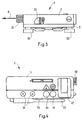
- the housing part 4 is provided with a light spot 41 , a light zone 42 , a mounting aid 43 for an antenna, two coax connections 44 , an operating button 45 , 46 and a switch 47 .
- the front part of part 3 has laser optics 32 which can emit a laser beam 11 .
- the mounting rail 5 can be provided with extensions 51 , 52 which facilitate mounting the device 1 on the weapon 2 .
- a lateral lever 33 can be provided in order to effect a change in the laser beam characteristic by inserting a hologram plate in such a way that the beam diameter is expanded in a ring-shaped manner or by points distributed in a ring-shaped manner at the target.
- FIG. 4 shows a housing part 4 with a pivotable rod antenna 53 and with a snap or fixing device 54 for this antenna 53 .
- a receiver optics 48 can be present on the front side of the housing part 4 .
- FIG. 5 shows a belt device 6 intended for the equipment of soldiers for combat purposes with a large number of electrical or electronic components.
- a belt device of this type is known, for example, from DE-OS-40 03 960 A1.
- the belt device 6 according to FIG. 5 carries sensors 61 , 62 , 63 , 64 , 65 , 66 , 67 , which are preferably equipped with a special electronic circuit.
- this belt device carries one or more LED transmitters 68 , 69 and a control unit 7, optionally with a battery.
- there is an obstacle, for example a bush 12 between the laser target lighting part 3 in the weapon of a first soldier A and the belt device of a second soldier B.
- the low voltage laser 8 in Fig. 6 is connected to a modulator 81, and for example, includes a laser diode 82, with their coupled feedback diode 83, an operational amplifier 84 and a transistor 85 as well as some resistors 86, 87 and 88.
- the anode of the diode 82 and the cathode of the diode 83 are connected together to a voltage source 89 , for example a battery of 3 to 5 volts.
- the cathode of diode 82 is connected to ground via the series connection of resistor 86 and the emitter-collector path of transistor 85 .
- the amplifier 84 with the resistor 87 connected downstream is inserted between the anode of the diode 83 and the base of the transistor 85 .
- the base of transistor 85 which forms the modulation input of the circuit, is connected to ground via resistor 88 .
- a reference potential can of course also serve as earth.
- the modulator comprises a circuit 81 which not only effects a coding function, but also a chopper function or chopper function in order to include a light signal of the (carrier) frequency ft before coding, which takes place at a bit rate of the frequency fd to chop a chopper frequency fz.
- the sensors 61 to 67 according to FIG. 5 contain a sensor circuit 9 according to FIG. 7 .
- the circuit 9 comprises, for example, a detector diode 91 , the cathode of which is connected on the one hand to the input of an amplifier 92 and on the other hand via a coil 93 to the one connection of a capacitor 94 .
- the output of the amplifier 92 is connected via an integrator filter 95 to a microprocessor 96 , the output signals of which are fed to the control unit 7 via cables.
- the friend-foe detection system of the present invention operates under two different environmental conditions depending on whether the target soldier is in open terrain or under cover. If, in a scenario with open terrain, a soldier A wants to identify a soldier B who is not in cover (in FIG. 5 , this would be without bush 12 ), he puts his laser-aiming device 1 mounted on the weapon into operation and " shoots "Soldier B with a laser beam 11 from the laser target illumination device 1 . A coded message 13 transported by the laser beam 11 requires soldier B to identify himself. A belt device 6 on soldier B receives the coded message 13 , which is composed of a signal from soldier A comprising, for example, 116 bits. A sensor, for example 63 on the belt device 6 from soldier B, recognizes the 116-bit signal.
- the confirmation code can be freely selected by the unit using the system. For example, it can consist of the name of Soldier B , the battalion, or any other term.
- soldier A is not only equipped with a laser transmitter 3 , but also has a laser receiver, optionally accommodated in part 4 , with a receiver optics 48 , which is mounted parallel to the laser transmitter, that is to say part 3 .
- the laser receiver now receives diffuse light from soldier B emitted by LED transmitter 68 .
- Soldier A sends an identification code until he receives Confirmation from Soldier B. If soldier B belongs to his own party, soldier A sees a red alarm signal in red dot 41 and / or in illuminated zone 42 , which prohibits him from fighting soldier B. This alarm signal appears in the system in such a way that it can only be seen by soldier A and not by the enemy.
- soldier A receives the confirmation signal for example via the Ermpfticianeroptik 48 in LED-receiver 49 of his device 1, an appropriate target illumination device 3 of the laser device 1 of soldier B is not used as an infrared transmitter to return to the confirmation signal to soldier A, because the laser target illuminator 3 emits a beam of light that is focused too sharply.
- This narrow beam of light preferably oriented at an angle of approximately 0.5 mrad, could not send the confirmation signal back to soldier A , since soldier B does not necessarily know the position of soldier A.
- a high-performance LED transmitter 68 LED light Emitting diode
- This LED transmitter 68 emits its light output in a much larger solid angle, which is why soldier B's confirmation can be received by soldier A under all circumstances. As long as soldier A can see soldier B, he will be able to receive the confirmation signal.
- the weapon 1 Since the fighting is increasingly taking place in poor lighting conditions, it is becoming increasingly common to equip soldiers taking part in the fighting with night vision goggles. If this is the case, the weapon 1 is usually guided by the soldier in the hip stop. The observation and aiming process takes place along the laser beam 11 , which is visible through night vision glasses (not shown). As a result of the hip position of the weapon 1 , the red alarm signal ( 41 and / or 42) is not visible to the soldier carrying the weapon 1 . However, since the laser target illumination device 3 is controlled by a microprocessor, it is easily possible to alternately switch the laser beam 11 on and off instead of or in addition to the red alarm signal. The soldier equipped with night vision goggles can quickly and easily record the alarm signal via the laser beam and thus identify the illuminated soldier as belonging to his own party.
- soldier A can only partially see soldier B's body. Soldier A shoots again with laser beam 11 as described above.
- the belt device 6 from soldier B will nevertheless detect the laser beam from soldier A because the overall system has sufficient sensitivity for this type of application, for example in that the sensors 61, 62, 63, .... are each equipped with special electronics, which can be powered by a common battery or possibly also by a single small battery.
- the main problem is that soldier B's LED transmitter 68 can be completely shielded by bush 12 and soldier A does not receive soldier B's response. Soldier A can only receive light coming directly from LED transmitter 68 because the light is emitted diffusely and not in a directional manner.
- soldier A receives no confirmation within a period of time Ta of, for example, 100 ms after the laser beam has been emitted, but soldier B is obviously able to receive messages from soldier A , soldier B is given a second chance by sending out a pulse sequence via an the belt device 6 attached radio unit 71 , which may include a radio transmitter or radio transceiver, to transmit a confirmation.
- Radio unit 71 which may include a radio transmitter or radio transceiver, to transmit a confirmation.
- Soldier A can receive this radio signal under all conceivable circumstances, but because of its vulnerability to enemy countermeasures, it should only be used if other means fail. Enemy forces could also send out their own soldiers by sending out such radio signals. If soldier B is an enemy, no response to the query made by soldier A's laser beam will be given in either of the scenarios described above.
- the time period Tb can be, for example, between 1 ms and 1 s, but is preferably 100 ms, and Tc can be selected to be approximately equal to or greater than 0.1 ms, preferably approximately 1 ms or greater, for this pulse wave.
- the radio unit 72 can also comprise a radio transmitter or a radio transceiver. This pulse sequence can be received over a distance of several kilometers under all conceivable circumstances.
- the system will identify the illuminated target as an enemy object. A total of 200 ms is required for this process. If soldier A wears night vision goggles, he will see through the night vision goggles the continuously emitted laser beam that identifies an illuminated soldier as an enemy.
- the sensors 61 , 62 , 63 , ... are preferably designed in the form of round disks, with a relatively high thickness such that they are laser beam sensitive not only on the surface but also on the side, that is to say on the periphery of the disk .
- the detector 91 FIG. 7
- the laser beam is chopped so that the detector 91 detects intermittent radiation, which it converts into an alternating current of the same frequency fz with the aid of the resonance circuit formed by the coil 93 and the capacitor 94 .
- the resulting AC voltage at the input of amplifier 92 is amplified very strongly by the latter.
- the output signal of the amplifier 92 is fed to the integrator filter 95 , which emits the coded signals to the microprocessor 96 for evaluation. Signals evaluated from this are then supplied by the microprocessor 96 to the control unit 7 .
- the pulse width of the emitted chopped laser pulses is, for example, between 10 ns and 100 ⁇ s and preferably between 0.1 and 10 ⁇ s.
- the width of an information bit pulse preferably corresponds to the width of a number of 3 to 50 chopped laser pulses.
- a lever (not shown) can also be used to trigger the laser device instead of one of the control buttons 45 or 46 .
- the upper part of the laser device preferably forms two semi-cylindrical parallel chambers, the gap between these chambers unobstructed view of the target allowed. Since this gap is wide enough, in a further embodiment of the invention Illuminated dot just to be placed laterally in this gap, preferably in End area of the gap where the light beam is emitted, such that the soldier can see the target and this red dot at the same time.
- the laser device preferably emits light at a wavelength in the range between 780 and 905 nm, for example from 820 nm, for example with an output power of the order of 50 mW.
- the laser light source is operated with the holographic grating, whereby the emerging light beam can have a divergence of, for example, 10 mrad the range is approximately 2 km, without holographic grating due to the reduced divergence of 0.2 mrad, however, more than 10 km.
- the aiming process is at distances of less easier than 2 km through the inserted holographic grating.
- FIG. 8 shows the inner area of a capsule-shaped housing 610 of a sensor 61 , 62 , 63, ... ( FIG. 5 ) and FIG. 9 shows a section through the line IX-IX in FIG. 8 .
- the housing 610 has a preferably flat base 611 and an annular wall 612 . Inside, the housing 610 has four extensions 613 , 614 , 615 and 616 ( FIG. 8 ) with threaded holes for fastening a board 617 , which can be designed as a printed circuit board.
- the housing 610 is provided with a peripheral thickening 618 , which acts like a toroidal magnifying glass or converging lens for the incident laser radiation 619 , 620 , because the housing material is transparent or light-conducting for the laser radiation used.
- a peripheral thickening 618 acts like a toroidal magnifying glass or converging lens for the incident laser radiation 619 , 620 , because the housing material is transparent or light-conducting for the laser radiation used.
- the circuit board 617 three fastening elements 621 , 622 , 623 are preferably arranged, which extend relatively far into the inner region of the housing and hold there a printed circuit board 624 , which has a plurality of photosensors 625 , 626 , 627 , 628 and a microprocessor 629 or possibly only wears a discriminator.
- the fastening elements 621 , 622 , 623 can at the same time serve as electrical connections in order to conduct signals which have already been discriminated against via lines to
- the photosensors 625 , 626 , ... are arranged in the interior of the housing in such a way that their sensitive sides lie flat against the inner, preferably cylindrical, ring-shaped wall parts, which are located between the extensions 613 , 614 , 615 and 616 , to allow the received through to be able to detect the thickening of the laser radiation.
- the sensitive side of the printed circuit board 624 there is at least one further photosensor 630 , the sensitive side of which is directed towards the bottom 611 of the housing and is therefore suitable for the detection of laser beams 631 , 632 which are incident with a greater inclination to the surface of the bottom 611 than that Laser beams 620 and 619 , which propagate almost parallel to this floor area.
- the housing 610 preferably also houses an individual preamplifier 92 and an integrator filter 95 in order to obtain an alternating electrical signal as individual means from a received chopped laser radiation and to supply the already discriminated signals to the control unit 7 via lines.
- the coil 93 and / or the capacitor 94 can be accommodated or integrated in the printed circuit board 624 , which form the resonance circuit as sensor means.
- the discriminator and / or the microprocessor can be designed to filter out only signals with an expected coding from the received laser radiation.
- the sensors according to FIGS. 8 and 9 are consequently designed in the form of round disks with the diameter / thickness ratio resulting from the figure.
- the incident laser radiation can be reflected in the body of soldier B and can reach the radiation-sensitive side of the photosensor 625 laterally, for example as laser radiation 619 or 620 ( FIG. 9 ), through the peripheral thickening 618 .
- the housing 610 can be opaque to normal light, for example in color or black.
Landscapes
- Physics & Mathematics (AREA)
- Electromagnetism (AREA)
- Engineering & Computer Science (AREA)
- Computer Networks & Wireless Communication (AREA)
- General Physics & Mathematics (AREA)
- Radar, Positioning & Navigation (AREA)
- Remote Sensing (AREA)
- Optical Radar Systems And Details Thereof (AREA)
Abstract
Description

- Fig. 1
- zeigt ein auf einer Waffe montiertes Systemgerät nach der Erfindung.
- Fig. 2
- zeigt die rückseitige Ansicht eines Systemgeräts nach Fig. 1.
- Fig. 3
- zeigt die linksseitige Ansicht des Systemgeräts nach Fig. 1.
- Fig. 4
- zeigt die rechtsseitige Ansicht des Systemgeräts nach Fig. 1.
- Fig. 5
- zeigt eine schematische Darstellung zur Erläuterung der Arbeitsweise einer mit Sensoren ausgerüsteten Gurtvorrichtung des erfindungsgemässen Erkennungssystems, insbesondere im Fall eines teilweise verdeckten Ziels.
- Fig. 6
- zeigt eine schematische Darstellung eines bevorzugten Niederspannungs-Lasers, insbesondere zur Verwendung in einem Laser-Zielbeleuchtungsteil des erfindungsgemässen Systemgeräts.
- Fig. 7
- zeigt ein Blockschaltbild einer Sensorschaltung für die Sensoren einer solchen Gurtvorrichtung.
- Fig. 8
- zeigt den inneren Bereich eines kapselförmigen Gehäuses eines Sensors und
- Fig. 9
- einen Schnitt durch die Linie IX - IX in Fig. 8.
- 1
- Erkennungs-Systemgerät
- 11
- Laser-Strahl
- 12
- Busch
- 13
- codierte Nachricht
- 2
- Waffe
- 21
- Schwerpunktlinie
- 22
- Visierlinie
- 3
- Laser-Zielbeleuchtungsteil
- 31
- Display-Fenster
- 32
- Laser-Optik
- 33
- Hebel
- 4
- Gehäuseteil
- 41
- Leuchtpunkt
- 42
- Leuchtzone
- 43
- Befestigungshilfe
- 44
- Koaxanschlüsse
- 45
- Bedienungsknopf
- 46
- Bedienungsknopf
- 47
- Schalter
- 48
- Empfängeroptik
- 49
- LED-Empfänger
- 5
- Montierschiene
- 51,52
- Erweiterungen
- 53
- Stabantenne
- 54
- Schnapp- oder Fixiereinrichtung
- 6
- Gurtvorrichtung
- 61-67
- Sensoren
- 68
- LED-Sender
- 69
- LED-Sender
- 610
- Gehäuse
- 611
- Boden
- 612
- ringförmige Wand
- 613-616
- Erweiterungen
- 617
- Platine
- 618
- peripherische Verdickung
- 619
- Laserstrahlung
- 620
- Laserstrahlung
- 621-623
- Befestigungselemente
- 624
- Printplatte
- 625-628
- Photosensoren
- 629
- Mikroprozessor
- 630
- Photosensor
- 631
- Laserstrahlung
- 632
- Laserstrahlung
- 7
- Steuereinheit
- 71
- Funkeinheit
- 72
- Funkeinheit
- 8
- Niederspannungslaser
- 81
- Modulator
- 82
- Laserdiode
- 83
- Rückkopplungsdiode
- 84
- Operationsverstärker
- 85
- Transistor
- 86-88
- Widerstände
- 89
- Spannungsquelle
- 9
- Sensorschaltung
- 91
- Detektor-Diode
- 92
- Verstärker
- 93
- Spule
- 94
- Kondensator
- 95
- Integrator-Filter
- 96
- Mikroprozessor
Claims (12)
- Laseridentifikationssystem mit mindestens einem Lasergerät zur Identifizierung von wenigstens einer Zielvorrichtung, wobei das Lasergerät ausgebildet ist, um eine codierte Laserstrahlung auszusenden, und wobei die Zielvorrichtung Sensor-Mittel zur Detektierung dieser Laser-Strahlung und Umwandlung derselben in elektrische Signale aufweist, die einem Diskriminator zugeführt werden, sowie Sender-Mittel umfasst, um nach Massgabe von im Diskriminator getroffenen Entscheidungen Meldungen an Empfänger-Mittel, die sich innerhalb oder ausserhalb des Lasergeräts befinden, zurückzusenden,
dadurch gekennzeichnet,dass das Lasergerät ausgestaltet ist, um eine eng gebündelte Laserstrahlung auszusenden, und Zerhacker-Mittel (81) umfasst, um eine Laser-Strahlung (11) auszusenden, die nicht nur codiert, sondern auch mit einer vorgegebenen Frequenz gechoppt ist, unddass die Sensor-Mittel (61, ... 67) der Zielvorrichtung (6) Mittel umfassen, um aus der empfangenen gechoppten Laser-Strahlung ein alternierendes elektrisches Signal zu gewinnen, das einem Vorverstärker (92) zugeführt wird, der dem Diskriminator (96) vorgeschaltet ist. - Laseridentifikationssystem nach Anspruch 1,
dadurch gekennzeichnet,dass die Sender-Mittel (68; 69) der Zielvorrichtung (6) ausgebildet sind, um eine Laser-Strahlung in einem grossen Raumwinkel zu senden, und weitere Zerhacker-Mittel aufweist um eine Laser-Strahlung auszusenden, die nicht nur codiert, sondern auch mit einer vorgegebenen Frequenz gechoppt ist, unddass das Lasergerät einen weiteren Diskriminator sowie Sensor-Mittel umfasst, um aus der empfangenen gechoppten Laser-Strahlung ein alternierendes elektrisches Signal zu gewinnen, das einem weiteren Vorverstärker zugeführt wird, der diesem Diskriminator vorgeschaltet ist. - Laseridentifikationssystem nach Anspruch 1 oder 2,
dadurch gekennzeichnet,dass die Sensor-Mittel des Lasergeräts und/oder der Zielvorrichtung einen Resonanzkreis (93, 94) umfassen, der gegebenenfalls auf die Chopper-Frequenz der empfangenen Laserstrahlung abgestimmt oder geregelt werden kann. - Laseridentifikationssystem nach einem der Ansprüche 1 bis 3,
dadurch gekennzeichnet, dassder Verstärkungsgrad des Vorverstäkers (92) des Lasergeräts und/oder der Zielvorrichtung für den Bereich der entsprechenden Chopper-Frequenz optimiert ist. - Laseridentifikationssystem nach einem der Ansprüche 1 bis 4,
dadurch gekennzeichnet, dassdas Lasergerät und die Zielvorrichtung je einen Mikroprozessor und eine Funkeinheit (72, 71) aufweisen, derart, dass das Lasergerät, wenn es innerhalb einer Zeitspanne Ta nach Aussendung eines gebündelten codierten Laserstrahls keine Rückmeldung von der Zielvorrichtung erhält, einen weiteren Laserstrahl mit einer anderen Codierung sendet, die veranlasst, dass die Funkeinheit der Zielvorrichtung eine Bestätigung übermittelt, die von der Funkeinheit des Lasergeräts empfangen werden kann. - Laseridentifikationssystem nach Anspruch 5,
dadurch gekennzeichnet, dassdas Lasergerät, wenn es innerhalb einer Zeitspanne Tb nach Aussendung eines gebündelten Laserstrahls mit der zweiten Codierung keine Rückmeldung von der Zielvorrichtung erhält, eine Meldung der Dauer Tc über seine eigene Funkeinheit sendet in Erwartung einer Bestätigung via Funk von der Zielvorrichtung. - Laseridentifikationssystem nach einem der Ansprüche 1 bis 6,
dadurch gekennzeichnet, dassder modulierte Lichtstrahl Meldungen in Form eines flexiblen Protokolls übermittelt, das in Abhängigkeit von der benötigten Information als ein zwischen 4 und 200 bit langes Datenpaket codiert ist, wobei vorzugsweise der Code je nach der zu übertragenden Anzahl von Bits innerhalb von 5 bis 70 ms übermittelt wird. - Laseridentifikationssystem nach einem der Ansprüche 1 bis 6,
dadurch gekennzeichnet, dassdie Breite der ausgestrahlten gechoppten Laserimpulse zwischen 0.1 und 10 µs liegt, unddass die Breite eines Informations-Bit-Impulses vorzugsweise der Breite einer Anzahl von 3 bis 50 gechoppten Laserimpulse entspricht. - Lasergerät für ein Laseridentifikationssystem nach einem der Ansprüche 1 bis 8, dadurch gekennzeichnet, dassdas Lasergerät (1) auf einer Waffe (2) montierbar ist und einen Laser-Zielbeleuchtungsteil (3) aufweist, das ausgestaltet ist, um eine eng gebündelte Laserstrahlung (11) auszusenden, sowie Zerhacker-Mittel (81) umfasst, um eine Laser-Strahlung (11) auszusenden, die nicht nur codiert, sondern auch mit einer vorgegebenen Frequenz gechoppt ist.
- Zielvorrichtung für ein Laseridentifikationssystem nach einem der Ansprüche 1 bis 8,
dadurch gekennzeichnet, dassdie Zielvorrichtung (6) eine tragbare Gurtvorrichtung mit Sensor-Mitteln (61, 62, 63, ...) ist,die Abstimm-Mittel umfassen, um aus der empfangenen gechoppten Laser-Strahlung (11) ein alternierendes elektrisches Signal zu gewinnen, das einem einem Diskriminator (95) vorgeschalteten Vorverstärker (92) zugeführt wird. - Sensor für eine Gurtvorrichtung nach Anspruch 10,
dadurch gekennzeichnet, dassder Sensor ein kapselförmiges Gehäuse (610) mit einem Boden (611) und einer ringförmigen Wand (612) umfasst, dass das Gehäuse (610) wenigstens teilweise aus einem für die verwendete Laserstrahlung transparenten bzw. lichtleitenden Material ausgestaltet und mit einer peripherischen Verdickung (618) versehen ist, die in der Art einer Sammellinse für die einfallende Laserstrahlung (619, 620) wirkt, und dass Photosensoren (625, 626, ...) derart im Innern des Gehäuses angeordnet sind, dass ihre für die Laserstrahlung empfindlichen Seiten jeweils an innenseitigen vorzugsweise zylindrischen ringförmigen Wandpartien des Gehäuses anliegen, um eine durch die Verdickung geführte Laserstrahlung detektieren zu können. - Sensor nach Anspruch 11,
dadurch gekennzeichnet, dassin diesem Gehäuse nebst individuelle Mittel, um aus einer empfangenen gechoppten Laser-Strahlung ein alternierendes elektrisches Signal zu gewinnen, auch ein individueller Vorverstärker und ein Diskriminator untergebracht sind, derart dass bereits diskriminierte Signale über Leitungen an eine Steuereinheit (7) Zentralstelle geführt werden.
Priority Applications (5)
| Application Number | Priority Date | Filing Date | Title |
|---|---|---|---|
| AU52134/98A AU720331B2 (en) | 1997-02-18 | 1998-01-20 | Laser identification system |
| CA 2223975 CA2223975C (en) | 1997-02-18 | 1998-01-21 | Laser identification system |
| US09/019,424 US6174169B1 (en) | 1997-11-27 | 1998-02-05 | Laser identification system |
| JP03581198A JP4125813B2 (ja) | 1997-02-18 | 1998-02-18 | レーザー識別システム |
| US09/710,176 US6439892B1 (en) | 1997-02-18 | 2000-11-09 | Laser identification system |
Applications Claiming Priority (2)
| Application Number | Priority Date | Filing Date | Title |
|---|---|---|---|
| US3805197P | 1997-02-18 | 1997-02-18 | |
| US38051P | 1997-02-18 |
Publications (2)
| Publication Number | Publication Date |
|---|---|
| EP0859243A1 true EP0859243A1 (de) | 1998-08-19 |
| EP0859243B1 EP0859243B1 (de) | 2003-08-27 |
Family
ID=21897847
Family Applications (1)
| Application Number | Title | Priority Date | Filing Date |
|---|---|---|---|
| EP97120818A Expired - Lifetime EP0859243B1 (de) | 1997-02-18 | 1997-11-27 | Laseridentifikationssystem |
Country Status (2)
| Country | Link |
|---|---|
| EP (1) | EP0859243B1 (de) |
| DE (1) | DE59710657D1 (de) |
Cited By (7)
| Publication number | Priority date | Publication date | Assignee | Title |
|---|---|---|---|---|
| EP1154283A1 (de) * | 2000-05-12 | 2001-11-14 | Oerlikon Contraves Ag | Interrogations-und Respondersystem |
| EP1154221A1 (de) | 2000-05-12 | 2001-11-14 | Oerlikon Contraves Ag | Simulationssystem |
| EP1154220A1 (de) | 2000-05-12 | 2001-11-14 | Oerlikon Contraves Ag | Schiedsrichter- und Soldateninterface |
| US6450816B1 (en) | 1998-03-09 | 2002-09-17 | Oerlikon Contraves Ag | Identification system |
| EP1632744A1 (de) | 2004-09-07 | 2006-03-08 | Saab Ab | Simulationssystem |
| CN103776298A (zh) * | 2014-02-24 | 2014-05-07 | 李响 | 模拟射击训练系统 |
| CN116598870A (zh) * | 2023-04-28 | 2023-08-15 | 中国科学院空天信息创新研究院 | 一种碟片增益介质结构的激光器组件 |
Citations (4)
| Publication number | Priority date | Publication date | Assignee | Title |
|---|---|---|---|---|
| DE2215463A1 (de) * | 1972-03-29 | 1973-10-11 | Precitronic | Identifizierungs- und signaluebertragungssystem zur freund/feind-erkennung mittels laserlicht ueber raumfest stabilisierte einrichtungen |
| EP0187086A1 (de) * | 1984-12-14 | 1986-07-09 | Thomson-Csf | Verfahren zur Freund-oder-Feind-Abfrage und Vorrichtung zur Durchführung dieses Verfahrens |
| DE4003960A1 (de) * | 1989-02-09 | 1990-08-16 | Autoflug Gmbh | Lasererfassbare ausruestung fuer personen |
| US4983021A (en) * | 1988-08-10 | 1991-01-08 | Fergason James L | Modulated retroreflector system |
Family Cites Families (1)
| Publication number | Priority date | Publication date | Assignee | Title |
|---|---|---|---|---|
| DE3113154A1 (de) * | 1981-04-01 | 1982-12-02 | Precitronic Gesellschaft für Feinmechanik und Electronic mbH, 2000 Hamburg | "system zur optronischen dateneingabe in laser-nachrichtengeraeten" |
-
1997
- 1997-11-27 EP EP97120818A patent/EP0859243B1/de not_active Expired - Lifetime
- 1997-11-27 DE DE59710657T patent/DE59710657D1/de not_active Expired - Lifetime
Patent Citations (4)
| Publication number | Priority date | Publication date | Assignee | Title |
|---|---|---|---|---|
| DE2215463A1 (de) * | 1972-03-29 | 1973-10-11 | Precitronic | Identifizierungs- und signaluebertragungssystem zur freund/feind-erkennung mittels laserlicht ueber raumfest stabilisierte einrichtungen |
| EP0187086A1 (de) * | 1984-12-14 | 1986-07-09 | Thomson-Csf | Verfahren zur Freund-oder-Feind-Abfrage und Vorrichtung zur Durchführung dieses Verfahrens |
| US4983021A (en) * | 1988-08-10 | 1991-01-08 | Fergason James L | Modulated retroreflector system |
| DE4003960A1 (de) * | 1989-02-09 | 1990-08-16 | Autoflug Gmbh | Lasererfassbare ausruestung fuer personen |
Cited By (12)
| Publication number | Priority date | Publication date | Assignee | Title |
|---|---|---|---|---|
| US6450816B1 (en) | 1998-03-09 | 2002-09-17 | Oerlikon Contraves Ag | Identification system |
| EP1154283A1 (de) * | 2000-05-12 | 2001-11-14 | Oerlikon Contraves Ag | Interrogations-und Respondersystem |
| EP1154221A1 (de) | 2000-05-12 | 2001-11-14 | Oerlikon Contraves Ag | Simulationssystem |
| EP1154220A1 (de) | 2000-05-12 | 2001-11-14 | Oerlikon Contraves Ag | Schiedsrichter- und Soldateninterface |
| US6398555B1 (en) | 2000-05-12 | 2002-06-04 | Oerlikon Contraves Ag | Simulation system |
| SG100642A1 (en) * | 2000-05-12 | 2003-12-26 | Contraves Ag | Umpire and soldier interface |
| US6914518B1 (en) | 2000-05-12 | 2005-07-05 | Ruag Electronics | Interrogation and responder system for identifying a target |
| SG112801A1 (en) * | 2000-05-12 | 2005-07-28 | Contraves Ag | Interrogation and responder system |
| EP1632744A1 (de) | 2004-09-07 | 2006-03-08 | Saab Ab | Simulationssystem |
| CN103776298A (zh) * | 2014-02-24 | 2014-05-07 | 李响 | 模拟射击训练系统 |
| CN103776298B (zh) * | 2014-02-24 | 2015-12-09 | 张臣 | 模拟射击训练系统 |
| CN116598870A (zh) * | 2023-04-28 | 2023-08-15 | 中国科学院空天信息创新研究院 | 一种碟片增益介质结构的激光器组件 |
Also Published As
| Publication number | Publication date |
|---|---|
| EP0859243B1 (de) | 2003-08-27 |
| DE59710657D1 (de) | 2003-10-02 |
Similar Documents
| Publication | Publication Date | Title |
|---|---|---|
| EP0945697B1 (de) | Identifikationssystem | |
| US6439892B1 (en) | Laser identification system | |
| DE3688151T2 (de) | System zur bestimmung der position eines bewegten ziels. | |
| EP0836068A1 (de) | Gefechts-Kommunikationssystem | |
| US5299227A (en) | Individual beacon identification system | |
| DE3024247C2 (de) | ||
| DE4444636A1 (de) | Waffensystem für einen Blendlaser | |
| DE3822054A1 (de) | Uebungseinrichtung fuer handfeuerwaffen, wie revolver und pistolen | |
| EP0859243B1 (de) | Laseridentifikationssystem | |
| DE102017218683A1 (de) | Fahrzeugbasiertes Lidar-System | |
| DE10354714A1 (de) | Fahrzeugscheinwerfer und Verfahren zum Betreiben eines Fahrzeugscheinwerfers | |
| DE60211074T2 (de) | Laserwaffe und Zielsystem dafür | |
| DE4225074C1 (de) | Vorrichtung zur Steuerung des Verschlusses einer von einer Lichtquelle mit Licht beaufschlagten CCD-Kamera | |
| DE69726812T2 (de) | Zielsuchkopf eines Flugkörpers | |
| DE2824311C2 (de) | Justieranordnung zur Ausrichtung einer Gruppe zyklisch geschalteter Lichtsender oder Lichtempfänger | |
| EP1154221B1 (de) | System und Verfahren zur Simulation von Schüssen | |
| EP1130351A2 (de) | Vorrichtung zum Ermitteln der Lage und/oder Bewegung einer Waffe sowie Sicherheitsvorrichtung für eine Schusswaffe | |
| EP1645833B1 (de) | Visiervorrichtung für eine Schusswaffe und Schusswaffe mit einer Montagemöglichkeit für eine Visiervorrichtung | |
| AU720331B2 (en) | Laser identification system | |
| WO2023143715A1 (de) | Flächensensor zum erfassen eines einfallenden lichtsignals | |
| CH694672A5 (de) | System mit einem Interrogations- und Respondersystem. | |
| DE102012100746B4 (de) | Sendeeinheit für einen optischen Sensor | |
| EP3882561B1 (de) | Verfahren zum schützen eines fahrzeugs durch eine freund-feind-erkennung | |
| EP3882560B1 (de) | Verfahren zum schützen eines fahrzeugs durch eine freund-feind-erkennung | |
| EP2570821A1 (de) | Vorrichtung und Verfahren zur Identifizierung und Kommunikation |
Legal Events
| Date | Code | Title | Description |
|---|---|---|---|
| PUAI | Public reference made under article 153(3) epc to a published international application that has entered the european phase |
Free format text: ORIGINAL CODE: 0009012 |
|
| AK | Designated contracting states |
Kind code of ref document: A1 Designated state(s): CH DE FR GB IT LI SE |
|
| AX | Request for extension of the european patent |
Free format text: AL;LT;LV;MK;RO;SI |
|
| 17P | Request for examination filed |
Effective date: 19980824 |
|
| AKX | Designation fees paid |
Free format text: CH DE FR GB IT LI SE |
|
| RBV | Designated contracting states (corrected) |
Designated state(s): CH DE FR GB IT LI SE |
|
| RAP1 | Party data changed (applicant data changed or rights of an application transferred) |
Owner name: OERLIKON CONTRAVES AG |
|
| 17Q | First examination report despatched |
Effective date: 20020129 |
|
| GRAH | Despatch of communication of intention to grant a patent |
Free format text: ORIGINAL CODE: EPIDOS IGRA |
|
| GRAH | Despatch of communication of intention to grant a patent |
Free format text: ORIGINAL CODE: EPIDOS IGRA |
|
| GRAA | (expected) grant |
Free format text: ORIGINAL CODE: 0009210 |
|
| AK | Designated contracting states |
Designated state(s): CH DE FR GB IT LI SE |
|
| PG25 | Lapsed in a contracting state [announced via postgrant information from national office to epo] |
Ref country code: IT Free format text: LAPSE BECAUSE OF FAILURE TO SUBMIT A TRANSLATION OF THE DESCRIPTION OR TO PAY THE FEE WITHIN THE PRE;WARNING: LAPSES OF ITALIAN PATENTS WITH EFFECTIVE DATE BEFORE 2007 MAY HAVE OCCURRED AT ANY TIME BEFORE 2007. THE CORRECT EFFECTIVE DATE MAY BE DIFFERENT FROM THE ONE RECORDED.SCRIBED TIME-LIMIT Effective date: 20030827 |
|
| REG | Reference to a national code |
Ref country code: GB Ref legal event code: FG4D Free format text: NOT ENGLISH |
|
| REG | Reference to a national code |
Ref country code: CH Ref legal event code: EP |
|
| REF | Corresponds to: |
Ref document number: 59710657 Country of ref document: DE Date of ref document: 20031002 Kind code of ref document: P |
|
| REG | Reference to a national code |
Ref country code: CH Ref legal event code: NV Representative=s name: NOVARTIS AG |
|
| REG | Reference to a national code |
Ref country code: SE Ref legal event code: TRGR |
|
| GBT | Gb: translation of ep patent filed (gb section 77(6)(a)/1977) |
Effective date: 20031209 |
|
| ET | Fr: translation filed | ||
| PLBE | No opposition filed within time limit |
Free format text: ORIGINAL CODE: 0009261 |
|
| STAA | Information on the status of an ep patent application or granted ep patent |
Free format text: STATUS: NO OPPOSITION FILED WITHIN TIME LIMIT |
|
| 26N | No opposition filed |
Effective date: 20040528 |
|
| REG | Reference to a national code |
Ref country code: DE Ref legal event code: R082 Ref document number: 59710657 Country of ref document: DE Representative=s name: THUL PATENTANWALTSGESELLSCHAFT MBH, DE |
|
| REG | Reference to a national code |
Ref country code: DE Ref legal event code: R082 Ref document number: 59710657 Country of ref document: DE Representative=s name: THUL PATENTANWALTSGESELLSCHAFT MBH, DE |
|
| REG | Reference to a national code |
Ref country code: DE Ref legal event code: R082 Ref document number: 59710657 Country of ref document: DE Representative=s name: THUL PATENTANWALTSGESELLSCHAFT MBH, DE Effective date: 20120523 Ref country code: DE Ref legal event code: R082 Ref document number: 59710657 Country of ref document: DE Representative=s name: THUL PATENTANWALTSGESELLSCHAFT MBH, DE Effective date: 20111206 Ref country code: DE Ref legal event code: R081 Ref document number: 59710657 Country of ref document: DE Owner name: RHEINMETALL AIR DEFENCE AG, CH Free format text: FORMER OWNER: OERLIKON-CONTRAVES AG, ZUERICH, CH Effective date: 20120523 |
|
| REG | Reference to a national code |
Ref country code: FR Ref legal event code: PLFP Year of fee payment: 19 |
|
| REG | Reference to a national code |
Ref country code: FR Ref legal event code: PLFP Year of fee payment: 20 |
|
| PGFP | Annual fee paid to national office [announced via postgrant information from national office to epo] |
Ref country code: CH Payment date: 20161121 Year of fee payment: 20 Ref country code: FR Payment date: 20161118 Year of fee payment: 20 Ref country code: GB Payment date: 20161122 Year of fee payment: 20 Ref country code: DE Payment date: 20161121 Year of fee payment: 20 |
|
| PGFP | Annual fee paid to national office [announced via postgrant information from national office to epo] |
Ref country code: SE Payment date: 20161118 Year of fee payment: 20 |
|
| REG | Reference to a national code |
Ref country code: DE Ref legal event code: R071 Ref document number: 59710657 Country of ref document: DE |
|
| REG | Reference to a national code |
Ref country code: CH Ref legal event code: PL |
|
| REG | Reference to a national code |
Ref country code: GB Ref legal event code: PE20 Expiry date: 20171126 |
|
| REG | Reference to a national code |
Ref country code: SE Ref legal event code: EUG |
|
| PG25 | Lapsed in a contracting state [announced via postgrant information from national office to epo] |
Ref country code: GB Free format text: LAPSE BECAUSE OF EXPIRATION OF PROTECTION Effective date: 20171126 |