EP0857935A2 - Integral type heat exchanger - Google Patents
Integral type heat exchanger Download PDFInfo
- Publication number
- EP0857935A2 EP0857935A2 EP98101850A EP98101850A EP0857935A2 EP 0857935 A2 EP0857935 A2 EP 0857935A2 EP 98101850 A EP98101850 A EP 98101850A EP 98101850 A EP98101850 A EP 98101850A EP 0857935 A2 EP0857935 A2 EP 0857935A2
- Authority
- EP
- European Patent Office
- Prior art keywords
- radiator
- tank
- condenser
- cooling water
- refrigerant
- Prior art date
- Legal status (The legal status is an assumption and is not a legal conclusion. Google has not performed a legal analysis and makes no representation as to the accuracy of the status listed.)
- Ceased
Links
Images


Classifications
-
- F—MECHANICAL ENGINEERING; LIGHTING; HEATING; WEAPONS; BLASTING
- F28—HEAT EXCHANGE IN GENERAL
- F28D—HEAT-EXCHANGE APPARATUS, NOT PROVIDED FOR IN ANOTHER SUBCLASS, IN WHICH THE HEAT-EXCHANGE MEDIA DO NOT COME INTO DIRECT CONTACT
- F28D1/00—Heat-exchange apparatus having stationary conduit assemblies for one heat-exchange medium only, the media being in contact with different sides of the conduit wall, in which the other heat-exchange medium is a large body of fluid, e.g. domestic or motor car radiators
- F28D1/02—Heat-exchange apparatus having stationary conduit assemblies for one heat-exchange medium only, the media being in contact with different sides of the conduit wall, in which the other heat-exchange medium is a large body of fluid, e.g. domestic or motor car radiators with heat-exchange conduits immersed in the body of fluid
- F28D1/04—Heat-exchange apparatus having stationary conduit assemblies for one heat-exchange medium only, the media being in contact with different sides of the conduit wall, in which the other heat-exchange medium is a large body of fluid, e.g. domestic or motor car radiators with heat-exchange conduits immersed in the body of fluid with tubular conduits
- F28D1/053—Heat-exchange apparatus having stationary conduit assemblies for one heat-exchange medium only, the media being in contact with different sides of the conduit wall, in which the other heat-exchange medium is a large body of fluid, e.g. domestic or motor car radiators with heat-exchange conduits immersed in the body of fluid with tubular conduits the conduits being straight
- F28D1/0535—Heat-exchange apparatus having stationary conduit assemblies for one heat-exchange medium only, the media being in contact with different sides of the conduit wall, in which the other heat-exchange medium is a large body of fluid, e.g. domestic or motor car radiators with heat-exchange conduits immersed in the body of fluid with tubular conduits the conduits being straight the conduits having a non-circular cross-section
- F28D1/05366—Assemblies of conduits connected to common headers, e.g. core type radiators
- F28D1/05375—Assemblies of conduits connected to common headers, e.g. core type radiators with particular pattern of flow, e.g. change of flow direction
-
- F—MECHANICAL ENGINEERING; LIGHTING; HEATING; WEAPONS; BLASTING
- F28—HEAT EXCHANGE IN GENERAL
- F28D—HEAT-EXCHANGE APPARATUS, NOT PROVIDED FOR IN ANOTHER SUBCLASS, IN WHICH THE HEAT-EXCHANGE MEDIA DO NOT COME INTO DIRECT CONTACT
- F28D1/00—Heat-exchange apparatus having stationary conduit assemblies for one heat-exchange medium only, the media being in contact with different sides of the conduit wall, in which the other heat-exchange medium is a large body of fluid, e.g. domestic or motor car radiators
- F28D1/02—Heat-exchange apparatus having stationary conduit assemblies for one heat-exchange medium only, the media being in contact with different sides of the conduit wall, in which the other heat-exchange medium is a large body of fluid, e.g. domestic or motor car radiators with heat-exchange conduits immersed in the body of fluid
- F28D1/04—Heat-exchange apparatus having stationary conduit assemblies for one heat-exchange medium only, the media being in contact with different sides of the conduit wall, in which the other heat-exchange medium is a large body of fluid, e.g. domestic or motor car radiators with heat-exchange conduits immersed in the body of fluid with tubular conduits
- F28D1/0408—Multi-circuit heat exchangers, e.g. integrating different heat exchange sections in the same unit or heat exchangers for more than two fluids
- F28D1/0426—Multi-circuit heat exchangers, e.g. integrating different heat exchange sections in the same unit or heat exchangers for more than two fluids with units having particular arrangement relative to the large body of fluid, e.g. with interleaved units or with adjacent heat exchange units in common air flow or with units extending at an angle to each other or with units arranged around a central element
- F28D1/0435—Combination of units extending one behind the other
-
- F—MECHANICAL ENGINEERING; LIGHTING; HEATING; WEAPONS; BLASTING
- F28—HEAT EXCHANGE IN GENERAL
- F28F—DETAILS OF HEAT-EXCHANGE AND HEAT-TRANSFER APPARATUS, OF GENERAL APPLICATION
- F28F9/00—Casings; Header boxes; Auxiliary supports for elements; Auxiliary members within casings
- F28F9/02—Header boxes; End plates
- F28F9/0202—Header boxes having their inner space divided by partitions
- F28F9/0204—Header boxes having their inner space divided by partitions for elongated header box, e.g. with transversal and longitudinal partitions
- F28F9/0209—Header boxes having their inner space divided by partitions for elongated header box, e.g. with transversal and longitudinal partitions having only transversal partitions
- F28F9/0212—Header boxes having their inner space divided by partitions for elongated header box, e.g. with transversal and longitudinal partitions having only transversal partitions the partitions being separate elements attached to header boxes
-
- F—MECHANICAL ENGINEERING; LIGHTING; HEATING; WEAPONS; BLASTING
- F25—REFRIGERATION OR COOLING; COMBINED HEATING AND REFRIGERATION SYSTEMS; HEAT PUMP SYSTEMS; MANUFACTURE OR STORAGE OF ICE; LIQUEFACTION SOLIDIFICATION OF GASES
- F25B—REFRIGERATION MACHINES, PLANTS OR SYSTEMS; COMBINED HEATING AND REFRIGERATION SYSTEMS; HEAT PUMP SYSTEMS
- F25B2339/00—Details of evaporators; Details of condensers
- F25B2339/04—Details of condensers
- F25B2339/044—Condensers with an integrated receiver
-
- F—MECHANICAL ENGINEERING; LIGHTING; HEATING; WEAPONS; BLASTING
- F28—HEAT EXCHANGE IN GENERAL
- F28D—HEAT-EXCHANGE APPARATUS, NOT PROVIDED FOR IN ANOTHER SUBCLASS, IN WHICH THE HEAT-EXCHANGE MEDIA DO NOT COME INTO DIRECT CONTACT
- F28D21/00—Heat-exchange apparatus not covered by any of the groups F28D1/00 - F28D20/00
- F28D2021/0019—Other heat exchangers for particular applications; Heat exchange systems not otherwise provided for
- F28D2021/008—Other heat exchangers for particular applications; Heat exchange systems not otherwise provided for for vehicles
- F28D2021/0084—Condensers
-
- F—MECHANICAL ENGINEERING; LIGHTING; HEATING; WEAPONS; BLASTING
- F28—HEAT EXCHANGE IN GENERAL
- F28D—HEAT-EXCHANGE APPARATUS, NOT PROVIDED FOR IN ANOTHER SUBCLASS, IN WHICH THE HEAT-EXCHANGE MEDIA DO NOT COME INTO DIRECT CONTACT
- F28D21/00—Heat-exchange apparatus not covered by any of the groups F28D1/00 - F28D20/00
- F28D2021/0019—Other heat exchangers for particular applications; Heat exchange systems not otherwise provided for
- F28D2021/008—Other heat exchangers for particular applications; Heat exchange systems not otherwise provided for for vehicles
- F28D2021/0091—Radiators
- F28D2021/0094—Radiators for recooling the engine coolant
-
- F—MECHANICAL ENGINEERING; LIGHTING; HEATING; WEAPONS; BLASTING
- F28—HEAT EXCHANGE IN GENERAL
- F28F—DETAILS OF HEAT-EXCHANGE AND HEAT-TRANSFER APPARATUS, OF GENERAL APPLICATION
- F28F9/00—Casings; Header boxes; Auxiliary supports for elements; Auxiliary members within casings
- F28F9/02—Header boxes; End plates
- F28F2009/0285—Other particular headers or end plates
- F28F2009/0287—Other particular headers or end plates having passages for different heat exchange media
-
- F—MECHANICAL ENGINEERING; LIGHTING; HEATING; WEAPONS; BLASTING
- F28—HEAT EXCHANGE IN GENERAL
- F28F—DETAILS OF HEAT-EXCHANGE AND HEAT-TRANSFER APPARATUS, OF GENERAL APPLICATION
- F28F2215/00—Fins
- F28F2215/02—Arrangements of fins common to different heat exchange sections, the fins being in contact with different heat exchange media
Definitions
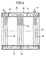
- the present invention is applied to a down-flowing type heat exhanger in which the refrigerant and cooling water flow in the vertical direction
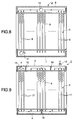
- the present invention is not limited to the above specific embodiment, but the present invention can also be applied to a cross-flowing type heat exchanger in which the refrigerant and cooling water flow in the lateral direction as shown in Figs. 4 and 5.
- the final flowing direction of the refrigerant in the core section conforms with the flowing direction of the cooling water of the radiator at least.
Abstract
Description
Claims (3)
- An integral type heat exchanger comprising:first and second radiator tanks opposed to each other;first and second condenser tanks opposed to each other, said first radiator tank being adjacent to said first condenser tank and said second radiator tank being adjacent to said second condenser tank; anda core section arranged between said first and second radiator tanks and between said first and second condenser tanks so as to be common between said radiator tanks and said condenser tanks,
wherein a cooling water flows from said first radiator tank into said second radiator tank through said core section at least in one direction, and a refrigerant flows between said first and second condenser tanks through said core section repeatedly, and
wherein a final flowing direction of the refrigerant in said core section conforms with a flowing direction of the cooling water. - The integral type heat exchanger according to claim 1, further comprising:a cooling water inflow pipe being open to said second radiator tank;a cooling water outflow pipe being open to said first radiator tank; anda refrigerant outflow pipe being open to said first condenser tank.
- The integral type heat exchanger according to claim 1, further comprising a refrigerant inflow pipe being open to said first condenser tank.
Applications Claiming Priority (3)
| Application Number | Priority Date | Filing Date | Title |
|---|---|---|---|
| JP2399897 | 1997-02-06 | ||
| JP2399897 | 1997-02-06 | ||
| JP23998/97 | 1997-02-06 |
Publications (2)
| Publication Number | Publication Date |
|---|---|
| EP0857935A2 true EP0857935A2 (en) | 1998-08-12 |
| EP0857935A3 EP0857935A3 (en) | 1999-06-16 |
Family
ID=12126257
Family Applications (1)
| Application Number | Title | Priority Date | Filing Date |
|---|---|---|---|
| EP98101850A Ceased EP0857935A3 (en) | 1997-02-06 | 1998-02-03 | Integral type heat exchanger |
Country Status (4)
| Country | Link |
|---|---|
| US (1) | US6230793B1 (en) |
| EP (1) | EP0857935A3 (en) |
| KR (1) | KR19980071122A (en) |
| AU (1) | AU5292898A (en) |
Cited By (2)
| Publication number | Priority date | Publication date | Assignee | Title |
|---|---|---|---|---|
| EP0869325A3 (en) * | 1997-03-31 | 1999-06-09 | Zexel Corporation | In-line integrated heat exchanger |
| EP1447635A1 (en) * | 2003-02-14 | 2004-08-18 | Calsonic Kansei Corporation | Heat exchanger for vehicle |
Families Citing this family (9)
| Publication number | Priority date | Publication date | Assignee | Title |
|---|---|---|---|---|
| DE19825561A1 (en) * | 1998-06-08 | 1999-12-09 | Valeo Klimatech Gmbh & Co Kg | Heat exchangers with ribbed flat tubes, in particular heating heat exchangers, engine coolers, condensers or evaporators, for motor vehicles |
| FR2796337B1 (en) * | 1999-07-12 | 2005-08-19 | Valeo Climatisation | HEATING-AIR CONDITIONING INSTALLATION FOR MOTOR VEHICLE |
| JP2001124486A (en) * | 1999-10-25 | 2001-05-11 | Denso Corp | Heat exchanger |
| LU90827B1 (en) * | 2001-09-07 | 2003-03-10 | Delphi Tech Inc | Assembly of a component of a vehicle air conditioning system to a support structure |
| KR100590658B1 (en) * | 2004-04-28 | 2006-06-19 | 모딘코리아 유한회사 | Header Pipe of Evaporator for Automobile |
| JP4970022B2 (en) * | 2006-08-02 | 2012-07-04 | カルソニックカンセイ株式会社 | Combined heat exchanger and combined heat exchanger system |
| US20100200195A1 (en) * | 2007-04-12 | 2010-08-12 | Automotivethermotech Gmbh | High-performance heat exchanger for automotive vehicles, and heating/air-conditioning device including a high-performance heat exchanger |
| US10767937B2 (en) | 2011-10-19 | 2020-09-08 | Carrier Corporation | Flattened tube finned heat exchanger and fabrication method |
| US11951797B2 (en) * | 2021-06-03 | 2024-04-09 | Brose Fahrzeugteile SE & Co. Kommanditgesellschaft, Würzburg | Cooling pack assembly |
Family Cites Families (22)
| Publication number | Priority date | Publication date | Assignee | Title |
|---|---|---|---|---|
| US4274481A (en) * | 1979-10-22 | 1981-06-23 | Stewart-Warner Corporation | Dry cooling tower with water augmentation |
| JPS5775115U (en) * | 1980-10-28 | 1982-05-10 | ||
| JPS58126215A (en) * | 1982-01-19 | 1983-07-27 | Nippon Denso Co Ltd | Heat exchanger |
| JPS61202084A (en) * | 1985-03-01 | 1986-09-06 | Showa Alum Corp | Heat exchanger |
| JPS6391488A (en) * | 1986-10-01 | 1988-04-22 | Showa Alum Corp | Heat exchanger |
| JP2756255B2 (en) | 1988-03-28 | 1998-05-25 | カルソニック株式会社 | Integrated heat exchanger |
| JPH0214578U (en) * | 1988-07-08 | 1990-01-30 | ||
| JPH0262270A (en) * | 1988-08-30 | 1990-03-02 | Canon Inc | Printing type recording apparatus |
| JPH0645155Y2 (en) | 1988-10-24 | 1994-11-16 | サンデン株式会社 | Heat exchanger |
| US5529116A (en) * | 1989-08-23 | 1996-06-25 | Showa Aluminum Corporation | Duplex heat exchanger |
| JP2786702B2 (en) * | 1989-12-07 | 1998-08-13 | 昭和アルミニウム株式会社 | Double integrated heat exchanger |
| US5080167A (en) * | 1990-06-12 | 1992-01-14 | General Motors Corporation | Combination radiator and condenser apparatus for motor vehicle |
| US5036910A (en) | 1990-06-12 | 1991-08-06 | General Motors Corporation | Combination radiator and condenser apparatus for motor vehicle |
| US5163507A (en) * | 1992-04-06 | 1992-11-17 | General Motors Corporation | Tank partition design for integral radiator/condenser |
| US5186246A (en) * | 1992-06-01 | 1993-02-16 | General Motors Corporation | Extruded coolant/refrigerant tank with separate headers |
| US5186243A (en) * | 1992-07-13 | 1993-02-16 | General Motors Corporation | Combination condenser and radiator tank thermal gap |
| ES2127472T3 (en) | 1994-04-12 | 1999-04-16 | Showa Aluminum Corp | STACKED DUPLEX HEAT EXCHANGER. |
| JP3371627B2 (en) * | 1995-07-20 | 2003-01-27 | 株式会社デンソー | Heat exchange equipment for vehicles |
| KR200152493Y1 (en) * | 1995-09-26 | 1999-07-15 | 류정열 | Sealing struture of condenser |
| US5671803A (en) * | 1995-10-23 | 1997-09-30 | General Motors Corporation | Modular condenser and fan shroud assembly |
| DE19602186C1 (en) * | 1996-01-23 | 1997-05-22 | Porsche Ag | Front end vehicle cooling system |
| KR19980055280U (en) * | 1996-12-26 | 1998-10-07 | 김욱한 | Radiator Condenser Integrated Heat Exchanger |
-
1998
- 1998-02-03 US US09/018,051 patent/US6230793B1/en not_active Expired - Fee Related
- 1998-02-03 EP EP98101850A patent/EP0857935A3/en not_active Ceased
- 1998-02-04 AU AU52928/98A patent/AU5292898A/en not_active Abandoned
- 1998-02-06 KR KR1019980003368A patent/KR19980071122A/en not_active Application Discontinuation
Non-Patent Citations (1)
| Title |
|---|
| None |
Cited By (3)
| Publication number | Priority date | Publication date | Assignee | Title |
|---|---|---|---|---|
| EP0869325A3 (en) * | 1997-03-31 | 1999-06-09 | Zexel Corporation | In-line integrated heat exchanger |
| EP1447635A1 (en) * | 2003-02-14 | 2004-08-18 | Calsonic Kansei Corporation | Heat exchanger for vehicle |
| US7328739B2 (en) | 2003-02-14 | 2008-02-12 | Calsonic Kansei Corporation | Heat exchanger for vehicle |
Also Published As
| Publication number | Publication date |
|---|---|
| KR19980071122A (en) | 1998-10-26 |
| AU5292898A (en) | 1998-08-13 |
| US6230793B1 (en) | 2001-05-15 |
| EP0857935A3 (en) | 1999-06-16 |
Similar Documents
| Publication | Publication Date | Title |
|---|---|---|
| EP0855566B1 (en) | Integrated heat exchanger | |
| US5341870A (en) | Evaporator or evaporator/condenser | |
| US7303003B2 (en) | Heat exchanger | |
| EP0857935A2 (en) | Integral type heat exchanger | |
| US5176200A (en) | Method of generating heat exchange | |
| US7013952B2 (en) | Stack type heat exchanger | |
| US7918266B2 (en) | Heat exchanger | |
| US20060144051A1 (en) | Evaporator designs for achieving high cooling performance at high superheats | |
| JP2007078292A (en) | Heat exchanger, and dual type heat exchanger | |
| JP4426189B2 (en) | Heat exchanger | |
| JP4328425B2 (en) | Stacked heat exchanger | |
| JPH0694329A (en) | Condenser for vehicle | |
| JPH05215482A (en) | Heat exchanger | |
| JPH10213391A (en) | Integral heat exchanger | |
| JP3677898B2 (en) | Double heat exchanger | |
| JPH1123185A (en) | Double tube type heat exchanger | |
| JPS6334489A (en) | Heat exchanger | |
| JP2002081797A (en) | Condenser | |
| JPH04340094A (en) | Heat exchanger | |
| JP4058824B2 (en) | Double heat exchanger | |
| JPH11337292A (en) | Heat exchanger | |
| JPH02130394A (en) | Heat exchanger | |
| KR100393564B1 (en) | Condenser for air-conditioner | |
| KR0129787Y1 (en) | Heat exchanger | |
| JPH07139852A (en) | Cap of heat exchanger pipe |
Legal Events
| Date | Code | Title | Description |
|---|---|---|---|
| PUAI | Public reference made under article 153(3) epc to a published international application that has entered the european phase |
Free format text: ORIGINAL CODE: 0009012 |
|
| AK | Designated contracting states |
Kind code of ref document: A2 Designated state(s): DE FR GB |
|
| AX | Request for extension of the european patent |
Free format text: AL;LT;LV;MK;RO;SI |
|
| PUAL | Search report despatched |
Free format text: ORIGINAL CODE: 0009013 |
|
| AK | Designated contracting states |
Kind code of ref document: A3 Designated state(s): AT BE CH DE DK ES FI FR GB GR IE IT LI LU MC NL PT SE |
|
| AX | Request for extension of the european patent |
Free format text: AL;LT;LV;MK;RO;SI |
|
| 17P | Request for examination filed |
Effective date: 19990914 |
|
| AKX | Designation fees paid |
Free format text: DE FR GB |
|
| RAP1 | Party data changed (applicant data changed or rights of an application transferred) |
Owner name: CALSONIC KANSEI CORPORATION |
|
| 17Q | First examination report despatched |
Effective date: 20010510 |
|
| STAA | Information on the status of an ep patent application or granted ep patent |
Free format text: STATUS: THE APPLICATION HAS BEEN REFUSED |
|
| 18R | Application refused |
Effective date: 20030320 |