EP0855258B1 - Rotational moulding plant - Google Patents
Rotational moulding plant Download PDFInfo
- Publication number
- EP0855258B1 EP0855258B1 EP98101444A EP98101444A EP0855258B1 EP 0855258 B1 EP0855258 B1 EP 0855258B1 EP 98101444 A EP98101444 A EP 98101444A EP 98101444 A EP98101444 A EP 98101444A EP 0855258 B1 EP0855258 B1 EP 0855258B1
- Authority
- EP
- European Patent Office
- Prior art keywords
- mold carrier
- sintering furnace
- carrier
- rotational moulding
- sintering oven
- Prior art date
- Legal status (The legal status is an assumption and is not a legal conclusion. Google has not performed a legal analysis and makes no representation as to the accuracy of the status listed.)
- Expired - Lifetime
Links
Images


Classifications
-
- B—PERFORMING OPERATIONS; TRANSPORTING
- B29—WORKING OF PLASTICS; WORKING OF SUBSTANCES IN A PLASTIC STATE IN GENERAL
- B29C—SHAPING OR JOINING OF PLASTICS; SHAPING OF MATERIAL IN A PLASTIC STATE, NOT OTHERWISE PROVIDED FOR; AFTER-TREATMENT OF THE SHAPED PRODUCTS, e.g. REPAIRING
- B29C41/00—Shaping by coating a mould, core or other substrate, i.e. by depositing material and stripping-off the shaped article; Apparatus therefor
- B29C41/02—Shaping by coating a mould, core or other substrate, i.e. by depositing material and stripping-off the shaped article; Apparatus therefor for making articles of definite length, i.e. discrete articles
- B29C41/04—Rotational or centrifugal casting, i.e. coating the inside of a mould by rotating the mould
- B29C41/06—Rotational or centrifugal casting, i.e. coating the inside of a mould by rotating the mould about two or more axes
-
- B—PERFORMING OPERATIONS; TRANSPORTING
- B29—WORKING OF PLASTICS; WORKING OF SUBSTANCES IN A PLASTIC STATE IN GENERAL
- B29C—SHAPING OR JOINING OF PLASTICS; SHAPING OF MATERIAL IN A PLASTIC STATE, NOT OTHERWISE PROVIDED FOR; AFTER-TREATMENT OF THE SHAPED PRODUCTS, e.g. REPAIRING
- B29C33/00—Moulds or cores; Details thereof or accessories therefor
- B29C33/34—Moulds or cores; Details thereof or accessories therefor movable, e.g. to or from the moulding station
-
- B—PERFORMING OPERATIONS; TRANSPORTING
- B29—WORKING OF PLASTICS; WORKING OF SUBSTANCES IN A PLASTIC STATE IN GENERAL
- B29C—SHAPING OR JOINING OF PLASTICS; SHAPING OF MATERIAL IN A PLASTIC STATE, NOT OTHERWISE PROVIDED FOR; AFTER-TREATMENT OF THE SHAPED PRODUCTS, e.g. REPAIRING
- B29C41/00—Shaping by coating a mould, core or other substrate, i.e. by depositing material and stripping-off the shaped article; Apparatus therefor
- B29C41/34—Component parts, details or accessories; Auxiliary operations
- B29C41/46—Heating or cooling
-
- Y—GENERAL TAGGING OF NEW TECHNOLOGICAL DEVELOPMENTS; GENERAL TAGGING OF CROSS-SECTIONAL TECHNOLOGIES SPANNING OVER SEVERAL SECTIONS OF THE IPC; TECHNICAL SUBJECTS COVERED BY FORMER USPC CROSS-REFERENCE ART COLLECTIONS [XRACs] AND DIGESTS
- Y10—TECHNICAL SUBJECTS COVERED BY FORMER USPC
- Y10S—TECHNICAL SUBJECTS COVERED BY FORMER USPC CROSS-REFERENCE ART COLLECTIONS [XRACs] AND DIGESTS
- Y10S425/00—Plastic article or earthenware shaping or treating: apparatus
- Y10S425/20—Molding plants
- Y10S425/201—Diverse stations
Definitions
- the present invention relates to a rotary molding machine with a sintering furnace, at least one cooling chamber and at least a means of transport for receiving at least one Shaped body and for transporting the mold carrier between the sintering furnace and the at least one cooling chamber.
- Such systems are used for the production of hollow plastic bodies in hollow molds that are held by the mold carrier.
- the hollow molds filled with plastic powder or sinter powder and in the sintering furnace heated by performing a rotational movement.
- the mold carrier is made hollow by the means of transport Cooling chamber spent where continuing a rotational movement the mold is cooled.
- a generic rotary molding machine is from GB-A-1 334 331 known.
- the system described has a circular shape rotating transport means arranged cooling chambers and one Sintering furnace.
- the one that works like a carousel Transport means has four arms for receiving mold carriers on by a rotational movement of the means of transport between the individual stages of the manufacturing process be moved.
- the sintering furnace can be moved in the radial direction, around one of the mold carriers attached to the arms enclose.
- the sintering furnace surrounds during the melting process the mold carrier only from five sides; a flap of the Sintering furnace must be caused by the rigid arm of the means of transport remain open, resulting in high Energy losses result during the melting process.
- a rotary molding machine is known from EP 01 77 906 A2, in which a number of cooling chambers are circular around a sintering furnace is arranged and on as a means of transport Rails movable between the cooling chambers and the sintering furnace Tool carrier serves.
- the system has the disadvantage that they are due to the circular arrangement of the cooling chambers around the sintering furnace is very space consuming and that the heating chamber must either be dimensioned so large that the mold carrier including means of transport can be included or that here too the sintering furnace with some remaining outside Means of transport cannot be closed completely.
- Another generic device is made of: wildfire, E .: "Rotation forms - process engineering overview", plastics und Kautschuk, 21. vol., Issue 3, 1974, pp. 203 to 207.
- a rotary system there in series described a heating chamber arranged cooling chambers, wherein serve as a means of transport tool carrier on a Rail can be moved next to the cooling chambers and the heating chamber and which telescopic arms for inserting a rotary molding tool into the cooling chambers or the heating chamber exhibit.
- the heating chamber is completely closed not due to the telescopic arm of the means of transport possible.
- so many means of transport are always required how mold carriers are in the manufacturing process.
- the aim of the present invention is therefore a rotary molding system to make available to realize the space-saving is and the optimal use of the supplied Energy works. Furthermore, those for the known Rotation molding machines described disadvantages can be avoided.
- This goal is achieved by means of a rotary molding system described at the beginning solved, in which the sintering furnace and at least a cooling chamber first rotating devices for receiving the mold carrier exhibit.
- the mold carrier can be completely in the sintering furnace or Cooling chambers introduced and the sintering furnace or the cooling chambers can completely during the melting or cooling process getting closed.
- the latter aspect creates an optimal one Utilization of the energy used for heating or cooling.
- the means of transport used for transport of the mold carrier between the cooling chambers and the sintering furnace is used to transport other form carriers, while a mold carrier is in the sintering furnace or in the Cooling chamber is located. This helps reduce overall costs the rotary molding machine.
- the sintering furnace and two cooling chambers are advantageous and a demolding station arranged in series. This results in a particularly space-saving implementation the rotary molding system according to the invention.
- the space requirement can be according to another embodiment be further reduced in that the means of transport as Mold carrier carriage is formed, which is below the sintering furnace and the at least one cooling chamber is movable. From this results in a rotary molding machine with a minimal footprint, those available to the top in modern manufacturing facilities uses standing space.
- the mold carrier carriage has one Lifting device up to the mold carrier from below into the sintering furnace or to introduce the cooling chambers. Since the sintering furnace for Insertion of the mold carrier to be opened from below escapes less heat than when opening on one of the other sides would be the case. This proves to be another advantage this embodiment.
- the system described offers the Possibility of using different shapes in the same system Process duration to deal with, since a mold carrier is in the process flow can overtake the other. This is an optimal utilization the system guaranteed.
- the sintering furnace is rotatably supported by means of a second rotating device, a second predetermined by the second rotating device Axis of rotation and a through the first receiving the mold carrier Rotation device predetermined first axis of rotation is not parallel run.
- the mold carrier thus executes through its own rotation and the rotation of the sintering furnace in the sintering furnace is a rotational movement, an optimal distribution of the melted Powder inside the one held by the mold carrier Cavity causes.
- the first rotating devices have to accommodate the mold carrier the sintering furnace or the cooling chambers, who attack on opposite sides of the mold carrier and which extend the first axes of rotation, especially pneumatically, are movable to clamp the form carrier or to release. At least one of the two clamping elements is driven by an electric motor to rotate the mold carrier. For establishing a torque-resistant connection that has between this clamping element and the mold carrier Clamping element on the front approaches and / or recesses that on corresponding recesses and / or approaches of the mold carrier attack for torque transmission.
- the mold carrier carriage also has a rotating device to the mold carrier during transportation from the sintering furnace to keep the cooling chambers rotating.
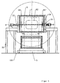
- Figures 1 and 2 is a rotary molding system according to the invention in side view ( Figure 1) and top view ( Figure 2) shown.
- the rotary molding plant has a sintering furnace 1 and two cooling chambers 8, 9 arranged in series therewith.
- a demolding station 12 which is used for Provision of new mold carriers and for demoulding the mold carriers or the hollow molds after the cooling process has been completed serves.
- a control cabinet 80 is provided for the sake of completeness shown that the required to control the system Electronics.
- the sintering furnace 1, the cooling chambers 8, 9 and the demolding station 12 have first rotating devices 3, 10, 11, 13 for rotating Inclusion of a mold carrier 6, which is used to manufacture necessary hollow molds of plastic objects.
- the structure and operation of the identical first turning devices 3, 10, 11, 13 takes place in detail using the first Rotary device of the sintering furnace 1 in FIGS. 4 and 5.
- the sintering furnace 1 and the cooling chambers 8, 9 are on supports 30, 86, 96 stored, whereby a mold carrier 5, which is used for transport of the mold carrier 6 between the demolding station 12, the Sintering furnace 1 and the cooling chambers 8, 9 serves on a rail 100 can be moved below the sintering furnace and the cooling chambers 8, 9 is.
- the mold carrier carriage 5 points to the rail 100 attacking wheels 58 and one in Figures 1 and 2 not closer shown lifting device, by means of which the mold carrier 6 from below into the sintering furnace 1 or the cooling chambers 8, 9 introduced and after completion of the sintering or cooling process is removable again.
- the dash-dotted circles in Figure 1 and the dash-dotted rectangles in Figure 2 indicate the position of a mold carrier having maximum dimensions below or within the sintering furnace 1 and Cooling chambers 8, 9 and in the demolding station 12.
- Blowers 82, 92 are arranged on the cooling chambers 8, 9 Suck air, which via air outlet nozzles 84, 94 into the interior the cooling chambers 8, 9 are blown in to cool a mold carrier becomes.
- Figures 3 to 5 show a more detailed representation of the Sintering furnace 1 and the device supporting it in two Side views and in plan view, with one in FIG Mold carrier 6 on the mold carrier carriage 5 outside the sintering furnace 1 and in Figures 4 and 5 within the sintering furnace 1 is located.
- the mold carrier 6 consists in the examples shown a rectangular frame in which by means of struts 66 a hollow mold 62 is held. On two opposite ones A circular disk 64, 64 'is attached to each side, for the rotatable mounting of the mold carrier 6 on four rollers 56, 56 ', 58 of the mold carrier carriage 5 is used.
- Figure 6 shows one lateral representation of the placed on the mold carrier 5 Mold carrier 6.
- the mold carrier 5 has a rotating device to carry out a rotational movement of the mold carrier 6 on the rollers 56, 56 ', 58.
- the rotating device of the Mold carrier carriage 5 has a drive motor 59, which a chain 53 one of the rollers 56 'on which the mold carrier 6 by means of the disks 64, 64 ', drives.
- the mold carrier 5 also has a lifting device 52, by means of which the mold carrier 6 from below be introduced into the sintering furnace 1 and removed can.
- An opening of the sintering furnace 1 for taking in or taking out the mold carrier 6 is by means of an electric motor actuatable flap 2, 2 'closable, which in Figure 3 in closed Position (2) and open position (2 ') shown is.
- the sintering furnace 1 has a rotating device 3 for receiving of the mold carrier 6, with this rotating device 3 corresponding Rotating devices 10, 11, 13 in the in the figures 1 and 2 shown cooling chambers 8, 9 and the demolding station 12 are available.
- the rotating device 3 has in particular pneumatically displaceable along a first axis of rotation B-B ' first and second clamping elements 32, 34 for receiving the mold carrier 6.
- the second clamping element 34 has an end face disc-like element 36 with lugs, these lugs in corresponding recesses 65 'of the disk 64' of Intervene mold carrier 6 to produce a torque lock.
- On the representation of the sprocket explained in Figure 6 51 is in the figures for the sake of clarity 4 and 5 waived.
- the sprocket 51 has a recess , whereby the disc-like element 36 on the disc 64 ' can attack.
- the second clamping element 34 is an electric motor driven to the mold carrier 6 after torque with the second clamping element 34 into a rotational movement to move the axis of rotation B-B '.
- the first clamping element 32 engages in a recess 65 of the circular face Washer 64 of the mold carrier 6 to be together with the second Clamping element 34 to hold the mold carrier 6.
- the mold carrier 6 is by means of the mold carrier 5 under the sintering furnace 1 already opened. By means of the lifting device 52, the mold carrier 6 is raised until it is on is at a height at which the clamping elements 32, 34 on the engage corresponding recesses 65, 65 'of the mold carrier 6 can.
- the clamping elements 32, 34 are now pneumatically in pressed axially against the mold carrier 6, which first clamping element 32 in the corresponding recess 65 of the Mold carrier 6 engages.
- a rotation of the second follows Clamping element 34 to the approaches of the end plate 36 in the Engage recesses 65 'of the mold carrier 6.
- the mold carrier 6 is held by the two clamping elements 32, 34 which Lifting device 52 is then lowered and the flap 2 is closed.
- the flap will open 2 opened, the lifting device 52 extended until the two disks 64, 64 'of the mold carrier 6 on the rollers 56, 56 ', 58 of the holding device 54 of the mold carrier carriage 5 rest.
- the clamping elements 32, 34 are when the molded body is rotating 6 withdrawn to release the mold carrier 6.
- the Rotational movement of the mold carrier 6 is now by the electromotive Rotating device of the mold carrier carriage 5 causes whose lifting device 52 is for removing the mold carrier 6 lowers and the mold carrier 6 with rotation to one of the Cooling chambers 8, 9 conveyed.
- the mold carrier is during the melting or cooling processes 5 freely movable over the entire length of the rotary molding system and can approach each of the stations of the rotary molding system. While both cooling chambers 8, 9 are still equipped, can for example already from the demolding station 12 new mold carrier are brought and brought into the sintering furnace 1.
- the mold carrier 6 is also in the demolding station 12 by means of a pneumatically operated clamping device to the electric motor driven first rotating device 13 coupled and from the latter into one suitable for the removal of the end products Position rotated. Then the shapes are again with Material filled and by means of the mold carrier 5 to the sintering furnace 1 driven.
- the mode of operation of the sintering furnace 1 is in particular Figure 3 can be seen.
- the sintering furnace 1 is arranged on supports 30 and via an electric motor-driven shaft 39 mounted rotatably about a second axis of rotation A-A '.
- the wave 39 is mounted by means of bearings 37, 38.
- a burner with a burner tube 15 for heating the Inside the furnace with a gas flame Located inside the sintering furnace 1 a burner with a burner tube 15 for heating the Inside the furnace with a gas flame.
- An air duct 16 with Air outlet nozzles 14 ensure the air circulation within of the sintering furnace.
- the gas and air supply takes place through the Feed lines 17, 18 shown in dashed lines in FIG. 3 within the shaft 39 supporting the sintering furnace 1.
- a total of three mold carriers 6 are preferably available.
- the mold carrier carriage 5 with its lifting device 52 is like this controlled that an optimal production flow and a smooth Transport of the mold carriers between the sintering furnace 1, the cooling chamber 8 and 9 and the demolding station 12 guaranteed is.
Landscapes
- Engineering & Computer Science (AREA)
- Mechanical Engineering (AREA)
- Powder Metallurgy (AREA)
- Moulding By Coating Moulds (AREA)
- Tunnel Furnaces (AREA)
- Water Treatment By Electricity Or Magnetism (AREA)
- Furnace Charging Or Discharging (AREA)
Abstract
Description
Die vorliegende Erfindung betrifft eine Rotationsformanlage mit einem Sinterofen, wenigstens einer Kühlkammer und wenigstens einem Transportmittel zur Aufnahme wenigstens eines Formkörpers und zum Transport des Formträger zwischen dem Sinterofen und der wenigstens einen Kühlkammer.The present invention relates to a rotary molding machine with a sintering furnace, at least one cooling chamber and at least a means of transport for receiving at least one Shaped body and for transporting the mold carrier between the sintering furnace and the at least one cooling chamber.
Derartige Anlagen dienen zur Herstellung von Kunststoffhohlkörpern in Hohlformen, die durch den Formträger gehalten werden. Während des Herstellungsprozesses werden die Hohlformen mit Kunststoffpulver oder Sinterpulver gefüllt und im Sinterofen unter Durchführung einer Rotationsbewegung erwärmt. Nach Aufschmelzen und gleichmäßiger Verteilung des Pulvers in der Hohlform wird der Formträger durch das Transportmittel zu der Kühlkammer verbracht, wo unter Fortführung einer Rotationsbewegung die Hohlform abgekühlt wird.Such systems are used for the production of hollow plastic bodies in hollow molds that are held by the mold carrier. During the manufacturing process, the hollow molds filled with plastic powder or sinter powder and in the sintering furnace heated by performing a rotational movement. To Melting and even distribution of the powder in the The mold carrier is made hollow by the means of transport Cooling chamber spent where continuing a rotational movement the mold is cooled.
Eine gattungsgemäße Rotationsformanlage ist aus der GB-A-1 334 331 bekannt. Die beschriebene Anlage weist kreisförmig um ein rotierendes Transportmittel angeordnete Kühlkammern und einen Sinterofen auf. Das nach Art eines Karussells arbeitende Transportmittel weist vier Arme zur Aufnahme von Formträgern auf, die durch eine Rotationsbewegung des Transportmittels zwischen den einzelnen Stationen des Herstellungsprozesses bewegt werden. Der Sinterofen ist in radialer Richtung verfahrbar, um einen der an den Armen befestigten Formträger zu umschließen. Während des Schmelzprozesses umgibt der Sinterofen den Formträger lediglich von fünf Seiten; eine Klappe des Sinterofens muß während des Schmelzprozesses bedingt durch den starren Arm des Transportmittels offen bleiben, woraus hohe Energieverluste während des Schmelzprozesses resultieren.A generic rotary molding machine is from GB-A-1 334 331 known. The system described has a circular shape rotating transport means arranged cooling chambers and one Sintering furnace. The one that works like a carousel Transport means has four arms for receiving mold carriers on by a rotational movement of the means of transport between the individual stages of the manufacturing process be moved. The sintering furnace can be moved in the radial direction, around one of the mold carriers attached to the arms enclose. The sintering furnace surrounds during the melting process the mold carrier only from five sides; a flap of the Sintering furnace must be caused by the rigid arm of the means of transport remain open, resulting in high Energy losses result during the melting process.
Aus der EP 01 77 906 A2 ist eine Rotationsformanlage bekannt, bei welcher eine Anzahl Kühlkammern kreisförmig um einen Sinterofen angeordnet ist und bei der als Transportmittel ein auf Schienen zwischen den Kühlkammern und dem Sinterofen verfahrbarer Werkzeugträger dient. Die Anlage besitzt den Nachteil, daß sie aufgrund der kreisförmigen Anordnung der Kühlkammern um den Sinterofen sehr platzaufwendig ist und daß die Heizkammer entweder so groß dimensioniert sein muß, daß der Formträger samt Transportmittel aufgenommen werden kann oder daß auch hier der Sinterofen bei teilweise außerhalb verbleibendem Transportmittel nicht vollständig geschlossen werden kann.A rotary molding machine is known from EP 01 77 906 A2, in which a number of cooling chambers are circular around a sintering furnace is arranged and on as a means of transport Rails movable between the cooling chambers and the sintering furnace Tool carrier serves. The system has the disadvantage that they are due to the circular arrangement of the cooling chambers around the sintering furnace is very space consuming and that the heating chamber must either be dimensioned so large that the mold carrier including means of transport can be included or that here too the sintering furnace with some remaining outside Means of transport cannot be closed completely.
Eine weitere gattungsgemäße Vorrichtung ist aus: Wildfeuer,
E.: "Rotationsformen - Verfahrenstechnische Übersicht", Plaste
und Kautschuk, 21. Jg., Heft 3, 1974, S. 203 bis 207, bekannt.
Dort ist insbesondere eine Rotationsanlage mit in Reihe zu
einer Heizkammer angeordneten Kühlkammern beschrieben, wobei
als Transportmittel Werkzeugträger dienen, die auf einer
Schiene neben den Kühlkammern und der Heizkammer verfahrbar
sind und welche teleskopartige Arme zum Einbringen eines Rotationsformwerkzeuges
in die Kühlkammern bzw. die Heizkammer
aufweisen. Auch hier ist ein vollständiges Schließen der Heizkammer
bedingt durch den Teleskoparm der Transportmittel nicht
möglich. Ferner sind stets so viele Transportmittel erforderlich,
wie sich gerade Formträger im Fertigungsprozess befinden.Another generic device is made of: wildfire,
E .: "Rotation forms - process engineering overview", plastics
und Kautschuk, 21. vol.,
Weitere gattungsgemäße Vorrichtungen sind in der US 4,102,624, der US 4,632,654 und der US 3,907,482 bekannt.Further generic devices are known in US 4,102,624, US 4,632,654 and US 3,907,482.
Ziel der vorliegenden Erfindung ist es daher, eine Rotationsformanlage zur Verfügung zu stellen, die platzsparend zu realisieren ist und die unter optimaler Ausnutzung der zugeführten Energie arbeitet. Ferner sollen die für die bekannten Rotationsformanlagen beschriebenen Nachteile vermieden werden.The aim of the present invention is therefore a rotary molding system to make available to realize the space-saving is and the optimal use of the supplied Energy works. Furthermore, those for the known Rotation molding machines described disadvantages can be avoided.
Dieses Ziel wird durch eine eingangs beschriebene Rotationsformanlage gelöst, bei der der Sinterofen und die wenigstens eine Kühlkammer erste Drehvorrichtungen zur Aufnahme des Formträgers aufweisen.This goal is achieved by means of a rotary molding system described at the beginning solved, in which the sintering furnace and at least a cooling chamber first rotating devices for receiving the mold carrier exhibit.
Der Formträger kann so vollständig in den Sinterofen bzw. die Kühlkammern eingebracht und der Sinterofen bzw. die Kühlkammern können während des Schmelz- bzw. Kühlvorgangs vollständig geschlossen werden. Letzterer Aspekt bewirkt eine optimale Ausnutzung der zur Erhitzung bzw. Kühlung aufgewandten Energie. Ferner kann das Transportmittel, welches zum Transport des Formträgers zwischen den Kühlkammern und dem Sinterofen dient, zur Beförderung weiterer Formtäger verwendet werden, während sich ein Formträger gerade im Sinterofen oder in der Kühlkammer befindet. Dies trägt zur Reduzierung der Gesamtkosten der Rotationsformanlage bei.The mold carrier can be completely in the sintering furnace or Cooling chambers introduced and the sintering furnace or the cooling chambers can completely during the melting or cooling process getting closed. The latter aspect creates an optimal one Utilization of the energy used for heating or cooling. Furthermore, the means of transport used for transport of the mold carrier between the cooling chambers and the sintering furnace is used to transport other form carriers, while a mold carrier is in the sintering furnace or in the Cooling chamber is located. This helps reduce overall costs the rotary molding machine.
Vorteilhafte Ausgestaltungen der Erfindung sind Gegenstand der Unteransprüche.Advantageous embodiments of the invention are the subject of Dependent claims.
Vorteilhafterweise sind der Sinterofen und zwei Kühlkammern sowie eine Entformstation hintereinander in Reihe angeordnet. Hierdurch ergibt sich eine besonders platzsparende Realisierung der erfindungsgemäßen Rotationsformanlage.The sintering furnace and two cooling chambers are advantageous and a demolding station arranged in series. This results in a particularly space-saving implementation the rotary molding system according to the invention.
Der Platzbedarf kann gemäß einer weiteren Ausführungsform weiter dadurch reduziert werden, daß das Transportmittel als Formträgerwagen ausgebildet ist, der unterhalb des Sinterofens und der wenigstens einen Kühlkammer verfahrbar ist. Hieraus resultiert eine Rotationsformanlage mit minimaler Standfläche, die den in modernen Fabrikationsstätten nach oben zur Verfügung stehenden Raum nutzt. Der Formträgerwagen weist eine Hubeinrichtung auf, um die Formträger von unten in den Sinterofen bzw. die Kühlkammern einzubringen. Da der Sinterofen zum Einbringen des Formträgers von unten zu öffnen ist, entweicht weniger Wärme, als dies bei Öffnung an einer der anderen Seiten der Fall wäre. Dies erweist sich als ein weiterer Vorteil dieser Ausführungsform. Die beschriebene Anlage bietet die Möglichkeit, in derselben Anlage Formen mit unterschiedlicher Prozeßdauer zu behandeln, da im Prozeßablauf ein Formträger den anderen überholen kann. Hierdurch ist eine optimale Auslastung der Anlage gewährleistet.The space requirement can be according to another embodiment be further reduced in that the means of transport as Mold carrier carriage is formed, which is below the sintering furnace and the at least one cooling chamber is movable. From this results in a rotary molding machine with a minimal footprint, those available to the top in modern manufacturing facilities uses standing space. The mold carrier carriage has one Lifting device up to the mold carrier from below into the sintering furnace or to introduce the cooling chambers. Since the sintering furnace for Insertion of the mold carrier to be opened from below escapes less heat than when opening on one of the other sides would be the case. This proves to be another advantage this embodiment. The system described offers the Possibility of using different shapes in the same system Process duration to deal with, since a mold carrier is in the process flow can overtake the other. This is an optimal utilization the system guaranteed.
Eine weitere Ausführungsform sieht vor, daß der Sinterofen mittels einer zweiten Drehvorrichtung drehbar gelagert ist, wobei eine durch die zweite Drehvorrichtung vorgegebene zweite Drehachse und eine durch die den Formträger aufnehmende erste Drehvorrichtung vorgegebene erste Drehachse nicht parallel verlaufen. Der Formträger vollzieht so durch seine Eigenrotation und die Rotation des Sinterofens im Sinterofen eine Rotationsbewegung, die eine optimale Verteilung des aufgeschmolzenen Pulvers im Inneren der durch den Formträger gehaltenen Hohlformen bewirkt.Another embodiment provides that the sintering furnace is rotatably supported by means of a second rotating device, a second predetermined by the second rotating device Axis of rotation and a through the first receiving the mold carrier Rotation device predetermined first axis of rotation is not parallel run. The mold carrier thus executes through its own rotation and the rotation of the sintering furnace in the sintering furnace is a rotational movement, an optimal distribution of the melted Powder inside the one held by the mold carrier Cavity causes.
Zur Aufnahme des Formträgers weisen die ersten Drehvorrichtungen des Sinterofens bzw. der Kühlkammern Spannelemente auf, die an gegenüberliegenden Seiten des Fromträgers angreifen und die in Verlängerung der ersten Drehachsen, insbesondere pneumatisch, verschiebbar sind, um den Fromträger einzuspannen bzw. freizugeben. Wenigstens eines der beiden Spannelemente wird elektromotorisch zur Rotation des Formträgers angetrieben. Zur Herstellung einer drehmomentsahlüssigen Verbindung zwischen diesem Spannelement und dem Formträger weist das Spannelement stirnseitig Ansätze und/oder Rücksprünge auf, die an entsprechenden Rücksprüngen und/oder Ansätzen des Formträgers zur Drehmomenübertragung angreifen.The first rotating devices have to accommodate the mold carrier the sintering furnace or the cooling chambers, who attack on opposite sides of the mold carrier and which extend the first axes of rotation, especially pneumatically, are movable to clamp the form carrier or to release. At least one of the two clamping elements is driven by an electric motor to rotate the mold carrier. For establishing a torque-resistant connection that has between this clamping element and the mold carrier Clamping element on the front approaches and / or recesses that on corresponding recesses and / or approaches of the mold carrier attack for torque transmission.
Weiterhin weist auch der Formträgerwagen eine Drehvorrichtung auf, um den Formträger während des Transportes von dem Sinterofen zu den Kühlkammern in Rotation zu halten.Furthermore, the mold carrier carriage also has a rotating device to the mold carrier during transportation from the sintering furnace to keep the cooling chambers rotating.
Die Erfindung wird nachfolgend anhand von Ausführungsbeispielen mittels Figuren näher erläutert. Es zeigen:
- Figur 1:
- Erfindungsgemäße Rotationsformanlage in Seitenansicht;
- Figur 2:
- Rotationsformanlage gemäß
Figur 1 in Draufsicht; Figuren 3, 4, 5:- Sinterofen der erfindungsgemäßen Rotationsformanlage in Seitenansicht und Draufsicht (Figur 4);
- Figur 6:
- Formträgerwagen mit Formträger in Seitenansicht.
- Figure 1:
- Rotary molding machine according to the invention in side view;
- Figure 2:
- Rotary molding machine according to Figure 1 in plan view;
- Figures 3, 4, 5:
- Sintering furnace of the rotary molding plant according to the invention in side view and top view (FIG. 4);
- Figure 6:
- Mold carrier carriage with mold carrier in side view.
In den Figuren bezeichnen, sofern nicht anders angegeben, gleiche Bezugszeichen gleiche Teile mit gleicher Bedeutung.In the figures, unless otherwise stated, same reference numerals same parts with the same meaning.
In den Figuren 1 und 2 ist eine erfindungsgemäße Rotationsformanlage
in Seitenansicht (Figur 1) und Draufsicht (Figur 2)
dargestellt. Die Rotationsformanlage weist einen Sinterofen 1
und zwei in Reihe zu diesem angeordnete Kühlkammern 8, 9 auf.
In Reihe dazu ist eine Entformstation 12 angeordnet, die zur
Bereitstellung neuer Formträger und zur Entformung der Formträger
bzw. der Hohlformen nach Abschluß des Kühlprozesses
dient. Der Vollständigkeit halber ist ein Schaltschrank 80
dargestellt, der die zur Steuerung der Anlage erforderliche
Elektronik aufnimmt.In Figures 1 and 2 is a rotary molding system according to the invention
in side view (Figure 1) and top view (Figure 2)
shown. The rotary molding plant has a
Der Sinterofen 1, die Kühlkammern 8, 9 und die Entformstation
12 besitzen erste Drehvorrichtungen 3, 10, 11, 13 zur drehbaren
Aufnahme eines Formträgers 6, der die zur Herstellung
von Kunststoffgegenständen erforderlichen Hohlformen trägt.
Der Aufbau und die Funktionsweise der identischen ersten Drehvorrichtungen
3, 10, 11, 13 erfolgt im Detail anhand der ersten
Drehvorrichtung des Sinterofens 1 in den Figuren 4 und 5.The
Der Sinterofen 1 und die Kühlkammern 8, 9 sind auf Stützen 30,
86, 96 gelagert, wodurch ein Formträgerwagen 5, der zum Transport
des Formträgers 6 zwischen der Entformstation 12, dem
Sinterofen 1 und den Kühlkammern 8, 9 dient, auf einer Schiene
100 unterhalb des Sinterofens und der Kühlkammern 8, 9 verfahrbar
ist. Der Formträgerwagen 5 weist an die Schiene 100
angreifende Räder 58 und eine in Figur 1 und 2 nicht näher
dargestellte Hubvorrichtung auf, mittels welcher der Formträger
6 von unten in den Sinterofen 1 bzw. die Kühlkammern 8,
9 eingebracht und nach Beendigung des Sinter- bzw. Kühlvorganges
wieder entnehmbar ist. Die strichpunktierten Kreise in
Figur 1 bzw. die strichpunktierten Rechtecke in Figur 2 deuten
die Position eines maximale Abmessungen aufweisenden Formträgers
unterhalb bzw. innerhalb des Sinterofens 1 und der
Kühlkammern 8, 9 sowie in der Entformstation 12 an.The
Auf den Kühlkammern 8, 9 sind Gebläse 82, 92 angeordnet, die
Luft ansaugen, welche über Luftauslaßdüsen 84, 94 ins Innere
der Kühlkammern 8, 9 zur Kühlung eines Formträgers eingeblasen
wird.
Die Figuren 3 bis 5 zeigen eine detailliertere Darstellung des
Sinterofens 1 und der diesen tragenden Vorrichtung in zwei
Seitenansichten und in Draufsicht, wobei sich in Figur 3 ein
Formträger 6 auf dem Formträgerwagen 5 außerhalb des Sinterofens
1 und in den Figuren 4 und 5 innerhalb des Sinterofens
1 befindet.Figures 3 to 5 show a more detailed representation of the
Der Formträger 6 besteht in den dargestellten Beispielen aus
einem rechteckförmigen Rahmen in dem mittels Verstrebungen 66
eine Hohlform 62 gehalten ist. An zwei sich gegenüberliegenden
Seiten ist je eine kreisförmige Scheibe 64, 64' angebracht,
die zur drehbaren Lagerung des Formträgers 6 auf vier Rollen
56, 56', 58 des Formträgerwagens 5 dient. Figur 6 zeigt eine
seitliche Darstellung des auf den Formträgerwagen 5 aufgesetzten
Formträgers 6. Der Formträgerwagen 5 besitzt eine Drehvorrichtung
zur Durchführung einer Rotationsbewegung des Formträgers
6 auf den Rollen 56, 56', 58. Die Drehvorrichtung des
Formträgerwagens 5 weist einen Antriebsmotor 59 auf, der über
eine Kette 53 eine der Rollen 56', auf denen der Formträger 6
mittels der Scheiben 64, 64' aufliegt, antreibt. Gleichzeitig
steht die Kette 53 in Eingriff mit einem Kettenrad 51, das als
Teil des Formträgers 6 benachbart zu der Scheibe 64 angeordnet
und mit letzterer fest verbunden ist, um den Formträger 6 in
Rotation zu versetzen. Der Formträgerwagen 5 besitzt ferner
eine Hubvorrichtung 52, mittels der der Formträger 6 von unten
in den Sinterofen 1 eingebracht und herausgenommen werden
kann.The
Eine Öffnung des Sinterofens 1 zum Hineinbringen oder Herausnehmen
des Formträgers 6 ist mittels einer elektromotorisch
betätigbaren Klappe 2, 2' verschließbar, die in Figur 3 in geschlossener
Position (2) und offener Position (2') dargestellt
ist.An opening of the
Der Sinterofen 1 weist eine Drehvorrichtung 3 zur Aufnahme
des Formträgers 6 auf, wobei dieser Drehvorrichtung 3 entsprechende
Drehvorrichtungen 10, 11, 13 in den in den Figuren
1 und 2 dargestellten Kühlkammern 8, 9 und der Entformstation
12 vorhanden sind. Die Drehvorrichtung 3 besitzt insbesondere
pneumatisch, entlang einer ersten Drehachse B-B' verschiebbare
erste und zweite Spannelemente 32, 34 zur Aufnahme des Formträgers
6. Das zweite Spannelement 34 weist stirnseitig ein
scheibenartiges Element 36 mit Ansätzen auf, wobei diese Ansätze
in entsprechende Aussparungen 65' der Scheibe 64' des
Formträgers 6 zur Herstellung eines Drehmomentschlusses eingreifen.
Auf die Darstellung des in Figur 6 erläuterten Kettenrades
51 ist aus Gründen der Übersichtlichkeit in den Figuren
4 und 5 verzichtet. Das Kettenrad 51 weist eine Ausnehmung
auf, wodurch das scheibenartige Element 36 an der Scheibe 64'
angreifen kann. Das zweite Spannelement 34 ist elektromotorisch
angetrieben, um den Formträger 6 nach Drehmomentschluß
mit dem zweiten Spannelement 34 in eine Rotationsbewegung um
die Drehachse B-B' zu versetzen. Das erste Spannelement 32
greift stirnseitig in eine Aussparung 65 der kreisförmigen
Scheibe 64 des Formträgers 6 ein, um zusammen mit dem zweiten
Spannelement 34 den Formträger 6 zu halten.The
Im folgenden soll kurz das Einbringen und Herausnehmen des
Formträgers 6 in den und aus dem Sinterofen 1 beschrieben
werden.In the following, the insertion and removal of the
Der Formträger 6 wird mittels des Formträgerwagens 5 unter den
bereits geöffneten Sinterofen 1 gebracht. Mittels der Hubvorrichtung
52 wird der Formträger 6 angehoben, bis er sich auf
einer Höhe befindet, auf der die Spannelemente 32, 34 an den
entsprechenden Ausnehmungen 65, 65' des Formträgers 6 angreifen
können. Die Spannelemente 32, 34 werden nun pneumatisch in
axialer Richtung gegen den Formträger 6 gedrückt, wobei das
erste Spannelement 32 in die entsprechende Aussparung 65 des
Formträgers 6 eingreift. Es folgt eine Rotation des zweiten
Spannelements 34 bis die Ansätze der Stirnscheibe 36 in die
Aussparungen 65' des Formträgers 6 eingreifen. Der Formträger
6 ist so durch die beiden Spannelemente 32, 34 gehalten, die
Hubvorrichtung 52 wird dann abgesenkt und die Klappe 2 geschlossen.
Nach Beendigung des Schmelzvorganges wird die Klappe
2 geöffnet, die Hubvorrichtung 52 ausgefahren, bis die
beiden Scheiben 64, 64' des Formträgers 6 auf den Rollen 56,
56', 58 der Haltevorrichtung 54 des Formträgerwagens 5 aufliegen.
Die Spannelemente 32, 34 werden bei rotierendem Formkörper
6 zurückgezogen, um den Formträger 6 freizugeben. Die
Rotationsbewegung des Formträgers 6 wird nun durch die elektromotorische
Drehvorrichtung des Formträgerwagens 5 bewirkt,
dessen Hubvorrichtung 52 sich zur Herausnahme des Formträgers
6 absenkt und der den Formträger 6 unter Rotation zu einer der
Kühlkammern 8, 9 befördert. Das Einbringen und Herausnehmen
des Formträgers 6 in die bzw. aus den Kühlkammern 8, 9 erfolgt
von unten entsprechend dem Einbringen in den Sinterofen 1,
wobei der Formträger 6 während des Kühlprozesses durch die
ersten Drehvorrichtungen 10, 11, die in Funktion und Aufbau
der ersten Drehvorrichtung 3 des Sinterofens 1 entprechen, in
Rotation gehalten wird.The
Während der Schmelz- bzw. Kühlvorgänge ist der Formträgerwagen
5 über die gesamte Länge der Rotationsformanlage frei verfahrbar
und kann jede der Stationen der Rotationsformanlage anfahren.
Während beide Kühlkammern 8, 9 noch bestückt sind,
kann so beispielsweise von der Entformstation 12 schon ein
neuer Formträger geholt und in den Sinterofen 1 gebracht werden.The mold carrier is during the melting or
Auch in der Entformstation 12 wird der Formträger 6 mittels
einer pneumatisch betätigten Spannvorrichtung an die elektromotorisch
angetriebene erste Drehvorrichtung 13 gekuppelt und
von letzerer in eine für die Entnahme der Endprodukte geeignete
Position gedreht. Hierauf werden die Formen erneut mit
Material befüllt und mittels des Formträgerwagens 5 zum Sinterofen
1 gefahren.The
Die Funktionsweise des Sinterofens 1 wird insbesondere aus
Figur 3 ersichtlich. Der Sinterofen 1 ist auf Stützen 30 angeordnet
und über eine elektromotorisch angetriebene Welle 39
um eine zweite Drehachse A-A' drehbar gelagert. Die Welle 39
ist mittels Lagern 37, 38 gelagert. Durch die sich überlagernden
Drehbewegungen des Sinterofens 1 um die zweite Drehachse
A-A' und des Formträgers 6 um die erste Drehachse B-B', die in
den dargestellten Beispielen senkrecht zu der zweiten Drehachse
A-A' verläuft, ergibt sich für die Hohlform 66 eine
Rotationsbewegung, die eine optimale Verteilung des aufgeschmolzenen
Pulvers während des Schmelzprozesses innerhalb der
Hohlform 66 bewirkt. Im Inneren des Sinterofens 1 befindet
sich ein Brenner mit einem Brennerrohr 15 zur Erwärmung des
Ofeninneren mittels einer Gasflamme. Ein Luftkanal 16 mit
Luftaustrittsdüsen 14 sorgt für die Luftumwälzung innerhalb
des Sinterofens. Die Gas- und Luftzuführung erfolgt durch die
in Figur 3 gestrichelt dargestellten Zuführleitungen 17, 18
innerhalb der den Sinterofen 1 tragenden Welle 39.The mode of operation of the
Insgesamt stehen vorzugsweise drei Formträger 6 zur Verfügung.
Der Formträgerwagen 5 mit seiner Hubeinrichtung 52 ist so
gesteuert, daß ein optimaler Produktionsablauf und ein reibungsloser
Transport der Formträger zwischen dem Sinterofen 1,
den Kühlkammer 8 bzw. 9 und der Entformstation 12 gewährleistet
ist. A total of three
- 11
- Sinterofensintering furnace
- 22
- Klappeflap
- 33
- Erste Drehvorrichtung des SinterofensFirst rotating device of the sintering furnace
- 55
- FormträgerwagenMold carrier carriage
- 66
- Formträgermold carrier
- 8, 98, 9
- Kühlkammercooling chamber
- 10, 1110, 11
- Erste Drehvorrichtungen der KühlkammernFirst turning devices of the cooling chambers
- 1212
- EntformstaionEntformstaion
- 1313
- Erste Drehvorrichtungen der EntformstationFirst turning devices of the demolding station
- 1414
- LuftauslaßdüseNozzle as
- 1515
- BrennerohrBrenner ear
- 1616
- Luftkanalair duct
- 17, 1817, 18
- Zuführleitungensupply lines
- 3030
- Stützesupport
- 3232
- Erstes SpannelementFirst clamping element
- 3434
- Zweites SpannelementSecond clamping element
- 3636
- Scheibenartiges ElementDisc-like element
- 37, 3837, 38
- Lagercamp
- 3939
- Wellewave
- 4040
- Antriebdrive
- 5151
- KettenradSprocket
- 5252
- Hubvorrichtunglifting device
- 5353
- KetteChain
- 5454
- Haltevorrichtungholder
- 56, 56', 5856, 56 ', 58
- Rollen des FormträgerwagensRolls of the mold carrier carriage
- 5959
- Antriebsmotordrive motor
- 6262
- Hohlformmold
- 64, 64'64, 64 '
- Scheiben des FormträgersMold carrier washers
- 65, 65'65, 65 '
- Ausnehmungen des FormträgersRecesses in the mold carrier
- 6666
- Verstrebungbrace
- 82, 9282, 92
- LüfterFan
- 84, 9484, 94
- LuftauslaßdüseNozzle as
- 86, 9686, 96
- StützenSupport
- 100100
- Schienerail
Claims (9)
- Rotational moulding plant having a sintering oven (1), at least one cooling chamber (8, 9) and at least one transport means for accommodating at least one mould carrier (6) and for transporting the mould carrier (6) between the sintering oven (1) and the at least one cooling chamber (8, 9), characterized in that the sintering oven (1) and the at least one cooling chamber (8, 9) have first rotary devices (3, 32, 34, 36; 10; 11; 13) for accommodating the mould carrier (6).
- Rotational moulding plant according to Claim 1, characterized in that it has a sintering oven (1) and at least two cooling chambers (8, 9) arranged in series with the sintering oven (1).
- Rotational moulding plant according to Claim 1 or 2, characterized in that the transport means is designed as a mould-carrier truck (5) which can be moved below the sintering oven (1) and the cooling chambers (8, 9).
- Rotational moulding plant according to one of the preceding claims, characterized in that a demoulding station (12) is arranged in series with the sintering oven (1) and with the at least one cooling chamber (8, 9), this demoulding station (12) having a first rotary device (13) for accommodating the mould carrier (6).
- Rotational moulding plant according to one of the preceding claims, characterized in that the sintering oven (1) is mounted in such a way that it can be rotated by means of a second rotary device (37, 38, 39) about a second rotation axis (A-A'), the second rotation axis (A-A') and a first rotation axis (B-B') determined by the first rotary device (3) of the sintering oven (1) not running parallel to one another.
- Rotational moulding plant according to one of the preceding claims, characterized in that the first rotary devices (3, 10, 11, 13) have first and second clamping elements (32, 34) which, in extension of the first rotation axis (B-B'), act on opposite sides of the mould carrier (6).
- Rotational moulding plant according to Claim 6, characterized in that at least one of the clamping elements (34) has extensions and/or recesses which are arranged next to one another at the end face and which act on corresponding recesses and/or extensions of the mould carrier (6) for the torque transmission.
- Rotational moulding plant according to one of the preceding claims, characterized in that the mould-carrier truck (5) has a rotary device (53, 56, 56', 58, 59) for rotating the mould carrier (6) during the transport.
- Rotational moulding plant according to one of the preceding claims, characterized in that the mould carrier (6) has discs (64, 64') on opposite sides, these discs (64, 64') being used for supporting on rollers (56, 56', 58) which form part of the rotary device of the mould-carrier truck (5).
Applications Claiming Priority (2)
| Application Number | Priority Date | Filing Date | Title |
|---|---|---|---|
| DE19702469 | 1997-01-24 | ||
| DE19702469A DE19702469A1 (en) | 1997-01-24 | 1997-01-24 | Rotary molding line |
Publications (3)
| Publication Number | Publication Date |
|---|---|
| EP0855258A2 EP0855258A2 (en) | 1998-07-29 |
| EP0855258A3 EP0855258A3 (en) | 2001-04-04 |
| EP0855258B1 true EP0855258B1 (en) | 2003-01-02 |
Family
ID=7818244
Family Applications (1)
| Application Number | Title | Priority Date | Filing Date |
|---|---|---|---|
| EP98101444A Expired - Lifetime EP0855258B1 (en) | 1997-01-24 | 1998-01-26 | Rotational moulding plant |
Country Status (5)
| Country | Link |
|---|---|
| US (1) | US6162042A (en) |
| EP (1) | EP0855258B1 (en) |
| AT (1) | ATE230333T1 (en) |
| DE (2) | DE19702469A1 (en) |
| ES (1) | ES2189995T3 (en) |
Cited By (1)
| Publication number | Priority date | Publication date | Assignee | Title |
|---|---|---|---|---|
| EP2093038A1 (en) | 2008-02-25 | 2009-08-26 | Ernst Reinhardt GmbH | Rotation molding assembly |
Families Citing this family (6)
| Publication number | Priority date | Publication date | Assignee | Title |
|---|---|---|---|---|
| DE19924650A1 (en) * | 1999-05-28 | 2000-12-14 | Riedel De Haen Gmbh | Multi-layer device for storing and transporting chemicals |
| DE10208053B3 (en) * | 2002-02-25 | 2004-01-29 | Volkswagen Ag | Slush molding plant for the production of a plastic skin |
| ITMO20040158A1 (en) * | 2004-06-24 | 2004-09-24 | Green Pack S R L | APPARATUS METHODS FOR PACKAGING PRODUCTS. |
| DE102015119203A1 (en) | 2015-11-09 | 2017-05-11 | Roto Evolution Gmbh | Method and plant for producing rotational cast products |
| BR102016019629A2 (en) * | 2016-08-25 | 2018-03-13 | Ramos De Luccas Washington | AUTOMATIC DEMOLDING DEVICE WITH OPENING AND CLOSING MOLDS FOR ROTATING |
| LU101868B1 (en) * | 2020-06-19 | 2021-12-20 | Roto Evolution Gmbh | rotational molding plant |
Family Cites Families (18)
| Publication number | Priority date | Publication date | Assignee | Title |
|---|---|---|---|---|
| US3016573A (en) * | 1959-07-17 | 1962-01-16 | Edward B Blue | Double rotation apparatus for molding of hollow articles from liquid plastic and the like |
| GB865608A (en) * | 1959-08-28 | 1961-04-19 | Thomas Engel | Improvements in or relating to the production of hollow articles from thermoplastic materials |
| DE2059107A1 (en) * | 1969-12-01 | 1971-10-21 | Plastic Rotational Mould Ltd | Rotational casting machine |
| DE2064175C3 (en) * | 1970-12-29 | 1975-03-06 | Krauss-Maffei Ag, 8000 Muenchen | Heating or cooling device for the mold of a rotary casting machine |
| FR2167458B1 (en) * | 1972-01-13 | 1976-01-16 | Anisa Sa Fr | |
| US3822980A (en) * | 1972-03-30 | 1974-07-09 | Plastico Inc | Rotational molding apparatus |
| DE7213361U (en) * | 1972-04-10 | 1973-07-05 | Denki Kagaku Kogyo K K | MOLDING MACHINE FOR RESIN ARTICLES. |
| JPS529225B2 (en) * | 1972-12-29 | 1977-03-15 | ||
| US4102624A (en) * | 1976-10-14 | 1978-07-25 | Windsurfing International, Inc. | Rotational molding apparatus |
| US4292015A (en) * | 1979-03-12 | 1981-09-29 | Michael Hritz | Apparatus for rotational molding |
| AT366173B (en) * | 1979-12-17 | 1982-03-25 | Voest Alpine Ag | DEVICE FOR THE THERMAL TREATMENT OF SOLIDS |
| US4664864A (en) * | 1983-06-03 | 1987-05-12 | Ex-Cell-O Corporation | Mold loading method and apparatus |
| US4632654A (en) * | 1983-07-13 | 1986-12-30 | Lemelson Jerome H | Rotational molding apparatus |
| DE8429732U1 (en) * | 1984-10-10 | 1985-02-28 | Rhein-Conti Kunststoff-Technik Gmbh, 6900 Heidelberg | ROTATIONAL DEVICE |
| JPH0633944B2 (en) * | 1985-05-27 | 1994-05-02 | 大同特殊鋼株式会社 | Roller hearth type vacuum furnace |
| JPS61285381A (en) * | 1985-06-12 | 1986-12-16 | 大同特殊鋼株式会社 | Vacuum furnace with partial section heating chamber |
| US5039297A (en) * | 1987-07-28 | 1991-08-13 | Masters William E | Rotational molding apparatus |
| AUPN322595A0 (en) * | 1995-05-29 | 1995-06-22 | Automated Plastic Systems Pty Ltd | Shuttle rotamoulding apparatus and method |
-
1997
- 1997-01-24 DE DE19702469A patent/DE19702469A1/en not_active Ceased
-
1998
- 1998-01-26 US US09/013,391 patent/US6162042A/en not_active Expired - Lifetime
- 1998-01-26 EP EP98101444A patent/EP0855258B1/en not_active Expired - Lifetime
- 1998-01-26 ES ES98101444T patent/ES2189995T3/en not_active Expired - Lifetime
- 1998-01-26 AT AT98101444T patent/ATE230333T1/en active
- 1998-01-26 DE DE59806769T patent/DE59806769D1/en not_active Expired - Lifetime
Cited By (2)
| Publication number | Priority date | Publication date | Assignee | Title |
|---|---|---|---|---|
| EP2093038A1 (en) | 2008-02-25 | 2009-08-26 | Ernst Reinhardt GmbH | Rotation molding assembly |
| DE102008010887A1 (en) | 2008-02-25 | 2009-08-27 | Ernst Reinhardt Gmbh | Rotational mold |
Also Published As
| Publication number | Publication date |
|---|---|
| EP0855258A3 (en) | 2001-04-04 |
| US6162042A (en) | 2000-12-19 |
| EP0855258A2 (en) | 1998-07-29 |
| ATE230333T1 (en) | 2003-01-15 |
| DE59806769D1 (en) | 2003-02-06 |
| ES2189995T3 (en) | 2003-07-16 |
| DE19702469A1 (en) | 1998-07-30 |
Similar Documents
| Publication | Publication Date | Title |
|---|---|---|
| EP1155802B2 (en) | Holding device for a mould, mould half or a mould carrier in an injection moulding machine and a mould carrier for use in a holding device | |
| EP1673208B1 (en) | Horizontal injection molding machine comprising a turning device | |
| DE3523110C2 (en) | ||
| EP1979148B2 (en) | Transfer system for multicomponent injection moulding | |
| DE19846781C2 (en) | Method and device for producing precision castings by centrifugal casting | |
| DE102009045200B4 (en) | Method and device for processing components of electrical machines | |
| DE2659655B2 (en) | Injection blow molding device for the production of hollow bodies from thermoplastic material | |
| EP1619006A2 (en) | Process and device for manufacturing a hollow body with at least an insert | |
| DE2365148C3 (en) | Rotary casting device | |
| EP0183944B1 (en) | Mounting and clamping device for dies in an injection-moulding machine | |
| EP0855258B1 (en) | Rotational moulding plant | |
| DE3505801C2 (en) | ||
| DE102008060496A1 (en) | Heating device for a mold | |
| EP0536373B1 (en) | Injection moulding mashine | |
| EP2093038B1 (en) | Rotation molding assembly | |
| EP0567843B1 (en) | Mould closing unit for a plastic injection moulding machine | |
| EP3253549B1 (en) | Injection molding apparatus for manufacturing plastic parts | |
| DE69614662T2 (en) | Oven, in particular for heating stations in thermoforming devices and heating station with such an oven | |
| EP0383168B1 (en) | Multistage press for large articles | |
| EP0444228B1 (en) | Apparatus for moulding preforms | |
| DE1454975B1 (en) | Apparatus for producing a hollow plastic article in a hollow multi-part mold by rotational molding | |
| DE212015000068U1 (en) | Processing and injection molding device | |
| DE60209203T2 (en) | Automatic, mechanical system for dehydrating cheese during production | |
| WO2000003857A1 (en) | Arrangement of a rotary device | |
| DE102010040317A1 (en) | Device for production of double-walled corrugated plastic pipes, has memory plate provided for reproducible assembly of extrusion tool so that adjustment of tool remains maintained during reinsertion of tool |
Legal Events
| Date | Code | Title | Description |
|---|---|---|---|
| PUAI | Public reference made under article 153(3) epc to a published international application that has entered the european phase |
Free format text: ORIGINAL CODE: 0009012 |
|
| AK | Designated contracting states |
Kind code of ref document: A2 Designated state(s): AT DE ES FR GB IE IT NL |
|
| AX | Request for extension of the european patent |
Free format text: AL;LT;LV;MK;RO;SI |
|
| PUAL | Search report despatched |
Free format text: ORIGINAL CODE: 0009013 |
|
| AK | Designated contracting states |
Kind code of ref document: A3 Designated state(s): AT BE CH DE DK ES FI FR GB GR IE IT LI LU MC NL PT SE |
|
| AX | Request for extension of the european patent |
Free format text: AL;LT;LV;MK;RO;SI |
|
| RIC1 | Information provided on ipc code assigned before grant |
Free format text: 7B 29C 33/34 A, 7B 29C 41/06 B, 7B 29C 41/46 B |
|
| 17P | Request for examination filed |
Effective date: 20010711 |
|
| 17Q | First examination report despatched |
Effective date: 20011120 |
|
| AKX | Designation fees paid |
Free format text: AT DE ES FR GB IE IT NL |
|
| GRAG | Despatch of communication of intention to grant |
Free format text: ORIGINAL CODE: EPIDOS AGRA |
|
| GRAG | Despatch of communication of intention to grant |
Free format text: ORIGINAL CODE: EPIDOS AGRA |
|
| GRAH | Despatch of communication of intention to grant a patent |
Free format text: ORIGINAL CODE: EPIDOS IGRA |
|
| GRAH | Despatch of communication of intention to grant a patent |
Free format text: ORIGINAL CODE: EPIDOS IGRA |
|
| GRAA | (expected) grant |
Free format text: ORIGINAL CODE: 0009210 |
|
| AK | Designated contracting states |
Kind code of ref document: B1 Designated state(s): AT DE ES FR GB IE IT NL |
|
| REF | Corresponds to: |
Ref document number: 230333 Country of ref document: AT Date of ref document: 20030115 Kind code of ref document: T |
|
| REG | Reference to a national code |
Ref country code: GB Ref legal event code: FG4D Free format text: 20030102:NOT ENGLISH |
|
| REG | Reference to a national code |
Ref country code: IE Ref legal event code: FG4D Free format text: GERMAN |
|
| REF | Corresponds to: |
Ref document number: 59806769 Country of ref document: DE Date of ref document: 20030206 Kind code of ref document: P |
|
| GBT | Gb: translation of ep patent filed (gb section 77(6)(a)/1977) |
Effective date: 20030221 |
|
| REG | Reference to a national code |
Ref country code: ES Ref legal event code: FG2A Ref document number: 2189995 Country of ref document: ES Kind code of ref document: T3 |
|
| ET | Fr: translation filed | ||
| PLBE | No opposition filed within time limit |
Free format text: ORIGINAL CODE: 0009261 |
|
| STAA | Information on the status of an ep patent application or granted ep patent |
Free format text: STATUS: NO OPPOSITION FILED WITHIN TIME LIMIT |
|
| 26N | No opposition filed |
Effective date: 20031003 |
|
| PGFP | Annual fee paid to national office [announced via postgrant information from national office to epo] |
Ref country code: GB Payment date: 20101215 Year of fee payment: 14 |
|
| PGFP | Annual fee paid to national office [announced via postgrant information from national office to epo] |
Ref country code: IE Payment date: 20110120 Year of fee payment: 14 |
|
| PGFP | Annual fee paid to national office [announced via postgrant information from national office to epo] |
Ref country code: IT Payment date: 20110126 Year of fee payment: 14 Ref country code: NL Payment date: 20110119 Year of fee payment: 14 Ref country code: FR Payment date: 20110201 Year of fee payment: 14 Ref country code: DE Payment date: 20110223 Year of fee payment: 14 Ref country code: AT Payment date: 20110120 Year of fee payment: 14 |
|
| PGFP | Annual fee paid to national office [announced via postgrant information from national office to epo] |
Ref country code: ES Payment date: 20110121 Year of fee payment: 14 |
|
| REG | Reference to a national code |
Ref country code: NL Ref legal event code: V1 Effective date: 20120801 |
|
| GBPC | Gb: european patent ceased through non-payment of renewal fee |
Effective date: 20120126 |
|
| REG | Reference to a national code |
Ref country code: FR Ref legal event code: ST Effective date: 20120928 |
|
| REG | Reference to a national code |
Ref country code: IE Ref legal event code: MM4A |
|
| PG25 | Lapsed in a contracting state [announced via postgrant information from national office to epo] |
Ref country code: GB Free format text: LAPSE BECAUSE OF NON-PAYMENT OF DUE FEES Effective date: 20120126 Ref country code: DE Free format text: LAPSE BECAUSE OF NON-PAYMENT OF DUE FEES Effective date: 20120801 |
|
| REG | Reference to a national code |
Ref country code: DE Ref legal event code: R119 Ref document number: 59806769 Country of ref document: DE Effective date: 20120801 |
|
| PG25 | Lapsed in a contracting state [announced via postgrant information from national office to epo] |
Ref country code: IT Free format text: LAPSE BECAUSE OF NON-PAYMENT OF DUE FEES Effective date: 20120126 |
|
| REG | Reference to a national code |
Ref country code: AT Ref legal event code: MM01 Ref document number: 230333 Country of ref document: AT Kind code of ref document: T Effective date: 20120126 |
|
| PG25 | Lapsed in a contracting state [announced via postgrant information from national office to epo] |
Ref country code: FR Free format text: LAPSE BECAUSE OF NON-PAYMENT OF DUE FEES Effective date: 20120131 |
|
| PG25 | Lapsed in a contracting state [announced via postgrant information from national office to epo] |
Ref country code: IE Free format text: LAPSE BECAUSE OF NON-PAYMENT OF DUE FEES Effective date: 20120126 Ref country code: AT Free format text: LAPSE BECAUSE OF NON-PAYMENT OF DUE FEES Effective date: 20120126 Ref country code: NL Free format text: LAPSE BECAUSE OF NON-PAYMENT OF DUE FEES Effective date: 20120801 |
|
| REG | Reference to a national code |
Ref country code: ES Ref legal event code: FD2A Effective date: 20130708 |
|
| PG25 | Lapsed in a contracting state [announced via postgrant information from national office to epo] |
Ref country code: ES Free format text: LAPSE BECAUSE OF NON-PAYMENT OF DUE FEES Effective date: 20120127 |