EP0855155A1 - Spender für kosmetische Produkte - Google Patents
Spender für kosmetische Produkte Download PDFInfo
- Publication number
- EP0855155A1 EP0855155A1 EP96830631A EP96830631A EP0855155A1 EP 0855155 A1 EP0855155 A1 EP 0855155A1 EP 96830631 A EP96830631 A EP 96830631A EP 96830631 A EP96830631 A EP 96830631A EP 0855155 A1 EP0855155 A1 EP 0855155A1
- Authority
- EP
- European Patent Office
- Prior art keywords
- dispenser
- cap
- applicator
- cylindrical container
- dispensing
- Prior art date
- Legal status (The legal status is an assumption and is not a legal conclusion. Google has not performed a legal analysis and makes no representation as to the accuracy of the status listed.)
- Granted
Links
Images


Classifications
-
- A—HUMAN NECESSITIES
- A46—BRUSHWARE
- A46B—BRUSHES
- A46B11/00—Brushes with reservoir or other means for applying substances, e.g. paints, pastes, water
- A46B11/001—Brushes with reservoir or other means for applying substances, e.g. paints, pastes, water with integral reservoirs
- A46B11/002—Brushes with reservoir or other means for applying substances, e.g. paints, pastes, water with integral reservoirs pressurised at moment of use manually or by powered means
- A46B11/0058—Brushes with reservoir or other means for applying substances, e.g. paints, pastes, water with integral reservoirs pressurised at moment of use manually or by powered means with a metered dosage
-
- A—HUMAN NECESSITIES
- A45—HAND OR TRAVELLING ARTICLES
- A45D—HAIRDRESSING OR SHAVING EQUIPMENT; EQUIPMENT FOR COSMETICS OR COSMETIC TREATMENTS, e.g. FOR MANICURING OR PEDICURING
- A45D34/00—Containers or accessories specially adapted for handling liquid toiletry or cosmetic substances, e.g. perfumes
- A45D34/04—Appliances specially adapted for applying liquid, e.g. using roller or ball
- A45D34/042—Appliances specially adapted for applying liquid, e.g. using roller or ball using a brush or the like
Definitions
- the present invention relates to a dispenser for fluid cosmetic products such as mascara or the like, comprising an applicator disposed on a rod associated with the dispenser, a cylindrical container for the cosmetic product, and a closure cap.
- Known dispensers generally have the rod fixed to the inside of the cap and projecting therefrom so as to be inserted in the container when the dispenser is closed.
- the applicator is usually a brush, a small pad, or some means which can absorb or catch a quantity of cosmetic product to be applied to parts of the face such as, for example, the eyelashes, the lips, the outlines of the eyes, and the like.
- the applicator disposed on the tip of the rod can be manoeuvred by gripping of the cap which forms a kind of handle.
- the applicator whilst the applicator is being brought into contact with the aforementioned parts of the face, it may collect small quantities of impurities and micro-organisms. After use, the applicator is plunged back into the cosmetic product inside the cylindrical container.
- Non-allergenic additives do not offer complete protection and are very expensive.
- dispensers rarely supply a uniform dose to the applicator which is soaked to a greater or lesser extent according to the quantity of product remaining in the container.
- dispensers which still contain small quantities of product are often considered empty and are thrown away, consequently wasting the cosmetic product.
- the technical problem upon which the present invention is based is to devise a dispenser for cosmetic products which overcomes the disadvantages mentioned with reference to the prior art.
- a dispenser as specified above which is characterized in that it comprises:
- the main advantage of the dispenser according to the invention consists of the fact that the cosmetic product inside the cylindrical container and the applicator are structurally separated both during the application of the product and when the dispenser is closed, thus offering the required assurance of hygiene.
- the dispenser defined above permits more convenient application owing to the optimal metering of the product onto the applicator.
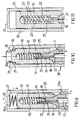
- a first embodiment of a dispenser for fluid cosmetic products is generally indicated 1 in figures 1 to 7.
- the dispenser 1 (figure 1) comprises an elongate, cylindrical container 2 which has a dispensing end 3 and an opposite, bottom end 4.
- the container 2 has a perforated base 5 fixed to the container 2.
- the container 2 has a piston-like structure, housing a plunger 6 of flexible plastics material, which is forced against the internal walls of the container 2 and is movable along it.
- the dispenser 1 has suction means for the cosmetic product, the means being constituted by a positive-displacement pump structure 7 fixed inside the container 2.
- the pump structure 7 comprises (figure 2) a housing 8 fixed to the walls of the container 2, a fixed portion 9 and a movable portion 10, both housed in the housing 8 which defines a chamber 11 of variable volume for holding a predetermined quantity of fluid cosmetic product.
- the two substantially cylindrical portions 9, 10 are disposed one inside the other and form between them a seal with respect to air and with respect to the cosmetic product.
- the movable portion 10 is housed inside the fixed portion 9 and is free to move along a straight path defined by the relative positions of the two portions, parallel to the axis of the cylindrical container 2.
- the movable portion 10 could be constituted by a deformable element, for example, such as a bellows or balloon housed inside or outside the fixed portion 9.
- the non-return valve 12 is conventionally of the type comprising a small ball 13 imprisoned in an antechamber 13a for closing against an inlet hole 14 opening into the container 2.
- the plunger 6, the fixed portion 9 of the positive-displacement pump structure 7, and the container 2 define an airtight space 15 to which the mascara, indicated M below, is admitted.
- the plunger 6 can move as a result of the suction of the said quantity of mascara M from the airtight space by means of the pump structure 7.
- the lubricating effect of the product M on the walls of the container 2 contribute to the operation of the plunger 6.
- the plunger 6 is made of smooth polyethylene which adheres perfectly to the walls of the container 2 with minimal friction.
- a wide range of semi-rigid materials of rubbery consistency may, however, be used.
- the plunger 6 has a disc 60 perpendicular to the axis of the container 2, concentric therewith and having a diameter smaller than the inside diameter of the container 2.
- Tapered walls 61, 62 facing towards the dispensing end 3 and towards the bottom end 4, respectively, are connected to the edge of the disc 60.
- the tapered walls 61, 62 terminate in a double rim 63 which is forced against the container 2.
- the tapered, dished shape conferred on the plunger 6 by the tapered wall 61 and by the disc 60 is particularly effective in achieving a better seal.
- both the internal pressure of the cosmetic product M and the dynamic friction between the corresponding rim 63 and the container 2 act outwardly on the tapered wall 61. Both of the forces help to force the slightly resilient tapered wall 61 more effectively against the internal wall of the container 2.
- the opposite conical wall 62 ensures a second sealing point and makes the plunger 6 symmetrical, facilitating its mounting.
- the movable portion 10 faces outwardly of the container 2 and is housed inside the housing 8.
- the movable portion 10 comprises a pressure pad 65 of rigid structure facing towards the chamber 11 and associated with a first resilient element 16 which, in the present embodiment as well as in the following embodiments, consists of a helical spring extending between the fixed portion 9 and the movable portion 10 adjacent the compression pad 65.
- the housing 8 is force-fitted inside the container 2 and the fixed portion 9 in turn is force fitted in the housing 8.
- the movable portion 10 (figures 2 and 5 to 6) also has a rigid tube 17 which projects from the housing 8 coaxially with the container 2.
- the tube 17 communicates with the chamber 11 of variable volume.
- the tube 17 extends through a hole 66 in the pad 65 as far as the chamber 11 and, in order to achieve better impact-resistance of the tube 17 and to provide the movable portion 10 with an intrinsic resilience, is connected to the pad 65 by means of a second resilient element 67 which is preferably a helical spring.
- the pump 7 operates in conventional manner. Pressure on the movable portion 10 causes the chamber 11 to be emptied through the tube 17 whilst the non-return valve is closed.
- the tube 17 is closed by the product M.
- the dispenser 1 also comprises a bell-like structure 18 (figure 1) which, in the closure position, is associated with the dispensing end 3 of the container 2 with its concave portion 18a facing towards the pump structure 7.
- the concave portion 18a (figures 5 to 7) houses the tube 17 which is structurally independent of the bell-like structure 18.
- the tube 17 also has an end outlet portion 24 on which the bell-like structure 18 bears.
- Figures 1 to 12 show a mascara applicator having a spiral shape forming a series of projections and recesses in which the mascara M to be applied is housed.
- the bell-like structure 18 has a duct 21 (figures 5 to 7) for dispensing mascara M, extending between a dispensing hole 22, disposed in the vicinity of the applicator 20 at the base of the rod 19, and an inlet hole 23 inside the bell-like structure 18.
- the inlet hole 23 opposite the dispensing hole of the duct 21 is positioned adjacent the outlet portion 24 of the tube 17 in order to form a path for the cosmetic product M between the space 15 inside the container 2 and the applicator 20.
- the bell-like structure 18 is housed inside the container 2 at its dispensing end 3, and is free to move, as a result of the operation of actuator means 30 of the dispenser 1 which will be described below, in opposition to the helical spring 16, between a position in which the chamber of variable volume is compressed and a position in which the chamber 11 has a maximum volume.
- the dispenser 1 comprises a substantially cylindrical, hollow closure cap 25 (figure 3) which has a top end 26 and an entry end 27, and which is intended to be associated with the cylindrical container 2, at the dispensing end 3, and to be fitted on the applicator 20.
- the dispenser 1 comprises means 28 for fixing the cap 25 to the container 2, at the dispensing end 3.
- the fixing means 28 comprise a bayonet coupling (figure 1) which has a pin 29 projecting from the container 2, at the end 3, for engagement in a corresponding L-shaped groove 31 formed inside the cap 25.
- the dispenser 1 comprises actuating means 30 which can be operated by the user of the dispenser 1 in order to dispense a quantity of cosmetic product M in the vicinity of the applicator 20.
- the actuating means 30 comprise a capsule 32 (figures 3 and 4) housed inside the cap 25 and structurally independent thereof.
- the capsule 32 is cylindrical and a space 33 is defined inside it.
- the capsule 32 is open adjacent the entry end 27 of the cap 25 so that, when the cap 25 is closed onto the cylindrical container 2, the applicator 20 can be housed inside the space 33 which fits it so as to eliminate unnecessary empty spaces between the surface defined by the applicator 20 and the internal walls of the space 33.
- the capsule 32 is free to move inside the hollow cap 25 along a path parallel to the axis of the cylindrical container 2, the path being defined by the cap 25.
- the capsule 32 When the cap 25 is disposed on the dispensing end 3, the capsule 32 is in abutment with the outer surface of the bell-like structure 18 and is intended to be urged against it, in opposition to the helical spring 16, with a movement such as to cause compression of the chamber 11 of variable volume of the positive-displacement pump structure 7 and, when released, to cause the cosmetic product M to be drawn from the space 15 in the container 2 into the chamber 11 which returns to its maximum volume, as a result of the extension of the helical spring 16.
- subsequent pressure causes the cosmetic product M to be dispensed through the tube 17, the outlet portion 24, the duct 21 and the dispensing hole 22 in the vicinity of the applicator 20 inside the space 33, causing the product M to be absorbed or caught by the applicator 20.
- the actuating means 30 also comprise a plurality of straight grooves 34 on the top of the capsule 32, parallel to the axis of the container 2 and facing towards the internal surface of the cap 25 for engagement by a corresponding plurality of rib-like projections 35 parallel to the axis of the container 2, formed integrally with the cap 25 and projecting from its interior in the vicinity of the top end 26.
- the cap 25 Since it is structurally independent of the capsule 32, once it is released by the bayonet coupling 28, the cap 25 is free to slide axially and to rotate relative to the capsule between a closure position in which the projections 35 are disposed in the grooves 34 and the cap 25 can cooperate with the fixing means 28 and a dispensing position, in which the projections 35 are offset from the grooves 34 and interfere with the cap 32 which can be urged against the bell-like structure 18 by means of a suitable pressure applied manually to the cap 25, causing compression of the chamber 11 of the positive-displacement pump structure 7 and consequent dispensing of the cosmetic product M contained therein.
- the actuating means 30 also comprise a spring 36 (figure 4) disposed in the cavity 37 defined by the top end 26 of the cap 25 and the capsule 32.
- the ends of the spring 36 are fixed to the top end 26 and to the capsule 32, respectively, so as to permit limited relative rotation between the cap 25 and the capsule 32 and so as to facilitate the lifting of the cap 25 from the capsule 32 when the bayonet coupling 28 is released, with consequent disengagement of the grooves 34 and the projections 35.
- the projections 35 are disengaged from the corresponding grooves 34 (figure 6) by the release of the cap 25 by the bayonet coupling 28 and its rotation relative to the capsule 32, which is braked by the friction between it and the inclined surface of the bell-like structure 18.
- the release of the cap 25 allows the chamber 11 to expand and the mascara M flows into it through the valve 12.
- the plunger 6 advances along the container 2 by a volume corresponding to the maximum volume of the chamber 11.
- the perforated base 5 allows air to pass into the cylindrical container 2 into the space left free during the movement of the plunger 6 towards the dispensing end 3.
- the operation may be repeated so as to fill the space 33 completely, ensuring precise metering of the product M.
- the seal between the capsule 32 and the bell-like structure 18 is such as to permit leakage of the air previously contained in the space 33.
- the cap 25 can be fixed to the container 2 and the applicator 20 remains clean and ready for a subsequent application.
- a second embodiment of the dispenser 1 according to the invention will be described below with reference to figures 8 and 9. Only the differences with respect to the previous embodiment, which relate to the fixing means 28 and the actuating means 30, will be described. The rest of the reference numerals remain unchanged.
- the fixing means 28 between the cap 25 and the cylindrical container 2 comprise a male and female screw coupling which has multi-start screw threads 29a on the container 2 and on the cap 25.
- the threads 29a are part of the actuating means 30 which also comprise the above-described spring, indicated 36a, which is stiffer than the resilient element 16 contained in the pump structure 7.
- the capsule 32 interferes with the cap which, owing to the stiffness of the spring 36a, urges it into abutment with the bell-like structure 18, causing compression of the chamber of the positive-displacement pump structure 7, and dispensing of the cosmetic product M during the closure of the dispenser 1 (figure 9).
- the chamber 11 is compressed by the closure of the dispenser 1.
- the chamber 11 is initially empty, it suffices to remove the cap 25, causing the chamber 11 to expand and to be filled with mascara M and to close the dispenser 1 again with the cap 25, compressing the chamber 11 again and consequently dispensing the mascara M in the vicinity of the applicator 20 (figure 9).
- variable volume of the chamber 11 will preferably correspond to a full dose to the applicator 20, in relation to the volume of the space 33.
- the closure of the dispenser 1 causes a full dose of mascara M to be dispensed onto the applicator 20, ready for the next application of mascara M which can be carried out simply by the removal of the cap 25.
- the presence of the spring 36a prevents the fixed portion 10 of the pump structure 7 from being pressed with too great a force during the closure of the dispenser 1 and permits controlled and gradual dispensing into the space 33 in the capsule 32.
- the fixing means 28 comprise a pressure fixing.
- the actuating means 30 comprise a through hole 26a in the top end 26 of the cap 25 and a push-button 38 formed integrally on the top of the capsule 32 and projecting from the top end 26 of the cap 25 through the through hole 26a.
- the push-button 38 is intended to be pressed, causing compression of the chamber 11 of the pump structure 7 and consequent dispensing of the cosmetic product M in the vicinity of the applicator.
- This step should advantageously be performed with the cap 25 closed on the container 2. Application then takes place by the release and removal of the cap 25.
- bayonet coupling, screw coupling and pressure fixing means 28 described are structurally and functionally interchangeable on the various embodiments of the dispenser, irrespective of from the actuating means 30 used and described.
- Figure 11 shows the upper end of a dispenser 1 according to the invention in which the tube 21 extends from the bell-like structure 18 into the interior of the rod 19 which is hollow and has a plurality of dispensing holes 22 spaced uniformly inside the applicator 20 and in communication with the duct 21.
- a further variant may be constituted by the formation of the tube 17 and the bell-like structure as a single integral structure in which they constitute a single piece.
- the applicator 20 may have shapes other than that shown in figure 12.
- Figure 13 shows an applicator 20, typically for mascara, constituted by a plurality of discs piled up and supported by the rod 19. It is suitable for making-up eyelashes.
- Figure 14 shows an applicator 20 in the form of a small comb with a plurality of springs 41 which project from the rod 19. This is also suitable for the eyelashes.
- the applicator 20 has two opposed faces, indicated 39a and 39b, respectively, arranged longitudinally relative to the rod 19.
- a first face 39a is formed as a comb and the other is formed substantially as an applicator for mascara M similar to that shown in figure 12.
- Figure 16 shows an applicator 20 formed as a brush. It is suitable, for example, for making-up the eyelids, the regions surrounding the eyes, the lips, and the nails by the deposition of a coloured product.
- Figure 17 shows an applicator 20 comprising a spongy and absorbent pad 40 with a soft structure suitable, for example, for making-up the skin of the face in order to hide blemishes by means of a coloured product, or for making-up the lips.
- Figure 18 shows an absorbent pad 40 with a rigid structure, for example, made of felt.
- Figure 19 shows a conventional mascara brush or pencil with bristles 42 which project radially from the rod 19.
- This may be used, for example, for making-up the eyes or the lips by the tracing of coloured lines.
- All of the cosmetic products suitable for application as shown are either liquid or pasty fluid cosmetic products which may even have high viscosity.
- the container which houses the cosmetic product is airtight and the product is therefore not subject to drying or oxidation and does not deteriorate during the entire useful life of the dispenser.
- the metering takes place precisely and in a reproducible manner over time by a volumetric principle determined both by the type of suction means and by the space inside the capsule, irrespective of the quantity of product remaining in the container.
- This metering takes place in a closed and protected environment, so that splashes, spills and the like which might soil the user are prevented.
- this dispenser is suitable for very many types of greatly differing cosmetic products, the structure remaining substantially unchanged even for different methods of application or parts of the face to be made up.
- the container which itself is elongate and thus convenient to grip like a pencil, performs the function of the handle of the applicator, considerably improving the ergonomic characteristics of the dispenser.
- This advantage also enables the cap to be kept within suitable dimensions without the need to lengthen it.
Priority Applications (2)
| Application Number | Priority Date | Filing Date | Title |
|---|---|---|---|
| EP19960830631 EP0855155B1 (de) | 1996-12-18 | 1996-12-18 | Spender für kosmetische Produkte |
| DE69635553T DE69635553D1 (de) | 1996-12-18 | 1996-12-18 | Spender für kosmetische Produkte |
Applications Claiming Priority (1)
| Application Number | Priority Date | Filing Date | Title |
|---|---|---|---|
| EP19960830631 EP0855155B1 (de) | 1996-12-18 | 1996-12-18 | Spender für kosmetische Produkte |
Publications (2)
| Publication Number | Publication Date |
|---|---|
| EP0855155A1 true EP0855155A1 (de) | 1998-07-29 |
| EP0855155B1 EP0855155B1 (de) | 2005-12-07 |
Family
ID=8226079
Family Applications (1)
| Application Number | Title | Priority Date | Filing Date |
|---|---|---|---|
| EP19960830631 Expired - Lifetime EP0855155B1 (de) | 1996-12-18 | 1996-12-18 | Spender für kosmetische Produkte |
Country Status (2)
| Country | Link |
|---|---|
| EP (1) | EP0855155B1 (de) |
| DE (1) | DE69635553D1 (de) |
Cited By (6)
| Publication number | Priority date | Publication date | Assignee | Title |
|---|---|---|---|---|
| FR2832599A1 (fr) * | 2001-11-29 | 2003-05-30 | Benson Srl | Distributeur de produit cosmetique en materiau barriere |
| EP1342428A1 (de) * | 2002-03-05 | 2003-09-10 | L'oreal | Vorrichtung zum Kämmen und/oder Bürsten von Wimpern und/oder Augenbrauen und/oder zum Auftragen auf diese |
| FR2837077A1 (fr) * | 2002-03-13 | 2003-09-19 | Oreal | Dispositif pour peigner les cils et/ou les sourcils et/ou appliquer un produit sur ceux-ci |
| DE202004014687U1 (de) * | 2004-09-21 | 2006-02-09 | Schwan-Stabilo Cosmetics Gmbh & Co. Kg | Auftragvorrichtung |
| WO2015199750A1 (en) | 2014-06-26 | 2015-12-30 | E. I. Du Pont De Nemours And Company | Ethylene acid copolymers, their ionomers, and their use in packaging films and injection molded articles |
| KR20180080143A (ko) * | 2017-01-03 | 2018-07-11 | 주식회사 엘지생활건강 | 마스카라 |
Families Citing this family (3)
| Publication number | Priority date | Publication date | Assignee | Title |
|---|---|---|---|---|
| AU2009308728B2 (en) | 2008-10-31 | 2016-02-04 | Performance Materials Na, Inc. | High-clarity ionomer compositions and articles comprising the same |
| JP5712141B2 (ja) | 2008-12-30 | 2015-05-07 | イー・アイ・デュポン・ドウ・ヌムール・アンド・カンパニーE.I.Du Pont De Nemours And Company | 高透明度のブレンドイオノマー組成物およびそれを含む物品 |
| JP5587336B2 (ja) | 2008-12-31 | 2014-09-10 | イー・アイ・デュポン・ドウ・ヌムール・アンド・カンパニー | 曇り度が低く防水性の高いアイオノマー組成物及びそれを含む物品 |
Citations (7)
| Publication number | Priority date | Publication date | Assignee | Title |
|---|---|---|---|---|
| EP0208394A2 (de) * | 1985-07-11 | 1987-01-14 | Yoshino Kogyosho Co., Ltd. | Behälterartiges Toilettengerät |
| FR2598300A1 (fr) * | 1986-05-12 | 1987-11-13 | Dreystadt Stephane | Brosse a dents integrant un reservoir de dentifrice et un dispositif doseur et un dispositif diffuseur |
| US5002415A (en) * | 1988-06-30 | 1991-03-26 | L'oreal | Applicator set for eyelash makeup, including a cake of mascara and a moistened distributor element |
| DE9004068U1 (de) * | 1990-04-07 | 1991-08-01 | Rotring-Werke Riepe Kg, 2000 Hamburg, De | |
| DE4105294A1 (de) * | 1990-02-23 | 1991-09-05 | Mitsubishi Pencil Co | Fluessigkeitsauftraeger |
| EP0601192A1 (de) * | 1992-06-02 | 1994-06-15 | GARCIA RODRIGUEZ, Manuel | Verschluss zum dosieren und auftragen von nagellack |
| US5339841A (en) * | 1992-01-24 | 1994-08-23 | L'oreal | Makeup device |
-
1996
- 1996-12-18 DE DE69635553T patent/DE69635553D1/de not_active Expired - Fee Related
- 1996-12-18 EP EP19960830631 patent/EP0855155B1/de not_active Expired - Lifetime
Patent Citations (7)
| Publication number | Priority date | Publication date | Assignee | Title |
|---|---|---|---|---|
| EP0208394A2 (de) * | 1985-07-11 | 1987-01-14 | Yoshino Kogyosho Co., Ltd. | Behälterartiges Toilettengerät |
| FR2598300A1 (fr) * | 1986-05-12 | 1987-11-13 | Dreystadt Stephane | Brosse a dents integrant un reservoir de dentifrice et un dispositif doseur et un dispositif diffuseur |
| US5002415A (en) * | 1988-06-30 | 1991-03-26 | L'oreal | Applicator set for eyelash makeup, including a cake of mascara and a moistened distributor element |
| DE4105294A1 (de) * | 1990-02-23 | 1991-09-05 | Mitsubishi Pencil Co | Fluessigkeitsauftraeger |
| DE9004068U1 (de) * | 1990-04-07 | 1991-08-01 | Rotring-Werke Riepe Kg, 2000 Hamburg, De | |
| US5339841A (en) * | 1992-01-24 | 1994-08-23 | L'oreal | Makeup device |
| EP0601192A1 (de) * | 1992-06-02 | 1994-06-15 | GARCIA RODRIGUEZ, Manuel | Verschluss zum dosieren und auftragen von nagellack |
Cited By (8)
| Publication number | Priority date | Publication date | Assignee | Title |
|---|---|---|---|---|
| FR2832599A1 (fr) * | 2001-11-29 | 2003-05-30 | Benson Srl | Distributeur de produit cosmetique en materiau barriere |
| WO2003045186A1 (fr) * | 2001-11-29 | 2003-06-05 | Benson S.R.L. | Distributeur de produit cosmetique en materiau barriere |
| EP1342428A1 (de) * | 2002-03-05 | 2003-09-10 | L'oreal | Vorrichtung zum Kämmen und/oder Bürsten von Wimpern und/oder Augenbrauen und/oder zum Auftragen auf diese |
| FR2837077A1 (fr) * | 2002-03-13 | 2003-09-19 | Oreal | Dispositif pour peigner les cils et/ou les sourcils et/ou appliquer un produit sur ceux-ci |
| DE202004014687U1 (de) * | 2004-09-21 | 2006-02-09 | Schwan-Stabilo Cosmetics Gmbh & Co. Kg | Auftragvorrichtung |
| WO2015199750A1 (en) | 2014-06-26 | 2015-12-30 | E. I. Du Pont De Nemours And Company | Ethylene acid copolymers, their ionomers, and their use in packaging films and injection molded articles |
| US10377840B2 (en) | 2014-06-26 | 2019-08-13 | E.I. Du Pont De Nemours And Company | Ethylene acid copolymers, their ionomers, and their use in packaging films and injection molded articles |
| KR20180080143A (ko) * | 2017-01-03 | 2018-07-11 | 주식회사 엘지생활건강 | 마스카라 |
Also Published As
| Publication number | Publication date |
|---|---|
| DE69635553D1 (de) | 2006-01-12 |
| EP0855155B1 (de) | 2005-12-07 |
Similar Documents
| Publication | Publication Date | Title |
|---|---|---|
| US6648538B2 (en) | Dispensing device and method, and refill for a dispensing device | |
| US7125189B2 (en) | Device, system, and method for applying a product | |
| JP2879573B2 (ja) | 化粧品塗布器具セット | |
| CA1309381C (en) | Topical applicator for liquid | |
| US4244525A (en) | Writing instrument with refillable scent dispenser | |
| JP3431938B2 (ja) | 化粧具 | |
| JP3490057B2 (ja) | 液状製品の収容供給ユニット | |
| US4838722A (en) | Device for dispensing flowable substances | |
| US6776549B2 (en) | Device and method for applying a product | |
| EP0390922B1 (de) | Flüssigkeitsauftragegerät | |
| US4692047A (en) | Brush for applying material in liquid or emulsion form | |
| US4189245A (en) | Suction producing disposable pump and dispenser | |
| EP0284166A2 (de) | Bürste | |
| US4040753A (en) | Applicator instrument | |
| KR200439672Y1 (ko) | 도포 팁 교체 사용이 가능한 내용물 정량 배출 용기 | |
| EP0855155B1 (de) | Spender für kosmetische Produkte | |
| KR880001673B1 (ko) | 유액이 자체내에서 공급되도록 된 브러시 | |
| JPWO2005089588A1 (ja) | 塗布体付き容器 | |
| GB2132883A (en) | Self-propelled cosmetic applicator | |
| KR102209696B1 (ko) | 선택적 토출이 가능한 두피 관리용 화장품용기 | |
| JP2017531480A (ja) | アプリケーターおよびメークアップ製品のディスペンサーを含むメークアップアイテム | |
| KR20070092087A (ko) | 파우더 토출이 용이한 화장품 용기 | |
| JP2004065467A (ja) | 高粘度流動性化粧品を塗布するための化粧用具 | |
| GB2422301A (en) | Cosmetic applicator having wiper | |
| KR20200042546A (ko) | 2개의 화장품을 도포하기 위한 캡 및 바이알 어플리케이터 시스템 |
Legal Events
| Date | Code | Title | Description |
|---|---|---|---|
| PUAI | Public reference made under article 153(3) epc to a published international application that has entered the european phase |
Free format text: ORIGINAL CODE: 0009012 |
|
| 17P | Request for examination filed |
Effective date: 19980302 |
|
| AK | Designated contracting states |
Kind code of ref document: A1 Designated state(s): BE DE ES FR GB IT NL |
|
| AX | Request for extension of the european patent |
Free format text: AL;LT;LV;RO;SI |
|
| 17Q | First examination report despatched |
Effective date: 19980826 |
|
| AKX | Designation fees paid |
Free format text: BE DE ES FR GB IT NL |
|
| RBV | Designated contracting states (corrected) |
Designated state(s): BE DE ES FR GB IT NL |
|
| RAP3 | Party data changed (applicant data changed or rights of an application transferred) |
Owner name: BENSON S.R.L. |
|
| RAP1 | Party data changed (applicant data changed or rights of an application transferred) |
Owner name: BENSON S.R.L. |
|
| RAP1 | Party data changed (applicant data changed or rights of an application transferred) |
Owner name: BENSON S.P.A. |
|
| GRAP | Despatch of communication of intention to grant a patent |
Free format text: ORIGINAL CODE: EPIDOSNIGR1 |
|
| GRAS | Grant fee paid |
Free format text: ORIGINAL CODE: EPIDOSNIGR3 |
|
| GRAA | (expected) grant |
Free format text: ORIGINAL CODE: 0009210 |
|
| AK | Designated contracting states |
Kind code of ref document: B1 Designated state(s): BE DE ES FR GB IT NL |
|
| PG25 | Lapsed in a contracting state [announced via postgrant information from national office to epo] |
Ref country code: NL Free format text: LAPSE BECAUSE OF FAILURE TO SUBMIT A TRANSLATION OF THE DESCRIPTION OR TO PAY THE FEE WITHIN THE PRESCRIBED TIME-LIMIT Effective date: 20051207 Ref country code: IT Free format text: LAPSE BECAUSE OF FAILURE TO SUBMIT A TRANSLATION OF THE DESCRIPTION OR TO PAY THE FEE WITHIN THE PRE;WARNING: LAPSES OF ITALIAN PATENTS WITH EFFECTIVE DATE BEFORE 2007 MAY HAVE OCCURRED AT ANY TIME BEFORE 2007. THE CORRECT EFFECTIVE DATE MAY BE DIFFERENT FROM THE ONE RECORDED.SCRIBED TIME-LIMIT Effective date: 20051207 Ref country code: BE Free format text: LAPSE BECAUSE OF FAILURE TO SUBMIT A TRANSLATION OF THE DESCRIPTION OR TO PAY THE FEE WITHIN THE PRESCRIBED TIME-LIMIT Effective date: 20051207 |
|
| REG | Reference to a national code |
Ref country code: GB Ref legal event code: FG4D |
|
| REF | Corresponds to: |
Ref document number: 69635553 Country of ref document: DE Date of ref document: 20060112 Kind code of ref document: P |
|
| PG25 | Lapsed in a contracting state [announced via postgrant information from national office to epo] |
Ref country code: GB Free format text: LAPSE BECAUSE OF NON-PAYMENT OF DUE FEES Effective date: 20060307 |
|
| PG25 | Lapsed in a contracting state [announced via postgrant information from national office to epo] |
Ref country code: ES Free format text: LAPSE BECAUSE OF FAILURE TO SUBMIT A TRANSLATION OF THE DESCRIPTION OR TO PAY THE FEE WITHIN THE PRESCRIBED TIME-LIMIT Effective date: 20060318 |
|
| NLV1 | Nl: lapsed or annulled due to failure to fulfill the requirements of art. 29p and 29m of the patents act | ||
| PG25 | Lapsed in a contracting state [announced via postgrant information from national office to epo] |
Ref country code: DE Free format text: LAPSE BECAUSE OF NON-PAYMENT OF DUE FEES Effective date: 20060701 |
|
| ET | Fr: translation filed | ||
| PLBE | No opposition filed within time limit |
Free format text: ORIGINAL CODE: 0009261 |
|
| STAA | Information on the status of an ep patent application or granted ep patent |
Free format text: STATUS: NO OPPOSITION FILED WITHIN TIME LIMIT |
|
| 26N | No opposition filed |
Effective date: 20060908 |
|
| GBPC | Gb: european patent ceased through non-payment of renewal fee |
Effective date: 20060307 |
|
| PGFP | Annual fee paid to national office [announced via postgrant information from national office to epo] |
Ref country code: FR Payment date: 20120118 Year of fee payment: 16 |
|
| REG | Reference to a national code |
Ref country code: FR Ref legal event code: ST Effective date: 20130830 |
|
| PG25 | Lapsed in a contracting state [announced via postgrant information from national office to epo] |
Ref country code: FR Free format text: LAPSE BECAUSE OF NON-PAYMENT OF DUE FEES Effective date: 20130102 |