EP0854334A1 - Container for receiving carbon dioxide snow - Google Patents
Container for receiving carbon dioxide snow Download PDFInfo
- Publication number
- EP0854334A1 EP0854334A1 EP98400026A EP98400026A EP0854334A1 EP 0854334 A1 EP0854334 A1 EP 0854334A1 EP 98400026 A EP98400026 A EP 98400026A EP 98400026 A EP98400026 A EP 98400026A EP 0854334 A1 EP0854334 A1 EP 0854334A1
- Authority
- EP
- European Patent Office
- Prior art keywords
- tank
- injection
- injector
- carbon dioxide
- container
- Prior art date
- Legal status (The legal status is an assumption and is not a legal conclusion. Google has not performed a legal analysis and makes no representation as to the accuracy of the status listed.)
- Withdrawn
Links
Images

Classifications
-
- F—MECHANICAL ENGINEERING; LIGHTING; HEATING; WEAPONS; BLASTING
- F25—REFRIGERATION OR COOLING; COMBINED HEATING AND REFRIGERATION SYSTEMS; HEAT PUMP SYSTEMS; MANUFACTURE OR STORAGE OF ICE; LIQUEFACTION SOLIDIFICATION OF GASES
- F25D—REFRIGERATORS; COLD ROOMS; ICE-BOXES; COOLING OR FREEZING APPARATUS NOT OTHERWISE PROVIDED FOR
- F25D3/00—Devices using other cold materials; Devices using cold-storage bodies
- F25D3/12—Devices using other cold materials; Devices using cold-storage bodies using solidified gases, e.g. carbon-dioxide snow
- F25D3/125—Movable containers
-
- C—CHEMISTRY; METALLURGY
- C01—INORGANIC CHEMISTRY
- C01B—NON-METALLIC ELEMENTS; COMPOUNDS THEREOF; METALLOIDS OR COMPOUNDS THEREOF NOT COVERED BY SUBCLASS C01C
- C01B32/00—Carbon; Compounds thereof
- C01B32/50—Carbon dioxide
- C01B32/55—Solidifying
Definitions
- the present invention relates to a container for receiving carbon dioxide snow of the type comprising, on the one hand, injection means adapted to cooperate with an injector connected to a source of liquid CO 2 and to allow the injection of carbon dioxide snow into the container. , and, on the other hand, in the upper face of the tank, means for evacuating the gaseous CO 2 formed during said injection.
- Such bins are particularly intended storage and transport of products fresh food.
- bins are sometimes removable and have an open upper face to receive the loading of dry ice from a dry ice container in bulk, or directly a carbon dioxide snow projection torch.
- This type of loading is delicate, not very rational and causes significant losses in dry ice. In addition, it does not allow the quantity of dry ice to specific needs that may require conservation of particular products.
- the tank described in this last document comprises, on the one hand, an injection ramp comprising injection or expansion ports for liquid CO 2 , which can be connected to a liquid CO 2 injector, and a deflector.
- an injection ramp comprising injection or expansion ports for liquid CO 2 , which can be connected to a liquid CO 2 injector, and a deflector.
- it includes in its upper surface a grid for evacuating the gaseous CO 2 produced during the formation of the carbon dioxide snow.
- This grid prevents the carbon dioxide snow formed from escaping from the tank and allows, after loading the tank, the evacuation of the gaseous CO 2 formed by sublimation of the carbon dioxide snow.
- the injection ramp is arranged along a lateral face of the tank and allows a relatively uniform filling thereof. The main drawback of such an arrangement is its high cost.
- Another embodiment described in the same document comprises an injection box which can be adapted directly to a loading face of a container.
- the tank described also has a grid for evacuating CO 2 gas and retaining dry ice, mounted in the upper face of the tank.
- This embodiment has the drawback of requiring the production of as many injection boxes as there are different sizes of tanks.
- the object of the present invention is to provide a tank which, on the one hand, allows rapid, modular loading, requiring minimum handling and reducing CO 2 losses, and, on the other hand, is simple to carry out and therefore reduced production cost.
- the subject of the invention is a container of the aforementioned type, characterized in that the injection means are adapted to orient the injection of dry ice approximately tangentially to a side wall of the container so as to create a vortex in the tank, and in that the means for evacuating the gaseous CO 2 produced during the injection of carbon dioxide snow are located in the central region of said vortex.
- the subject of the invention is also a low temperature storage enclosure of products, of the type with a storage volume thermally insulated and at least one snow bin carbonic suitable for refrigerating this volume, characterized in that the bin is a bin as defined above.
- the subject of the invention is finally an installation for the conservation at low temperature of products, of the type comprising an enclosure for the conservation at low temperature of products comprising a storage volume and at least one container for receiving dry ice adapted to refrigerate this volume, a source of liquid CO 2 under pressure, and an injector connected to this source, adapted to be connected to the tank and provided with a distribution valve connected to control means, characterized in that the enclosure is an enclosure such that defined above.
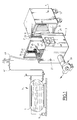
- the installation shown in FIG. 1 comprises an enclosure 1 for low-temperature storage of products as described in the document EP-A-337 860 mentioned above, a device 3 for loading dry ice and a source 5 of liquid CO 2 .
- the liquid CO 2 is contained in a tank 7 under determined pressure and temperature conditions, maintained by a refrigeration unit 9, typically between 18 and 20 bars relative and at -20 ° C.
- Enclosure 1 is an insulated container of mobile parallelepiped shape on casters 12. It includes a front access door not shown, and a container 11 for receiving the dry ice.
- the tray 11, parallelepiped and flat in shape, is consisting of a bowl 14 and a cover 16. It is suspended, by means of fixing lugs 13 evenly distributed on the side faces of the bowl and, for example, a bolting system, in the upper part of the inner chamber 15 of enclosure 1. The lower part of this room 15 forms a storage volume for products thermally insulated.
- Enclosure 1 further includes a screen thermal 17 removable, in the form of a horizontal plate, suspended from the tank 11 by means of lugs 19 ( Figure 2). This screen extends away from the underside of the tray 11 and separates the latter from the storage volume.
- the front face of the tank 11 is provided with a dry ice injection port 21, suitable to receive the head of a snow injector carbonic. This hole is adjacent to the face left side of bin 11, which is one of two large side faces of the tank.
- a magnetic plate 23 is also fixed, by gluing or otherwise, to near orifice 17 to allow the temporary securing of the tank and a injector dry ice.
- the upper face of the tank 11 has a circular orifice 25 for evacuating the gaseous CO 2 formed during the injection of carbon dioxide snow.
- This orifice 25 also serves as a means of evacuation of the gaseous CO2 formed during the sublimation of the carbon dioxide snow.
- the loading device 3 comprises an injector 31 of dry ice and an articulated awning structure 23.
- This structure 27 is provided with two deployable lateral leaves 29. It is intended to be positioned opposite the front face of the enclosure 1, which is the loading face in dry ice.
- the injector 31 is suspended by means 33 of elastic suspension from a gantry 35 secured to the deployed structure 27.
- the suspension means 33 can be moved along the gantry 35 by means of a carriage 37.
- the structure 27 is also connected to a discharge device 39 comprising a blower.
- the structure 27, as described in the aforementioned application EP-A-631 096, is intended to form a receptacle for confining the CO 2 gas formed during the loading of the tank with carbon dioxide snow.
- a pipe 41 for supplying liquid CO 2 leaves from the reservoir 7. It is extended by a hose 43 connected to the injector 31.
- the injector 31 in the form of a pistol, is a dry ice injector. Its head has means for expanding the liquid CO 2 and for forming carbon dioxide snow, namely a calibrated orifice (not visible in the drawings) and an outlet nozzle 45 of cylindrical shape with horizontal axis.
- the injector 31 further comprises a distribution solenoid valve, not shown, which makes it possible to dose the quantity of expanded liquid CO 2 and therefore of the carbon dioxide snow formed.
- the solenoid valve is connected by suitable wiring 47 to control means 49.
- a magnetic socket 51 is fixed on the outer surface of the nozzle 45, parallel to its main axis. It ensures solidarity temporary injector 31 and tank 11 cooperating with the magnetic plate 23.
- the carriage 37 and the means 33 allow bring the injector 31 to the right of the orifice 21 and insert nozzle 45 into the tank through this orifice.
- Magnetic plate 23 and socket magnetized 51 are positioned so as to come then in contact and, thus, ensure the joining temporary injector 31 and tank 11.
- the start and duration of loading are controlled via the solenoid valve by means 49 of ordered.
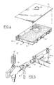
- the loading of the bin is illustrated by the Figures 3 and 4.
- the liquid CO 2 is expanded in the nozzle 45, which produces a carbon dioxide snow jet substantially tangent to the left lateral face of the container 11.
- the carbon dioxide snow impacts the rear face of the container, then is deflected along the latter until it impacts the right side face of the tank 11.
- the jet is then deflected along this right side face. It then impacts the front face of the tank 11 at its right end, before being deflected again towards the left end of this front face, where it meets the jet emerging from the nozzle 45.
- the gaseous CO 2 formed is concentrated in the central part of the vortex and rises from it.
- the discharge port 25 was placed in the region of the vortex centers for the range of injection pressures selected.
- the arrows in FIG. 4 show the evacuation route out of the gaseous CO 2 tank. This configuration eliminates the presence of a carbon dioxide retaining grid, since the segregation of gases and snow particles occurs naturally within the vortex.
- the container according to the invention therefore allows to obtain a satisfactory filling of the snow container carbon dioxide, as shown in Figure 4.
- the socket 51 and the plate 23 are adapted so that, on the one hand, the decline in the injector 31 when loading the tank does not cause not the separation of the tank 11 and the injector 31, and on the other hand, so that an operator is capable to separate the tank 11 and the injector 31 manually.
- FIG. 5 illustrates another mode of realization of the invention, which differs from the previous one with the following points.
- the tank comprises means 53 for connection to an injector 55 of liquid CO 2 , of the "quick coupling" type, and means for injecting carbon dioxide snow into the tank comprising means for expanding liquid CO 2 and for forming snow. carbonic.
- These means include a calibrated orifice for CO 2 expansion (not visible in the drawing), and a cylindrical nozzle 57 for injection into the bowl 14 of the dry ice formed.
- the calibrated orifice and the nozzle 57 are therefore integral with the tank 11.
- the nozzle 57 is identical to the nozzle 45 of Figures 1 to 3 and oriented in the same way.
- the injector 55 includes a device for manual locking / unlocking which allows temporarily attach to the connection means 53.
- the injector 55 has a manual tap 61 opening / closing downstream of the solenoid valve of the injector. This tap 61 is mechanically coupled to device 59 so as not to allow opening from the tap only when the injector 55 and the tank are properly secured, as described in the request mentioned above EP-A-631 096.
- the other elements of the tank 11 of the injector 55 are identical in all respects to those of the previous embodiment.
- the tank 11 and the injector 55 of FIG. 5 can also be incorporated into an enclosure and an installation as described above.
- the injector 55 is secured thanks to the device 59, and the opening of the gun solenoid valve is controlled by the control means 49.
- the filling mode is then identical to the one described above, creating also a vortex, and therefore presenting the same advantages.
- the invention makes it possible to provide a fast, efficient, modular injection of dry ice, with easy implementation and low CO 2 losses.
- the tank is of reduced cost since it does not have an injection rail or an evacuation grid. It can also be charged by common liquid CO 2 or carbon dioxide snow injectors.
Abstract
Description
La présente invention concerne un bac de réception de neige carbonique du type comprenant, d'une part, des moyens d'injection adaptés pour coopérer avec un injecteur relié à une source de CO2 liquide et permettre l'injection de neige carbonique dans le bac, et, d'autre part, dans la face supérieure du bac, des moyens d'évacuation du CO2 gazeux formé lors de ladite injection.The present invention relates to a container for receiving carbon dioxide snow of the type comprising, on the one hand, injection means adapted to cooperate with an injector connected to a source of liquid CO 2 and to allow the injection of carbon dioxide snow into the container. , and, on the other hand, in the upper face of the tank, means for evacuating the gaseous CO 2 formed during said injection.
Ces bacs sont utilisés dans des enceintes de conservation à basse température de produits pour constituer une source froide. La conservation à basse température des produits est assurée par sublimation de la neige carbonique contenue dans le bac et par transfert convectif dans l'enceinte du CO2 gazeux résultant. De telles enceintes ainsi que le mode de circulation des gaz froids dans celles-ci sont décrits par exemple dans les demandes de brevet EP-A-337 860 et EP-A-591 047.These tanks are used in low temperature product storage chambers to constitute a cold source. The products are stored at low temperature by sublimation of the carbon dioxide snow contained in the tank and by convective transfer into the enclosure of the resulting CO 2 gas. Such enclosures as well as the mode of circulation of the cold gases therein are described for example in patent applications EP-A-337,860 and EP-A-591,047.
De tels bacs sont particulièrement destinés à la conservation et au transport de produits alimentaires frais.Such bins are particularly intended storage and transport of products fresh food.
Diverses solutions ont été proposées pour assurer le chargement en neige carbonique de tels bacs.Various solutions have been proposed for ensure the loading in dry ice of such bins.
Ces bacs sont parfois extractibles et comportent une face supérieure ouverte pour recevoir le chargement de neige carbonique en provenance d'un conteneur de neige carbonique en vrac, ou directement d'une torche de projection de neige carbonique. Ce type de chargement est délicat, peu rationnel et engendre des pertes importantes en neige carbonique. De plus, il ne permet pas d'adapter la quantité de neige carbonique aux besoins précis que peut exiger la conservation de produits particuliers. These bins are sometimes removable and have an open upper face to receive the loading of dry ice from a dry ice container in bulk, or directly a carbon dioxide snow projection torch. This type of loading is delicate, not very rational and causes significant losses in dry ice. In addition, it does not allow the quantity of dry ice to specific needs that may require conservation of particular products.
Un autre type de chargement, décrit dans la demande de brevet EP-A-631 096, permet d'injecter une quantité déterminée de CO2 liquide sous pression de façon à former une masse déterminée de neige carbonique dans le bac.Another type of loading, described in patent application EP-A-631 096, makes it possible to inject a determined quantity of liquid CO 2 under pressure so as to form a determined mass of carbon dioxide snow in the tank.
Le bac décrit dans ce dernier document comprend, d'une part, une rampe d'injection comportant des orifices d'injection et de détente du CO2 liquide, qui peut être raccordée à un injecteur de CO2 liquide, et un déflecteur. D'autre part, il comprend dans sa surface supérieure une grille d'évacuation du CO2 gazeux produit lors de la formation de la neige carbonique. Cette grille empêche la neige carbonique formée de s'échapper du bac et permet, après le chargement du bac, l'évacuation du CO2 gazeux formé par sublimation de la neige carbonique. La rampe d'injection est disposée le long d'une face latérale du bac et permet un remplissage relativement uniforme de celui-ci. L'inconvénient principal d'un tel agencement est son coût élevé.The tank described in this last document comprises, on the one hand, an injection ramp comprising injection or expansion ports for liquid CO 2 , which can be connected to a liquid CO 2 injector, and a deflector. On the other hand, it includes in its upper surface a grid for evacuating the gaseous CO 2 produced during the formation of the carbon dioxide snow. This grid prevents the carbon dioxide snow formed from escaping from the tank and allows, after loading the tank, the evacuation of the gaseous CO 2 formed by sublimation of the carbon dioxide snow. The injection ramp is arranged along a lateral face of the tank and allows a relatively uniform filling thereof. The main drawback of such an arrangement is its high cost.
Un autre mode de réalisation décrit dans le même document comporte un boítier d'injection qui peut s'adapter directement sur une face de chargement d'un bac. Le bac décrit présente également une grille d'évacuation du CO2 gazeux et de retenue de la neige carbonique, montée dans la face supérieure du bac. Ce mode de réalisation présente l'inconvénient de nécessiter la réalisation d'autant de boítiers d'injection qu'il existe de dimensions de bacs différentes.Another embodiment described in the same document comprises an injection box which can be adapted directly to a loading face of a container. The tank described also has a grid for evacuating CO 2 gas and retaining dry ice, mounted in the upper face of the tank. This embodiment has the drawback of requiring the production of as many injection boxes as there are different sizes of tanks.
Le but de la présente invention est de fournir un bac qui, d'une part, permette un chargement rapide, modulable, nécessitant un minimum de manipulations et réduisant les pertes en CO2, et, d'autre part, soit simple à réaliser et donc de coût de production réduit.The object of the present invention is to provide a tank which, on the one hand, allows rapid, modular loading, requiring minimum handling and reducing CO 2 losses, and, on the other hand, is simple to carry out and therefore reduced production cost.
A cet effet, l'invention a pour objet un bac du type précité, caractérisé en ce que les moyens d'injection sont adaptés pour orienter l'injection de neige carbonique à peu près tangentiellement à une paroi latérale du bac de manière à créer un tourbillon dans le bac, et en ce que les moyens d'évacuation du CO2 gazeux produit lors de l'injection de neige carbonique sont localisés dans la région centrale dudit tourbillon.To this end, the subject of the invention is a container of the aforementioned type, characterized in that the injection means are adapted to orient the injection of dry ice approximately tangentially to a side wall of the container so as to create a vortex in the tank, and in that the means for evacuating the gaseous CO 2 produced during the injection of carbon dioxide snow are located in the central region of said vortex.
Suivant des modes particuliers de réalisation, le bac peut comporter une ou plusieurs des caractéristiques suivantes :
- les moyens d'injection comprennent un orifice de réception d'une buse de détente de CO2 liquide et de formation de neige carbonique solidaire de la tête de l'injecteur,
- les moyens d'injection comprennent des moyens de raccordement à l'injecteur, reliés à une buse de détente de CO2 liquide et de génération de neige carbonique, cette buse étant solidaire du bac,
- des moyens de solidarisation temporaire sont prévus pour positionner l'injecteur sur le bac,
- les moyens de solidarisation temporaire comprennent un dispositif de verrouillage/déverrouillage manuel,
- les moyens de solidarisation comprennent un système à aimant,
- les moyens d'évacuation sont constitués par un orifice, notamment circulaire,
- le bac est parallélépipédique et les moyens d'injection sont adjacents et parallèles à une des grandes faces latérales du bac.
- the injection means comprise an orifice for receiving a nozzle for expanding liquid CO 2 and for forming carbon dioxide snow secured to the head of the injector,
- the injection means include means for connecting to the injector, connected to a liquid CO 2 expansion and carbon dioxide generation nozzle, this nozzle being integral with the tank,
- temporary fastening means are provided for positioning the injector on the tank,
- the temporary securing means comprise a manual locking / unlocking device,
- the securing means comprise a magnet system,
- the evacuation means consist of an orifice, in particular circular,
- the tank is parallelepipedal and the injection means are adjacent and parallel to one of the large lateral faces of the tank.
L'invention a également pour objet une enceinte de conservation à basse température de produits, du type comportant un volume de stockage thermiquement isolé et au moins un bac de neige carbonique adapté pour réfrigérer ce volume, caractérisé en ce que le bac est un bac tel que défini ci-dessus.The subject of the invention is also a low temperature storage enclosure of products, of the type with a storage volume thermally insulated and at least one snow bin carbonic suitable for refrigerating this volume, characterized in that the bin is a bin as defined above.
L'invention a finalement pour objet une installation de conservation à basse température de produits, du type comprenant une enceinte de conservation à basse température de produits comportant un volume de stockage et au moins un bac de réception de neige carbonique adapté pour réfrigérer ce volume, une source de CO2 liquide sous pression, et un injecteur relié à cette source, adapté pour être relié au bac et muni d'une vanne de distribution reliée à des moyens de commande, caractérisée en ce que l'enceinte est une enceinte telle que définie ci-dessus.The subject of the invention is finally an installation for the conservation at low temperature of products, of the type comprising an enclosure for the conservation at low temperature of products comprising a storage volume and at least one container for receiving dry ice adapted to refrigerate this volume, a source of liquid CO 2 under pressure, and an injector connected to this source, adapted to be connected to the tank and provided with a distribution valve connected to control means, characterized in that the enclosure is an enclosure such that defined above.
Des exemples de réalisation de l'invention vont maintenant être décrits en regard des dessins annexés sur lesquels :
- la figure 1 est une vue schématique d'une installation de conservation de produits frais selon l'invention,
- la figure 2 est une vue en perspective du bac de réception de neige carbonique de l'installation de la figure 1,
- les figures 3 et 4 sont des vues en perspective éclatée illustrant le remplissage du bac de la figure 2,
- la figure 5 est une vue schématique en perspective, avec arrachement, illustrant un autre mode de réalisation d'un bac selon l'invention.
- FIG. 1 is a schematic view of an installation for preserving fresh products according to the invention,
- FIG. 2 is a perspective view of the container for receiving dry ice from the installation of FIG. 1,
- FIGS. 3 and 4 are exploded perspective views illustrating the filling of the tank of FIG. 2,
- Figure 5 is a schematic perspective view, with parts broken away, illustrating another embodiment of a container according to the invention.
L'installation représentée à la figure 1
comprend une enceinte 1 de conservation à basse
température de produits telle que décrite dans
le document EP-A-337 860 susmentionné, un dispositif 3
de chargement en neige carbonique et une source 5 de
CO2 liquide.The installation shown in FIG. 1 comprises an enclosure 1 for low-temperature storage of products as described in the document EP-A-337 860 mentioned above, a
Le CO2 liquide est contenu dans un
réservoir 7 dans des conditions déterminées de
pression et de température, entretenues par un groupe
frigorifique 9, typiquement entre 18 et 20 bars
relatifs et à -20°C.The liquid CO 2 is contained in a
L'enceinte 1 est un conteneur isotherme de
forme parallélépipédique mobile sur des roulettes 12.
Elle comprend une porte d'accès avant non représentée,
et un bac 11 de réception de la neige carbonique. Le
bac 11, parallélépipédique et de forme plate, est
constitué d'une cuvette 14 et d'un couvercle 16. Il
est suspendu, au moyen de pattes de fixation 13
réparties régulièrement sur les faces latérales de la
cuvette et, par exemple, d'un système de boulonnage,
dans la partie supérieure de la chambre intérieure 15
de l'enceinte 1. La partie inférieure de cette chambre
15 forme un volume de stockage des produits
thermiquement isolé.Enclosure 1 is an insulated container of
mobile parallelepiped shape on
L'enceinte 1 comprend en outre un écran
thermique 17 amovible, en forme de plaque horizontale,
suspendu au bac 11 au moyen de pattes 19 (figure 2).
Cet écran s'étend à distance de la face inférieure du
bac 11 et sépare ce dernier du volume de stockage.Enclosure 1 further includes a screen
thermal 17 removable, in the form of a horizontal plate,
suspended from the
La face avant du bac 11 est munie d'un
orifice 21 d'injection de neige carbonique, adapté
pour recevoir la tête d'un injecteur de neige
carbonique. Cet orifice est adjacent à la face
latérale gauche du bac 11, qui est l'une des deux
grandes faces latérales du bac. Une plaque magnétique
23 est également fixée, par collage ou autre, à
proximité de l'orifice 17 pour permettre la
solidarisation temporaire du bac et d'un injecteur de
neige carbonique.The front face of the
La face supérieure du bac 11 présente un
orifice circulaire 25 d'évacuation du CO2 gazeux formé
lors de l'injection de neige carbonique. La position
de cet orifice sera précisée plus loin. Cet orifice 25
sert également de moyen d'évacuation du CO2 gazeux
formé lors de la sublimation de la neige carbonique.The upper face of the
Le dispositif de chargement 3 comprend un
injecteur 31 de neige carbonique et une structure
d'auvent articulée 23. Cette structure 27 est munie de
deux battants latéraux 29 déployables. Elle est
destinée à être positionnée en regard de la face avant
de l'enceinte 1, qui est la face de chargement en
neige carbonique. L'injecteur 31 est suspendu par un
moyen 33 de suspension élastique à un portique 35
solidaire de la structure 27 déployée. Le moyen de
suspension 33 est déplaçable le long du portique 35
grâce à un chariot 37. La structure 27 est en outre
reliée à un dispositif d'évacuation 39 comportant une
soufflante. La structure 27, ainsi que décrit dans la
demande susmentionnée EP-A-631 096, est destinée à
former un réceptacle de confinement du gaz CO2 formé
lors du chargement du bac en neige carbonique.The
Une conduite 41 de fourniture de CO2
liquide, munie d'un vannage adéquat, part du réservoir
7. Elle est prolongée par un flexible 43 relié à
l'injecteur 31.A
L'injecteur 31, en forme de pistolet, est
un injecteur de neige carbonique. Sa tête présente des
moyens de détente du CO2 liquide et de formation de
neige carbonique, à savoir un orifice calibré (non
visible sur les dessins) et une buse de sortie 45 de
forme cylindrique à axe horizontal. L'injecteur 31
comprend en outre une électrovanne de distribution non
représentée qui permet de doser la quantité de CO2
liquide détendue et donc de neige carbonique formée.
L'électrovanne est reliée par un câblage adéquat 47 à
des moyens 49 de commande.The
Une douille aimantée 51 est fixée sur la
surface extérieure de la buse 45, parallèlement à son
axe principal. Elle assure la solidarisation
temporaire de l'injecteur 31 et du bac 11 en coopérant
avec la plaque magnétique 23.A
Pour assurer le chargement en neige
carbonique du bac, on amène la façade avant de
l'enceinte 1, rendue préalablement accessible, à
proximité de la structure 27.To ensure snow loading
of the tank, we bring the front facade of
enclosure 1, made previously accessible, at
proximity to the
Le chariot 37 et les moyens 33 permettent
d'amener l'injecteur 31 au droit de l'orifice 21 et
d'insérer la buse 45 dans le bac à travers cet
orifice. La plaque magnétique 23 et la douille
aimantée 51 sont positionnées de manière à venir alors
en contact et, ainsi, assurer la solidarisation
temporaire de l'injecteur 31 et du bac 11.The carriage 37 and the
Le début et la durée du chargement sont commandés via l'électrovanne par les moyens 49 de commande. Le chargement du bac est illustré par les figures 3 et 4.The start and duration of loading are controlled via the solenoid valve by means 49 of ordered. The loading of the bin is illustrated by the Figures 3 and 4.
Quand l'électrovanne est ouverte, le CO2
liquide est détendu dans la buse 45, ce qui produit un
jet de neige carbonique sensiblement tangent à la face
latérale gauche du bac 11. Le jet de neige carbonique
vient impacter la face arrière du bac, puis est dévié
le long de celle-ci jusqu'à impacter la face latérale
droite du bac 11. Le jet est alors dévié le long de
cette face latérale droite. Il vient ensuite impacter
la face avant du bac 11 à son extrémité droite, avant
d'être à nouveau dévié vers l'extrémité gauche de
cette face avant, où il rencontre le jet émergent de
la buse 45.When the solenoid valve is open, the liquid CO 2 is expanded in the
L'injection de neige carbonique crée ainsi
un tourbillon de neige carbonique au sein du bac 11.The injection of dry ice thus creates
a vortex of dry ice inside the
Dans ce mouvement centrifuge, le CO2 gazeux
formé est concentré dans la partie centrale du
tourbillon et s'élève à partir de celle-ci. L'orifice
25 d'évacuation a été placé dans la région des centres
des tourbillons pour la gamme de pressions d'injection
choisie. Les flèches de la figure 4 matérialisent le
trajet d'évacuation hors du bac du CO2 gazeux. Cette
configuration permet de s'affranchir de la présence
d'une grille de retenue de la neige carbonique,
puisque la ségrégation des gaz et des particules de
neige s'effectue naturellement au sein du tourbillon.In this centrifugal movement, the gaseous CO 2 formed is concentrated in the central part of the vortex and rises from it. The
Le bac selon l'invention permet donc d'obtenir un remplissage satisfaisant du bac en neige carbonique, ainsi que le montre la figure 4.The container according to the invention therefore allows to obtain a satisfactory filling of the snow container carbon dioxide, as shown in Figure 4.
Bien entendu, la douille 51 et la plaque 23
sont adaptées pour que, d'une part, le recul de
l'injecteur 31 lors du chargement du bac ne provoque
pas la désolidarisation du bac 11 et de l'injecteur
31, et d'autre part, pour qu'un opérateur soit capable
de désolidariser le bac 11 et l'injecteur 31
manuellement.Of course, the
La figure 5 illustre un autre mode de réalisation de l'invention, qui diffère du précédent par les points suivants.Figure 5 illustrates another mode of realization of the invention, which differs from the previous one with the following points.
Le bac comprend un moyen 53 de raccordement
à un injecteur 55 de CO2 liquide, du type "raccord
rapide", et des moyens d'injection de neige carbonique
dans le bac comprenant des moyens de détente de CO2
liquide et de formation de neige carbonique. Ces
moyens comprennent un orifice calibré de détente du CO2
(non visible sur le dessin), et une buse cylindrique
57 d'injection dans la cuvette 14 de la neige
carbonique formée. L'orifice calibré et la buse 57
sont donc solidaires du bac 11. La buse 57 est
identique à la buse 45 des figures 1 à 3 et orientée
de la même manière.The tank comprises means 53 for connection to an
L'injecteur 55 comprend un dispositif de
verrouillage/déverrouillage manuel qui permet de le
solidariser temporairement aux moyens de raccordement
53. L'injecteur 55 comporte un robinet manuel 61
d'ouverture/fermeture placé en aval de l'électrovanne
de l'injecteur. Ce robinet 61 est couplé mécaniquement
au dispositif 59 de façon à ne permettre l'ouverture
du robinet que lorsque l'injecteur 55 et le bac sont
correctement solidarisés, comme décrit dans la demande
susmentionnée EP-A-631 096. Les autres éléments du bac
11 de l'injecteur 55 sont en tout point identiques à
ceux du mode de réalisation précédent.The
Le bac 11 et l'injecteur 55 de la figure 5
peuvent également être incorporés dans une enceinte et
une installation telles que décrites précédemment.
Pour charger le bac 11, on solidarise l'injecteur 55
au bac grâce au dispositif 59, et l'ouverture de
l'électrovanne du pistolet est commandée par les
moyens 49 de commande. Le mode de remplissage est
ensuite identique à celui décrit précédemment, créant
lui aussi un tourbillon, et présentant donc les mêmes
avantages.The
L'invention permet d'assurer une injection de neige carbonique rapide, efficace, modulable, avec une mise en oeuvre facile et de faibles pertes en CO2. De plus, le bac est de coût réduit puisqu'il ne présente pas de rampe d'injection ni de grille d'évacuation. Il peut de plus être chargé par des injecteurs de CO2 liquide ou de neige carbonique courants.The invention makes it possible to provide a fast, efficient, modular injection of dry ice, with easy implementation and low CO 2 losses. In addition, the tank is of reduced cost since it does not have an injection rail or an evacuation grid. It can also be charged by common liquid CO 2 or carbon dioxide snow injectors.
Claims (10)
Applications Claiming Priority (2)
| Application Number | Priority Date | Filing Date | Title |
|---|---|---|---|
| FR9700531 | 1997-01-20 | ||
| FR9700531A FR2758620B1 (en) | 1997-01-20 | 1997-01-20 | CARBON SNOW RECEPTACLE, AND ITS APPLICATION TO A CONTAINER AND A PRODUCT CONSERVATION INSTALLATION |
Publications (1)
| Publication Number | Publication Date |
|---|---|
| EP0854334A1 true EP0854334A1 (en) | 1998-07-22 |
Family
ID=9502762
Family Applications (1)
| Application Number | Title | Priority Date | Filing Date |
|---|---|---|---|
| EP98400026A Withdrawn EP0854334A1 (en) | 1997-01-20 | 1998-01-08 | Container for receiving carbon dioxide snow |
Country Status (2)
| Country | Link |
|---|---|
| EP (1) | EP0854334A1 (en) |
| FR (1) | FR2758620B1 (en) |
Cited By (13)
| Publication number | Priority date | Publication date | Assignee | Title |
|---|---|---|---|---|
| FR2829567A1 (en) * | 2001-09-07 | 2003-03-14 | Olivo | AUTOMATIC FEEDING DEVICE FOR A REFRIGERANT COMPARTMENT OF AN INSULATED CONTAINER |
| FR2839774A1 (en) * | 2002-05-17 | 2003-11-21 | Olivo | Cryogenic reservoir with adjustable diffusion for frozen food transport container has two chambers with adjustable heat exchange fin |
| FR2891354A1 (en) * | 2005-09-28 | 2007-03-30 | Air Liquide | Cryogenic reservoir for isothermal container, has carbon dioxide snow receptacle comprising perforated zone at upper surface for evacuating gas generated inside receptacle, and lid integrated to upper surface of receptacle |
| FR2891899A1 (en) * | 2005-10-12 | 2007-04-13 | Air Liquide | CARBONIC SNOW INJECTION SYSTEM IN ISOTHERMAL CONTAINERS AND ASSOCIATED CONTAINERS |
| US9291296B2 (en) | 2012-11-06 | 2016-03-22 | Polar Tech Industries, Inc. | Blowback shield for carbon dioxide discharge horn |
| CN106642875A (en) * | 2017-02-15 | 2017-05-10 | 广州鲜之源生态冷链技术有限公司 | Freshness protection bag with dry ice as cold source |
| US10330260B2 (en) | 2013-12-05 | 2019-06-25 | Praxair Technology, Inc. | Method and system for filling thermally insulated containers with liquid carbon dioxide |
| US10712072B2 (en) | 2016-07-11 | 2020-07-14 | Praxair Technology, Inc. | Transportable container, charger system, method and kit for generation of carbon dioxide snow block in-situ within the transportable container for preservation of items stored therewithin |
| WO2020186337A1 (en) * | 2019-03-20 | 2020-09-24 | Cryologistics Refrigeration Technologies Ltd. | Passive refrigeration system using carbon dioxide snow |
| US11193708B2 (en) | 2017-12-20 | 2021-12-07 | Praxair Technology, Inc. | Methods for pre-charging carbon dioxide snow |
| US11248838B2 (en) | 2016-07-11 | 2022-02-15 | Praxair Technology, Inc. | Transportable container, charger system, method and kit for generation of carbon dioxide snow block in-situ within the transportable container for preservation of items stored there within |
| US11352262B2 (en) | 2017-12-18 | 2022-06-07 | Praxair Technology, Inc. | Methods for automatic filling, charging and dispensing carbon dioxide snow block |
| US11384904B2 (en) | 2013-12-05 | 2022-07-12 | Praxair Technology, Inc. | Method and system for filling thermally insulated containers with liquid carbon dioxide |
Citations (4)
| Publication number | Priority date | Publication date | Assignee | Title |
|---|---|---|---|---|
| US2893216A (en) * | 1956-02-01 | 1959-07-07 | Gen Dynamics Corp | Method of refrigerating a finelydivided material |
| FR2253193A1 (en) * | 1973-12-03 | 1975-06-27 | Air Liquide | Refrigeration of prods partic food prods - using carbon dioxide snow |
| US4299429A (en) * | 1980-02-13 | 1981-11-10 | Franklin Jr Paul R | Cooler with inclined upper CO2 cooled surface |
| EP0631096A1 (en) * | 1993-06-23 | 1994-12-28 | Carboxyque Francaise | Low temperature conservation process for products in an insulated enclosure, apparatus for carrying out the process, insulated enclosure and container for such an enclosure |
Family Cites Families (2)
| Publication number | Priority date | Publication date | Assignee | Title |
|---|---|---|---|---|
| EP0337860B1 (en) | 1988-04-08 | 1996-05-22 | Carboxyque Francaise | Isothermal container with refrigerant tank and application to fresh product transport |
| FR2696158B1 (en) | 1992-09-29 | 1994-11-10 | Carboxyque Francaise | Insulated container, especially for transporting fresh or frozen products. |
-
1997
- 1997-01-20 FR FR9700531A patent/FR2758620B1/en not_active Expired - Fee Related
-
1998
- 1998-01-08 EP EP98400026A patent/EP0854334A1/en not_active Withdrawn
Patent Citations (4)
| Publication number | Priority date | Publication date | Assignee | Title |
|---|---|---|---|---|
| US2893216A (en) * | 1956-02-01 | 1959-07-07 | Gen Dynamics Corp | Method of refrigerating a finelydivided material |
| FR2253193A1 (en) * | 1973-12-03 | 1975-06-27 | Air Liquide | Refrigeration of prods partic food prods - using carbon dioxide snow |
| US4299429A (en) * | 1980-02-13 | 1981-11-10 | Franklin Jr Paul R | Cooler with inclined upper CO2 cooled surface |
| EP0631096A1 (en) * | 1993-06-23 | 1994-12-28 | Carboxyque Francaise | Low temperature conservation process for products in an insulated enclosure, apparatus for carrying out the process, insulated enclosure and container for such an enclosure |
Cited By (18)
| Publication number | Priority date | Publication date | Assignee | Title |
|---|---|---|---|---|
| EP1291594A3 (en) * | 2001-09-07 | 2003-03-19 | Olivo | Automatic supplying device for refrigerating compartment of an isothermal container |
| FR2829567A1 (en) * | 2001-09-07 | 2003-03-14 | Olivo | AUTOMATIC FEEDING DEVICE FOR A REFRIGERANT COMPARTMENT OF AN INSULATED CONTAINER |
| FR2839774A1 (en) * | 2002-05-17 | 2003-11-21 | Olivo | Cryogenic reservoir with adjustable diffusion for frozen food transport container has two chambers with adjustable heat exchange fin |
| FR2891354A1 (en) * | 2005-09-28 | 2007-03-30 | Air Liquide | Cryogenic reservoir for isothermal container, has carbon dioxide snow receptacle comprising perforated zone at upper surface for evacuating gas generated inside receptacle, and lid integrated to upper surface of receptacle |
| WO2007036656A1 (en) * | 2005-09-28 | 2007-04-05 | L'air Liquide Societe Anonyme Pour L'etude Et L'exploitation Des Procedes Georges Claude | Dual-compartment carbon dioxide snow receptacle for isothermal containers |
| FR2891899A1 (en) * | 2005-10-12 | 2007-04-13 | Air Liquide | CARBONIC SNOW INJECTION SYSTEM IN ISOTHERMAL CONTAINERS AND ASSOCIATED CONTAINERS |
| WO2007042727A1 (en) * | 2005-10-12 | 2007-04-19 | L'Air Liquide, Société Anonyme pour l'Etude et l'Exploitation des Procédés Georges Claude | System for injecting carbon dioxide snow in isothermal containers and related containers |
| US9291296B2 (en) | 2012-11-06 | 2016-03-22 | Polar Tech Industries, Inc. | Blowback shield for carbon dioxide discharge horn |
| US10330260B2 (en) | 2013-12-05 | 2019-06-25 | Praxair Technology, Inc. | Method and system for filling thermally insulated containers with liquid carbon dioxide |
| US11384904B2 (en) | 2013-12-05 | 2022-07-12 | Praxair Technology, Inc. | Method and system for filling thermally insulated containers with liquid carbon dioxide |
| US11248838B2 (en) | 2016-07-11 | 2022-02-15 | Praxair Technology, Inc. | Transportable container, charger system, method and kit for generation of carbon dioxide snow block in-situ within the transportable container for preservation of items stored there within |
| US10712072B2 (en) | 2016-07-11 | 2020-07-14 | Praxair Technology, Inc. | Transportable container, charger system, method and kit for generation of carbon dioxide snow block in-situ within the transportable container for preservation of items stored therewithin |
| CN106642875A (en) * | 2017-02-15 | 2017-05-10 | 广州鲜之源生态冷链技术有限公司 | Freshness protection bag with dry ice as cold source |
| CN106642875B (en) * | 2017-02-15 | 2022-07-22 | 广州鲜之源生态冷链技术有限公司 | Fresh-keeping bag using dry ice as cold source |
| US11352262B2 (en) | 2017-12-18 | 2022-06-07 | Praxair Technology, Inc. | Methods for automatic filling, charging and dispensing carbon dioxide snow block |
| US11193708B2 (en) | 2017-12-20 | 2021-12-07 | Praxair Technology, Inc. | Methods for pre-charging carbon dioxide snow |
| WO2020186337A1 (en) * | 2019-03-20 | 2020-09-24 | Cryologistics Refrigeration Technologies Ltd. | Passive refrigeration system using carbon dioxide snow |
| EP3942236A4 (en) * | 2019-03-20 | 2022-11-30 | Cryologistics Refrigeration Technologies Ltd. | Passive refrigeration system using carbon dioxide snow |
Also Published As
| Publication number | Publication date |
|---|---|
| FR2758620A1 (en) | 1998-07-24 |
| FR2758620B1 (en) | 1999-02-26 |
Similar Documents
| Publication | Publication Date | Title |
|---|---|---|
| EP0631096B1 (en) | Low temperature conservation process for products in an insulated enclosure, apparatus for carrying out the process, insulated enclosure and container for such an enclosure | |
| EP0854334A1 (en) | Container for receiving carbon dioxide snow | |
| FR2678527A1 (en) | APPARATUS FOR STORING AND PROJECTING ICE BEADS. | |
| EP1350743B1 (en) | Method and device for automatically filling a hot container with a solid product | |
| EP0823600A2 (en) | Isothermal container with cold storage | |
| EP1033173B1 (en) | Centrifuge with Ranque tube cooling | |
| WO1998040680A2 (en) | Refrigerated catering service trolley and installation for reloading refrigerating agent | |
| EP0745816B1 (en) | Arrangement for upholding a low temperature in a movable enclosure | |
| EP3592145B1 (en) | System and method for vitrifying a biological substance | |
| FR2851329A1 (en) | PROCESS FOR THE COLD HOLDING OF FOODS ON BOARD AIRCRAFT AND MEANS FOR CARRYING OUT IT | |
| FR2971330A1 (en) | SYSTEM FOR INTRODUCING A REFRIGERATING AGENT IN A CONTAINER | |
| FR2891899A1 (en) | CARBONIC SNOW INJECTION SYSTEM IN ISOTHERMAL CONTAINERS AND ASSOCIATED CONTAINERS | |
| EP1934537B1 (en) | Dual-compartment carbon dioxide snow receptacle for isothermal containers | |
| FR2701090A1 (en) | Steam oven with direct gas heating. | |
| CH682390A5 (en) | Container for transporting e.g. bitumen, in solid state | |
| EP3094916A1 (en) | Thermal protection system for a cryogenic vessel of a space vehicle | |
| EP3601909B1 (en) | Cooling device | |
| EP3246642A1 (en) | Cryogenic tank for cooling compartment of isothermal container | |
| EP1110042A1 (en) | Method for continuously cooling products and corresponding cooling device | |
| FR2688394A1 (en) | Free-standing refrigerated display cabinet | |
| CH637757A5 (en) | Refrigeration enclosure | |
| FR3031171A1 (en) | CRYOGENIC TANK FOR REFRIGERANT COMPARTMENT OF ISOTHERMAL CONTAINER | |
| FR2589220A1 (en) | Ramp improvements for fluid screens | |
| EP3948115A1 (en) | Product transport container with a desired temperature range | |
| FR2591879A3 (en) | Installation for keeping plates hot on a storage trolley which can be disconnected from a pulsed hot air diffusion generator |
Legal Events
| Date | Code | Title | Description |
|---|---|---|---|
| PUAI | Public reference made under article 153(3) epc to a published international application that has entered the european phase |
Free format text: ORIGINAL CODE: 0009012 |
|
| AK | Designated contracting states |
Kind code of ref document: A1 Designated state(s): AT BE CH DE DK ES FI FR GB GR IE IT LI LU MC NL PT SE |
|
| AX | Request for extension of the european patent |
Free format text: AL;LT;LV;MK;RO;SI |
|
| 17P | Request for examination filed |
Effective date: 19990122 |
|
| AKX | Designation fees paid |
Free format text: AT BE CH DE DK ES FI FR GB GR IE IT LI LU MC NL PT SE |
|
| RBV | Designated contracting states (corrected) |
Designated state(s): AT BE CH DE DK ES FI FR GB GR IE IT LI LU MC NL PT SE |
|
| 17Q | First examination report despatched |
Effective date: 20010411 |
|
| STAA | Information on the status of an ep patent application or granted ep patent |
Free format text: STATUS: THE APPLICATION IS DEEMED TO BE WITHDRAWN |
|
| 18D | Application deemed to be withdrawn |
Effective date: 20020201 |