EP0854285A2 - Pumping device, in particular for cement material - Google Patents
Pumping device, in particular for cement material Download PDFInfo
- Publication number
- EP0854285A2 EP0854285A2 EP98830016A EP98830016A EP0854285A2 EP 0854285 A2 EP0854285 A2 EP 0854285A2 EP 98830016 A EP98830016 A EP 98830016A EP 98830016 A EP98830016 A EP 98830016A EP 0854285 A2 EP0854285 A2 EP 0854285A2
- Authority
- EP
- European Patent Office
- Prior art keywords
- suction
- connection duct
- rotation
- container
- delivery
- Prior art date
- Legal status (The legal status is an assumption and is not a legal conclusion. Google has not performed a legal analysis and makes no representation as to the accuracy of the status listed.)
- Withdrawn
Links
Images


Classifications
-
- F—MECHANICAL ENGINEERING; LIGHTING; HEATING; WEAPONS; BLASTING
- F04—POSITIVE - DISPLACEMENT MACHINES FOR LIQUIDS; PUMPS FOR LIQUIDS OR ELASTIC FLUIDS
- F04B—POSITIVE-DISPLACEMENT MACHINES FOR LIQUIDS; PUMPS
- F04B15/00—Pumps adapted to handle specific fluids, e.g. by selection of specific materials for pumps or pump parts
- F04B15/02—Pumps adapted to handle specific fluids, e.g. by selection of specific materials for pumps or pump parts the fluids being viscous or non-homogeneous
-
- F—MECHANICAL ENGINEERING; LIGHTING; HEATING; WEAPONS; BLASTING
- F04—POSITIVE - DISPLACEMENT MACHINES FOR LIQUIDS; PUMPS FOR LIQUIDS OR ELASTIC FLUIDS
- F04B—POSITIVE-DISPLACEMENT MACHINES FOR LIQUIDS; PUMPS
- F04B1/00—Multi-cylinder machines or pumps characterised by number or arrangement of cylinders
- F04B1/02—Multi-cylinder machines or pumps characterised by number or arrangement of cylinders having two cylinders
-
- F—MECHANICAL ENGINEERING; LIGHTING; HEATING; WEAPONS; BLASTING
- F04—POSITIVE - DISPLACEMENT MACHINES FOR LIQUIDS; PUMPS FOR LIQUIDS OR ELASTIC FLUIDS
- F04B—POSITIVE-DISPLACEMENT MACHINES FOR LIQUIDS; PUMPS
- F04B7/00—Piston machines or pumps characterised by having positively-driven valving
Definitions
- the present invention relates to a pumping device, in particular for cement material.
- the invention relates in particular to a device comprising: a container, suitable for containing a material to be pumped: a first piston pump, having a first suction/delivery mouth communicating with the inside of the container; a second piston pump, having a second suction/delivery mouth also communicating with the inside of the container; a deviating member, comprising a movable connection duct provided with an aperture for introduction of the material pressed by the said piston pumps.
- the said piston pumps during use, are designed to perform alternately, via the associated suction/delivery mouths, suction and compression of a part of the material contained in the container.
- connection duct is capable of rotating, following operation synchronised with that of said piston pumps, about an axis of rotation with the possibility of assuming selectively at least a first position and a second position in which the inlet aperture is sealingly connected to the first suction/delivery mouth and, respectively, to the second suction/delivery mouth. It is envisaged that, in both the abovementioned positions of the connection duct, an outlet end thereof is connected to a duct for conveying the material.
- the movable deviating member consists of a curved, elbow-shaped, duct able to perform an oscillating movement about an axis of rotation substantially coinciding with the axis of the entry mouth of the fixed duct for conveying the concrete.
- the deviating member is commonly referred to as being of the "elephant trunk" type.
- the deviating member is provided with a movable duct which is also able to perform an oscillating movement, the longitudinal axis of which has a substantially S-shaped configuration.
- the deviating member positions the inlet aperture so that it is directly facing, in a sealing manner, the mouth of the pump which is performing the concrete compression or delivery phase, while the mouth of the other pump, during suction, is able to suck in the concrete contained in the container; once the pumps have terminated the corresponding compression and suction phases, the deviating member is displaced so that its inlet aperture sealingly faces the mouth of the pump which previously sucked in the concrete and which is now ready for compression thereof; after which the pumps are activated, with reverse functions compared to the previous phase, namely the pump which previously performed a sucking action now performs a pressing action, and vice versa.
- a drawback of the abovementioned known devices consists in the fact that, during displacement of the deviating member from one pump to another, no pumping action is performed. In other words, the time it takes for displacement of the deviating member from one pump to another represents dead time in terms of operation of the device.
- the object of the present invention is to overcome the abovementioned drawback of the known art, by providing a pumping device in which there is no dead time.
- a further object is that of eliminating all the solenoid valves and end-of-travel devices which are the cause of various drawbacks.
- One advantage of the invention is that it is simple and low-cost from a constructional point of view.
- Another advantage is that it allows a continuous and regular movement of the deviating member.
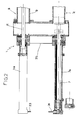
- 1 denotes in its entirety a pumping device comprising a container 2 suitable for containing a material to be pumped.
- the device 1 is particularly suitable for the pumping of concrete.
- the container 2, which is of the known type, has walls 3 and has at the top a wide opening for introduction of the concrete.
- the container 2 is sectioned along a horizontally sectioned plane.
- the device 1 comprises a first piston pump 4 with a horizontal-axis cylinder 5 terminating at one end in a first suction/delivery mouth 6 communicating with the inside of the container 2.
- 7 denotes the actuating stem of the piston sliding inside the cylinder 5.
- the device 1 also comprises a second piston pump 8 with a cylinder 9, the axis of which is parallel to that of the cylinder 5 and lying on the same horizontal plane.
- the cylinder 9 terminates in a second suction/delivery mouth 10 communicating with the inside of the container 2 and located alongside the first mouth 6, substantially coplanar with respect to the latter.
- 11 denotes the actuating stem of the piston sliding inside the cylinder 9.
- the two actuating stems 7 and 11 slide inside respective hydraulic cylinders 7a and 11a operated by the hydraulic circuit which will be described below.
- the piston pumps 4 and 8, during use, are designed to perform alternately, via the associated suction/delivery mouths 6 and 10, suction and compression of a part of the material contained in the container 2.
- the pumps 4 and 8 are operated by means of a hydraulic transmission circuit, as a result of which the pumps act in phase with one another so that, when one performs the compression phase, the other one performs the suction phase.
- the device 1 is provided with a deviating member 12 comprising a movable connection duct 13 provided with an inlet aperture 14 for the concrete pressed by the piston pumps 4 and 8.
- connection duct 13 is capable of rotating about an axis of rotation x-x, following operation by drive means, denoted in their entirety by 15, which act in synchronism with the action of the piston pumps 4 and 8.
- the connection duct 13 has the possibility of assuming selectively at least a first position and a second position in which the inlet aperture 14 is sealingly connected to the first suction/delivery mouth 6 and, respectively, to the second suction/delivery mouth 10.
- connection duct 13 has an outlet end 16 connected to a conveying duct 17 (illustrated only partly in Figure 1) for conveying the concrete, also at considerable distances and heights.
- the outlet end 16 and an entry mouth 18 of the conveying duct 17 are coaxial and directly facing one another; their common axis coincides with the axis of rotation x-x of the conveying duct 13, so that during rotation of the latter they remain coaxially facing and communicating.
- the end part 19 of the connection duct 13 is cylindrical with an axis x-x and is rotatably coupled to the container 2 by means of rolling support elements 20.
- the inlet aperture 14 of the duct 13 extends longitudinally between the first suction/delivery mouth 6 and the second suction/delivery mouth 10 and has the shape of a curved eyelet with its longitudinal axis substantially in the form of an arc of a circumference, the centre of which is situated in the vicinity of or coinciding with the axis of rotation x-x of the connection duct 13.
- the angular amplitude of the inlet aperture 14 is slightly less than 180°.
- sealing means of the known type, operating between the inlet aperture 14 and a fixed wear plate 21 which is mounted at one end of the piston pumps 4 and 8 and on which the connection duct 13 is designed to slide during use.
- the suction/delivery mouths 6 and 10 of the piston pumps 4 and 8 are situated in diametrically opposite positions with respect to the axis of rotation x-x of the connection duct 13.
- the drive means 15 are designed to cause continuous rotation of the connection duct 13. These drive means 15 are arranged outside the container 2 and do not come into contact with the concrete.
- connection duct 13 gradually narrows from the inlet aperture 14 towards the outlet end 16 leading into the conveying duct 17.
- the longitudinal axis of the connection duct 13 is a curved line substantially in the form of an "S", as shown in Figure 4.
- the drive means 15 comprise a hydraulic motor 22, with a reducer 23, having a predetermined swept volume equal to the displacement of the two pistons 7a and 11a.
- the motor 22 imparts the rotation to a pivot 26 on which the movable connection duct is keyed.
- the oil leaving the hydraulic motor 22, via a duct 27, enters into a rotating distributor 28 moved, by means of a chain 29, by the same pivot 26 on which a pinion 30 is keyed.
- the chain 29, actuated by the pinion 30, causes rotation of a pinion 31 keyed onto a shaft of the rotating distributor 28.
- the oil supplied from the motor enters into the rotating distributor through an inlet 32 and emerges alternately from the mouth 33 or 34, each of which supplies respectively the hydraulic cylinder 7a or 11a.
- the oil which, for example, enters into the chamber of the cylinder 7a compresses the oil which is located underneath the piston and is conveyed, via the connection 35, to the bottom chamber of the other cylinder lla which is thus moved in the opposite direction to the previous one, resulting in the alternating movement of the pistons.
- the pumping control system is therefore entirely hydraulic/mechanical.
- the device 1 operates as follows.
- the piston pumps 4 and 8 are activated so as to perform alternately the respective compression and suction strokes in phase with one another, while the connection duct 13 is operated so as to perform a continuous rotational movement about the axis x-x; this movement is synchronised with operation of the piston pumps 4 and 8.
- the inlet aperture 14 is positioned at least partially facing, in a sealing manner, the end mouth of one of the piston pumps, i.e. the pump performing the compression phase. In this way the concrete is able to pass, via the connection duct 13, from the pump to the conveying duct 17.
Abstract
Description
Claims (6)
- Pumping device (1) of the type comprising: a container (2), suitable for containing a material to be pumped; a first piston pump (4), having a suction/delivery mouth (6) communicating with the inside of the container (2); and a second piston pump (8), having a second suction/delivery mouth (10) also communicating with the inside of the container (2), the said piston pumps (4) and (8), during use, being designed to perform alternately, via the associated suction/delivery mouths (6) and (10), suction and compression of a part of the material contained in the container (2), characterized in that it comprises a deviating member (12), comprising a movable connection duct (13) provided with an aperture (14) for introduction of the material pressed by the said piston pumps (4) and (8), the connection duct (13) being capable of rotating continuously, following operation synchronised with that of said piston pumps (4) and (8), about an axis of rotation (x-x) with the possibility of assuming selectively at least a first position and a second position in which the inlet aperture (14) is sealingly connected to the first suction/delivery mouth (6) and, respectively, to the second suction/delivery mouth (10), it being envisaged that, in both the abovementioned positions of the connection duct (13), an outlet end (16) thereof is connected to a duct (17) for conveying the material, said inlet aperture (14) extending longitudinally between the first and the second suction/delivery mouths (6) and (10) and having its longitudinal axis substantially in the form of an arc of a circumference, the centre of which is situated in the vicinity of or coinciding with the axis of rotation (x-x) of the connection duct (13).
- Device according to Claim 1, characterized in that it comprises means (15) designed to cause continuous rotation of the connection duct (13).
- Device according to Claim 1 or 2, characterized in that the suction/delivery mouths (6) and (10) of the piston pumps (4) and (8) are situated in diametrically opposite positions with respect to the axis of rotation (x-x) of the connection duct (13).
- Device according to any one of the preceding claims, characterized in that the flow cross-section of the connection duct (13) narrows gradually from the inlet aperture (14) towards the said outlet end (16).
- Device according to any one of the preceding claims, characterized in that the said drive means (15) designed to cause rotation of the connection duct (13) are located outside the container (2).
- Device according to any one of the preceding claims, characterized in that the said drive means (15) comprise a hydraulic motor (22) which imparts the rotation to the connection duct (13) and to a rotating distributor (28) which is supplied with the discharge oil of the motor and transmits said oil alternately to the inlet of one of two hydraulic cylinders (7a) or (11a) which actuate respectively the piston pumps (4) and (11).
Applications Claiming Priority (2)
| Application Number | Priority Date | Filing Date | Title |
|---|---|---|---|
| IT97PR000002A IT1294068B1 (en) | 1997-01-17 | 1997-01-17 | PUMPING DEVICE, IN PARTICULAR FOR CEMENTITIOUS MATERIAL. |
| ITPR970002 | 1997-01-17 |
Publications (2)
| Publication Number | Publication Date |
|---|---|
| EP0854285A2 true EP0854285A2 (en) | 1998-07-22 |
| EP0854285A3 EP0854285A3 (en) | 1999-11-24 |
Family
ID=11396048
Family Applications (1)
| Application Number | Title | Priority Date | Filing Date |
|---|---|---|---|
| EP98830016A Withdrawn EP0854285A3 (en) | 1997-01-17 | 1998-01-16 | Pumping device, in particular for cement material |
Country Status (2)
| Country | Link |
|---|---|
| EP (1) | EP0854285A3 (en) |
| IT (1) | IT1294068B1 (en) |
Cited By (4)
| Publication number | Priority date | Publication date | Assignee | Title |
|---|---|---|---|---|
| WO2001042570A1 (en) * | 1999-12-08 | 2001-06-14 | Putzmeister Aktiengesellschaft | Method and arrangement for concreting vertical shafts |
| WO2005085636A1 (en) * | 2004-02-26 | 2005-09-15 | Schwing Gmbh | Thick matter piston pump |
| CN103352822A (en) * | 2013-06-20 | 2013-10-16 | 山东科技大学 | Plunger tilting tray type slush pump |
| EP4012181A1 (en) * | 2020-12-10 | 2022-06-15 | Liebherr-Mischtechnik GmbH | Delivery device for thick substance |
Citations (6)
| Publication number | Priority date | Publication date | Assignee | Title |
|---|---|---|---|---|
| US3068806A (en) * | 1961-07-10 | 1962-12-18 | Robert T Sherrod | Pump for semi-fluid material |
| US3663129A (en) * | 1970-09-18 | 1972-05-16 | Leon A Antosh | Concrete pump |
| US3829254A (en) * | 1971-10-26 | 1974-08-13 | E Pieper | Pump for concrete and the like |
| EP0422745A1 (en) * | 1989-10-13 | 1991-04-17 | Pieter Faber | Concrete-pumping device |
| EP0690229A1 (en) * | 1994-06-28 | 1996-01-03 | Sedepro | Positive displacement pump with a rotary valve |
| DE19503986A1 (en) * | 1995-02-07 | 1996-08-08 | Hudelmaier Ulrike | Method and device for conveying concrete or other thick materials |
-
1997
- 1997-01-17 IT IT97PR000002A patent/IT1294068B1/en active IP Right Grant
-
1998
- 1998-01-16 EP EP98830016A patent/EP0854285A3/en not_active Withdrawn
Patent Citations (6)
| Publication number | Priority date | Publication date | Assignee | Title |
|---|---|---|---|---|
| US3068806A (en) * | 1961-07-10 | 1962-12-18 | Robert T Sherrod | Pump for semi-fluid material |
| US3663129A (en) * | 1970-09-18 | 1972-05-16 | Leon A Antosh | Concrete pump |
| US3829254A (en) * | 1971-10-26 | 1974-08-13 | E Pieper | Pump for concrete and the like |
| EP0422745A1 (en) * | 1989-10-13 | 1991-04-17 | Pieter Faber | Concrete-pumping device |
| EP0690229A1 (en) * | 1994-06-28 | 1996-01-03 | Sedepro | Positive displacement pump with a rotary valve |
| DE19503986A1 (en) * | 1995-02-07 | 1996-08-08 | Hudelmaier Ulrike | Method and device for conveying concrete or other thick materials |
Cited By (7)
| Publication number | Priority date | Publication date | Assignee | Title |
|---|---|---|---|---|
| WO2001042570A1 (en) * | 1999-12-08 | 2001-06-14 | Putzmeister Aktiengesellschaft | Method and arrangement for concreting vertical shafts |
| US6776558B1 (en) * | 1999-12-08 | 2004-08-17 | Putzmeister Ag | Method and arrangement for concreting vertical shafts |
| WO2005085636A1 (en) * | 2004-02-26 | 2005-09-15 | Schwing Gmbh | Thick matter piston pump |
| KR100816029B1 (en) * | 2004-02-26 | 2008-03-21 | 슈빙 게엠베하 | Thick matter piston pump |
| CN100439703C (en) * | 2004-02-26 | 2008-12-03 | 施维英集团公司 | Thick matter piston pump |
| CN103352822A (en) * | 2013-06-20 | 2013-10-16 | 山东科技大学 | Plunger tilting tray type slush pump |
| EP4012181A1 (en) * | 2020-12-10 | 2022-06-15 | Liebherr-Mischtechnik GmbH | Delivery device for thick substance |
Also Published As
| Publication number | Publication date |
|---|---|
| ITPR970002A1 (en) | 1998-07-17 |
| EP0854285A3 (en) | 1999-11-24 |
| IT1294068B1 (en) | 1999-03-22 |
Similar Documents
| Publication | Publication Date | Title |
|---|---|---|
| US5458470A (en) | Pumping apparatus | |
| US5993181A (en) | Process and device for feeding concrete or other thick materials | |
| US6171075B1 (en) | Process and device for controlling a two-cylinder thick medium pump | |
| EP0422745A1 (en) | Concrete-pumping device | |
| CN1788159A (en) | Device and method for controlling a thick matter pump | |
| US6793467B2 (en) | Thick matter pump | |
| EP0854285A2 (en) | Pumping device, in particular for cement material | |
| US6450779B1 (en) | Two-cylinder thick matter pump | |
| JP4653096B2 (en) | Continuous flow reciprocating slurry pump | |
| CN107956666A (en) | A kind of two-cylinder type sludge pump with discharging sealing switching device | |
| US4893992A (en) | Two-cylinder thick-material pump | |
| JPH09506948A (en) | Slide valve device for 2-cylinder concentrated material pump | |
| EP0971127B1 (en) | Piston speed modulation for a concrete pump | |
| SU1016556A1 (en) | Concrete pump | |
| KR200434437Y1 (en) | Mortar pump | |
| JPH04506102A (en) | Fuel injection device for injection-type internal combustion engines | |
| KR102334498B1 (en) | high viscosity raw material valve | |
| JPS5819866B2 (en) | Swing sleeve valve used in 2-cylinder concrete pump | |
| JPH10205434A (en) | Slurry force fed device | |
| JPH04114197U (en) | lubricating oil supply pump | |
| JPH07253078A (en) | Valve device at carrying device of heavily viscous object | |
| CN1038491A (en) | The device of conveying flowable mediums | |
| KR19990016727U (en) | Swing valve driving device of piston pump for concrete pump car | |
| JPH0754627Y2 (en) | Forward / reverse switching device for concrete pump | |
| KR19980037449U (en) | Concrete suction discharge device of concrete pump truck |
Legal Events
| Date | Code | Title | Description |
|---|---|---|---|
| PUAI | Public reference made under article 153(3) epc to a published international application that has entered the european phase |
Free format text: ORIGINAL CODE: 0009012 |
|
| AK | Designated contracting states |
Kind code of ref document: A2 Designated state(s): AT BE CH DE DK ES FI FR GB GR IE IT LI LU MC NL PT SE |
|
| AX | Request for extension of the european patent |
Free format text: AL;LT;LV;MK;RO;SI |
|
| PUAL | Search report despatched |
Free format text: ORIGINAL CODE: 0009013 |
|
| AK | Designated contracting states |
Kind code of ref document: A3 Designated state(s): AT BE CH DE DK ES FI FR GB GR IE IT LI LU MC NL PT SE |
|
| AX | Request for extension of the european patent |
Free format text: AL;LT;LV;MK;RO;SI |
|
| AKX | Designation fees paid | ||
| REG | Reference to a national code |
Ref country code: DE Ref legal event code: 8566 |
|
| STAA | Information on the status of an ep patent application or granted ep patent |
Free format text: STATUS: THE APPLICATION IS DEEMED TO BE WITHDRAWN |
|
| 18D | Application deemed to be withdrawn |
Effective date: 20000525 |