EP0422745A1 - Concrete-pumping device - Google Patents
Concrete-pumping device Download PDFInfo
- Publication number
- EP0422745A1 EP0422745A1 EP90202724A EP90202724A EP0422745A1 EP 0422745 A1 EP0422745 A1 EP 0422745A1 EP 90202724 A EP90202724 A EP 90202724A EP 90202724 A EP90202724 A EP 90202724A EP 0422745 A1 EP0422745 A1 EP 0422745A1
- Authority
- EP
- European Patent Office
- Prior art keywords
- pump
- concrete
- hydraulic
- pressure
- frame
- Prior art date
- Legal status (The legal status is an assumption and is not a legal conclusion. Google has not performed a legal analysis and makes no representation as to the accuracy of the status listed.)
- Granted
Links
Images


Classifications
-
- F—MECHANICAL ENGINEERING; LIGHTING; HEATING; WEAPONS; BLASTING
- F04—POSITIVE - DISPLACEMENT MACHINES FOR LIQUIDS; PUMPS FOR LIQUIDS OR ELASTIC FLUIDS
- F04B—POSITIVE-DISPLACEMENT MACHINES FOR LIQUIDS; PUMPS
- F04B15/00—Pumps adapted to handle specific fluids, e.g. by selection of specific materials for pumps or pump parts
- F04B15/02—Pumps adapted to handle specific fluids, e.g. by selection of specific materials for pumps or pump parts the fluids being viscous or non-homogeneous
-
- F—MECHANICAL ENGINEERING; LIGHTING; HEATING; WEAPONS; BLASTING
- F04—POSITIVE - DISPLACEMENT MACHINES FOR LIQUIDS; PUMPS FOR LIQUIDS OR ELASTIC FLUIDS
- F04B—POSITIVE-DISPLACEMENT MACHINES FOR LIQUIDS; PUMPS
- F04B11/00—Equalisation of pulses, e.g. by use of air vessels; Counteracting cavitation
- F04B11/005—Equalisation of pulses, e.g. by use of air vessels; Counteracting cavitation using two or more pumping pistons
-
- F—MECHANICAL ENGINEERING; LIGHTING; HEATING; WEAPONS; BLASTING
- F04—POSITIVE - DISPLACEMENT MACHINES FOR LIQUIDS; PUMPS FOR LIQUIDS OR ELASTIC FLUIDS
- F04B—POSITIVE-DISPLACEMENT MACHINES FOR LIQUIDS; PUMPS
- F04B7/00—Piston machines or pumps characterised by having positively-driven valving
- F04B7/0019—Piston machines or pumps characterised by having positively-driven valving a common distribution member forming a single discharge distributor for a plurality of pumping chambers
- F04B7/0023—Piston machines or pumps characterised by having positively-driven valving a common distribution member forming a single discharge distributor for a plurality of pumping chambers and having a rotating movement
-
- F—MECHANICAL ENGINEERING; LIGHTING; HEATING; WEAPONS; BLASTING
- F04—POSITIVE - DISPLACEMENT MACHINES FOR LIQUIDS; PUMPS FOR LIQUIDS OR ELASTIC FLUIDS
- F04B—POSITIVE-DISPLACEMENT MACHINES FOR LIQUIDS; PUMPS
- F04B9/00—Piston machines or pumps characterised by the driving or driven means to or from their working members
- F04B9/08—Piston machines or pumps characterised by the driving or driven means to or from their working members the means being fluid
- F04B9/10—Piston machines or pumps characterised by the driving or driven means to or from their working members the means being fluid the fluid being liquid
- F04B9/109—Piston machines or pumps characterised by the driving or driven means to or from their working members the means being fluid the fluid being liquid having plural pumping chambers
- F04B9/117—Piston machines or pumps characterised by the driving or driven means to or from their working members the means being fluid the fluid being liquid having plural pumping chambers the pumping members not being mechanically connected to each other
- F04B9/1176—Piston machines or pumps characterised by the driving or driven means to or from their working members the means being fluid the fluid being liquid having plural pumping chambers the pumping members not being mechanically connected to each other the movement of each piston in one direction being obtained by a single-acting piston liquid motor
- F04B9/1178—Piston machines or pumps characterised by the driving or driven means to or from their working members the means being fluid the fluid being liquid having plural pumping chambers the pumping members not being mechanically connected to each other the movement of each piston in one direction being obtained by a single-acting piston liquid motor the movement in the other direction being obtained by a hydraulic connection between the liquid motor cylinders
-
- Y—GENERAL TAGGING OF NEW TECHNOLOGICAL DEVELOPMENTS; GENERAL TAGGING OF CROSS-SECTIONAL TECHNOLOGIES SPANNING OVER SEVERAL SECTIONS OF THE IPC; TECHNICAL SUBJECTS COVERED BY FORMER USPC CROSS-REFERENCE ART COLLECTIONS [XRACs] AND DIGESTS
- Y10—TECHNICAL SUBJECTS COVERED BY FORMER USPC
- Y10S—TECHNICAL SUBJECTS COVERED BY FORMER USPC CROSS-REFERENCE ART COLLECTIONS [XRACs] AND DIGESTS
- Y10S417/00—Pumps
- Y10S417/90—Slurry pumps, e.g. concrete
Definitions
- the invention relates to a concrete-pumping device compri literallysing a frame, a number of pump cylinders counted on the frame which comprise a pump opening close to one end, sealed plump pistons which are guided slidably in the pump cylinders toward and away from the pumping device and which are each coupled for reciprocal driving to the plunger of a coaxially arranged hydraulic jack, hydraulic switching means for cyclically feeding to and discharging from the jack hydraulic oil under pressure such that the plunger causes the reciprocating movement of the pump piston and concrete switching means for alternately placing the pump opening in communication with a feed funnel and a pressure conduit for concrete synchronously with the movement of the plump piston in order to pump concrete from the feed funnel into the pressure conduit.
- the invention therefore has for its object to provide a pumping device of the type mentioned in the preamble wherein this drawback does not occur.
- a concrete-pumping device comprises at least three pump cylinders with associated hydraulic jacks and the hydraulic and concrete switching means are embodied such that in each case before a pump cylinder has completed a pressure stroke another pump cylinder has already completed the suction stroke and the pump opening of this other pump cylinder is connected to the discharge line and that the pressure stroke of this pump opening of this other pump cylinder is connected to the discharge line and that the pressure stroke of this other pump cylinder immediately begins at the moment the pressure stroke of the one pump cylinder has been completed.
- the pressure strokes of the pump cylinders hereby follow one another without interruption, whereby a continuous, pulse-free flow occurs in the pressure conduit.
- a particularly favourable embodiment of the device according to the invention is characterised in claim 2 wherein the switching means are embodied reliably and operationally reliably despite the extra pump cylinder or cylinders.
- the step of claim 3 is preferably applied therein.
- the switching position of the hydraulic switching means and the concrete switching means is then determined by the rotation position of the rotatable unit so that synchronizing of these switching means is assured in a simple manner.
- the step of claim 4 is applied.
- the pump cylinders perform a complete pumping stroke ealch time irrespective of the operational conditions such as the composition of the concrete and the counter pressure experienced partly as a result thereof.
- the action of the plump cylinders can be reversed by rotating the slide valve part of the hydraulic switching means connected to the frame, that is, instead of pumping concrete out of the feed funnel to the pressure conduit, pumping it out of the pressure conduit back to the feed funnel.
- this blockage can practically always be cleared by switching the pumping device reciprocally. This can take place with the device according to this preferred embodiment in a simple manner by reciprocally rotating the rotatable slide valve part.
- the hydraulic jack of the pump cylinder which is already placed in communication with the pressure conduit while another pump cylinder is still occupied with the pressure stroke, can already be placed under hydraulic pressure.
- the pressure stroke will only begin when the pump cylinder already pressing has arrived at the end of its stroke because in order to set in motion the column of concrete received in the pump cylinder a greater force is needed than to maintain the movement of a concrete mass which is already in motion.
- automatically achieved is that the pressure stroke of the following pump cylinder in the cycle immediately begins at the moment the pressure stroke of the preceding pump cylinder in the cycle has been completed.
- the step of claim 6 can be applied.
- the angle through which the slide valve part connected to the frame is rotated reciprocally each time can be adjusted such that the moment of switching on of the pressure of the pressure stroke of the following pump cylinder is delayed until the moment that the pressure stroke of the preceding pump cylinder is practically wholly completed. Resulting from the accelerated setting into operation as a consequence of the reverse rotation of the slide valve part is a close succession of pressure strokes and therefore pulse-free transportation of concrete in the pressure conduit.
- a preferred embodiment which is distinguished by a simple and therefore operationally reliable construction is characterized in claim 7.
- the two hydraulic jacks of a pair can be controlled as a single hydraulic jack so that the hydraulic switching means can be considerably simplified.
- a simple and reliable embodiment of the concrete switching means is characterized in claim 8.
- the step of claim 9 is preferably applied therein.
- the outflow of the feed funnel can hereby be situated at a low level so that the feed funnel can be easily filled from a concrete mixing vehicle.
- the device according to the invention wherein the pump cylinders are combined into a rotating unit has the additional advantage that due to the rotation wear is distributed over the entire periphery of the cylinders so that the useful life of the pump cylinders is considerably increased.
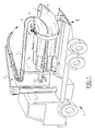
- the concrete-pumping device according to the invention shown in fig. 1 is embodied as a concrete-pumping truck.
- the actual concrete pump 2 is mounted between the chassis beams of the truck.
- the pump is provided with a feed funnel 3 into which concrete can be poured from a concrete mixer.
- the concrete is pressed byl the concrete pump 2 out of the feed funnel 3 into a pressure conduit 4.
- This pressure conduit 4 extends along a jib 5 so that concrete can be poured at distance and at height using a concrete-pumping vehicle 1.
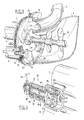
- each pump cylinder comprises a pump piston 10 which is connected to the plunger 11 of a hydraulic jack 14. Through suitable feed and discharge of hydraulic oil, as will be further described, the pump piston 10 can be moved reciprocally in the pump cylinder 6.
- the four pump cylinders 6-9 are assembled together with their associated hydraulic jacks into a unit mounted rotatably round a lengthwise shaft. This unit is rotatably mounted relative to the schematically indicated frame 16.
- the front ends of the pump cylinders 6-9 are fixedly welded for this purpose to a disc 20 such that the open ends of the pump cylinders 6-9 functioning as pump openings connect onto openings 26 in this disc 20.
- a rotary crown part 21 Along the edge of the disc 20 is arranged a rotary crown part 21.
- This rotary crown part 21 co-acts with a rotary crown part 22 arranged on a disc 29 fixedly connected to the frame.
- the disc 29 lies sealingly against the disc 20.
- kidney-shaped openings respectively a suction opening 28 on the underside and a pressure opening 27 on the upper part.
- a sealing 25 Arranged in the rotary crown part 21, 22 is a sealing 25 which prevents liquid leaking to the outside between the two discs 20, 29.
- a gear ring 23 Around the rotary crown part 21, 22 is mounted a gear ring 23. This gear ring 23 is in engagement with a pinion 24 which is driven by a hydrostatic motor 18 in a manner to be described later with reference to fig. 7.
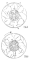
- Hydraulic switching means 35 which bring about the reciprocating stroke of the hydraulic jacks are arranged at the opposite end of the rotatable unit and are shown in more detail in fig. 7.
- the hydraulic switching means 35 comprise a slide valve part 36 which is fixedly connected to the rotating unit and therefore co-rotates therewith.
- a second slide valve part 37 is connected to the frame and comprises a non-rotatable housing 46 and an positioning slide 38 mounted rotatably therein.
- Arranged in the housing 46 are a feed port 39 for hydraulic oil under pressure and a discharge port 40 for hydraulic oil.
- the feed port 39 communicates with a core channel 41 of the positioning slide 38.
- the core channel debouches into a pressure recess 42 in a disc-like head 48 of the positioning slide 38.
- the discharge port 40 communicates with a casing channel 43 formed between the housing 46 and the slide 38 itself.
- This casing channel 43 communicates in turn with a suction recess 44 of the head disc.
- the rotating part 36 of the hydraulic switching means 35 comprises a disc 47 which lies against the head disc 48 and wherein are formed four connecting ports 45 which are connected by suitable lines to the hydraulic jacks in the manner made clear in fig. 7.
- the respective connecting ports 45 come to lie alternatingly in front of the pressure recess 42 and the suction recess 44.
- FIG. 7 shows, two pump cylinders with hydraulic jacks lying diametrically opposite one another are connected in each case to form oppositely moving pairs 6, 8 and 7, 9.
- the spaces behind the plungers are mutually connected as by a line 13 while the spaces in front of the plungers are connected by suitable lines, such as line 12, to connecting ports 45 situated diametrically opposite each other.
- the connecting port 45 lying diametrically opposite is situated in front of the suction recess 44 so that hydraulic oil under pressure can flow via the feed port 39, the core channel 41 and the pressure recess 42 to one of the hydraulic jacks of the relevant pair on the front side of the plunger thereof.
- Fig. 5 shows the position of the rotatable unit as shown in fig. 2.
- the pump cylinder 6 is rotated therein in the disc 29 just before the beginning of the kidney-shaped pressure opening 27 while the pump cylinder 7 is still situated just at the end of this pressure opening 27.
- Fig. 5 shows the position of the rotatable unit as shown in fig. 2.
- the pump cylinder 6 is rotated therein in the disc 29 just before the beginning of the kidney-shaped pressure opening 27 while the pump cylinder 7 is still situated just at the end of this pressure opening 27.
- the opening 45 associated with the pump cylinder 7 is still just in communication with the suction recess 44 while the opening 45 associated with the pump cylinder 9 is still just in communication with the pressure recess 42 of the hydraulic switching means 35.
- the pump cylinder 7 therefore carries out a pressure stroke while the pump cylinder 9 performs a suction stroke.
- all the hydraulic oil under pressure flows to the hydraulic jacks via the hydrostatic motor 18 which rotates the turning unit.
- This hydrostatic motor 18 is adjusted such that in the case of a complete revolution of the rotatable unit so much hydraulic oil has passed through the motor 18 that all the hydraulic jacks and therefore the pump cylinders have performed a complete reciprocating stroke and have thus returned to the starting position.
- each pump cylinder thus performs a pressure stroke as it passes along the pressure opening 27 and a suction stroke as it passes along the suction opening 28.
- the pump cylinder 7 is thus practically at the end of the pressure stroke while the pump cylinder 6 is located at the start of the pressure stroke.
- the pump cylinder 8 is likewise at the start of the suction stroke and the pump cylinder 9 at the end thereof.
- the hydraulic switching means 35 can be embodies such that the valve slide connected to the frame co-rotates each time with the rotatable unit through a small angle so that the mutual position of the openings 45 and the pressure and suction recesses remains unchanged roughly in the position as shown in fig. 6 until the relevant pump cylinder has fully completed the pressure stroke. At that moment the slide valve parts again move into their normal position whereby the pump cylinder ready for the pressure stroke is activated.
- a carrier construction which causes this path of movement can be embodied in many different ways such as, for example, with a curve-disc, a crank-drive rod mechanism or the like.
- the positioning slide 38 can perform the reciprocating rotation in a simple manner.
- the rotatable embodiment of the positioning slide 38 can be used for a rotation through 180 degrees.
- a lever 49 which can be operated manually or for example by an air cylinder.
- the pressure recess 42 and the suction recess 44 change places so that the cylinders which carry out a pressure stroke switch to a suction stroke and vice versa.
- This option is significant in eliminating blockages occurring in the pressure conduit 4 during operation.
- By turning the lever 49 back and forth pressure and suction occur alternately whereby a blockage can be rapidly eliminated.
- a stirring member 50 fixedly connected to the rotatable unit protrudes into the feed funnel 3. This ensures that the concrete in the feed funnel 3 remains well mixed.
Abstract
Description
- The invention relates to a concrete-pumping device comprising a frame, a number of pump cylinders counted on the frame which comprise a pump opening close to one end, sealed plump pistons which are guided slidably in the pump cylinders toward and away from the pumping device and which are each coupled for reciprocal driving to the plunger of a coaxially arranged hydraulic jack, hydraulic switching means for cyclically feeding to and discharging from the jack hydraulic oil under pressure such that the plunger causes the reciprocating movement of the pump piston and concrete switching means for alternately placing the pump opening in communication with a feed funnel and a pressure conduit for concrete synchronously with the movement of the plump piston in order to pump concrete from the feed funnel into the pressure conduit.
- With known concrete-pumping devices two pump cylinders operate alternately. The hydraulic switching means and the concrete switching means are reversed at the end of each stroke. During this reversing no concrete is pressed under pressure into the pressure conduit so that the pumping device operates pulsatingly. This pulsating operation is inconvenient particularly when the pressure conduit is arranged along a jib in order to be able to pour the concrete at a distance from the pumping device. Forces occurring due to the pulsatory action cause the jib to move up and down whereby the handling thereof is made difficult.
- The invention therefore has for its object to provide a pumping device of the type mentioned in the preamble wherein this drawback does not occur.
- With a concrete-pumping device according to the invention this is achieved in that this comprises at least three pump cylinders with associated hydraulic jacks and the hydraulic and concrete switching means are embodied such that in each case before a pump cylinder has completed a pressure stroke another pump cylinder has already completed the suction stroke and the pump opening of this other pump cylinder is connected to the discharge line and that the pressure stroke of this pump opening of this other pump cylinder is connected to the discharge line and that the pressure stroke of this other pump cylinder immediately begins at the moment the pressure stroke of the one pump cylinder has been completed. The pressure strokes of the pump cylinders hereby follow one another without interruption, whereby a continuous, pulse-free flow occurs in the pressure conduit.
- A particularly favourable embodiment of the device according to the invention is characterised in claim 2 wherein the switching means are embodied reliably and operationally reliably despite the extra pump cylinder or cylinders.
- The step of
claim 3 is preferably applied therein. The switching position of the hydraulic switching means and the concrete switching means is then determined by the rotation position of the rotatable unit so that synchronizing of these switching means is assured in a simple manner. - According to a further favourable development the step of
claim 4 is applied. Thus ensured is that the pump cylinders perform a complete pumping stroke ealch time irrespective of the operational conditions such as the composition of the concrete and the counter pressure experienced partly as a result thereof. - With the embodiment of the device as characterized in claim 5 the action of the plump cylinders can be reversed by rotating the slide valve part of the hydraulic switching means connected to the frame, that is, instead of pumping concrete out of the feed funnel to the pressure conduit, pumping it out of the pressure conduit back to the feed funnel. When a blockage occurs in the pressure conduit, something which can occur in practice, this blockage can practically always be cleared by switching the pumping device reciprocally. This can take place with the device according to this preferred embodiment in a simple manner by reciprocally rotating the rotatable slide valve part.
- In many circumstances the hydraulic jack of the pump cylinder, which is already placed in communication with the pressure conduit while another pump cylinder is still occupied with the pressure stroke, can already be placed under hydraulic pressure. The pressure stroke will only begin when the pump cylinder already pressing has arrived at the end of its stroke because in order to set in motion the column of concrete received in the pump cylinder a greater force is needed than to maintain the movement of a concrete mass which is already in motion. Hereby automatically achieved is that the pressure stroke of the following pump cylinder in the cycle immediately begins at the moment the pressure stroke of the preceding pump cylinder in the cycle has been completed.
- To be able also to effect this operation with certainty under difficult operational conditions, the step of
claim 6 can be applied. The angle through which the slide valve part connected to the frame is rotated reciprocally each time can be adjusted such that the moment of switching on of the pressure of the pressure stroke of the following pump cylinder is delayed until the moment that the pressure stroke of the preceding pump cylinder is practically wholly completed. Resulting from the accelerated setting into operation as a consequence of the reverse rotation of the slide valve part is a close succession of pressure strokes and therefore pulse-free transportation of concrete in the pressure conduit. - A preferred embodiment which is distinguished by a simple and therefore operationally reliable construction is characterized in
claim 7. The two hydraulic jacks of a pair can be controlled as a single hydraulic jack so that the hydraulic switching means can be considerably simplified. - A simple and reliable embodiment of the concrete switching means is characterized in
claim 8. - The step of
claim 9 is preferably applied therein. The outflow of the feed funnel can hereby be situated at a low level so that the feed funnel can be easily filled from a concrete mixing vehicle. - When a stirring member fixedly connected to the rotatable unit protrudes into the feed funnel it is achieved in a simple manner that the concrete in the feed funnel remains in a properly mixed state.
- With known concrete-pumping devices the lower part of the pump cylinders is considerably more subject to wear than the remaining part. The device according to the invention wherein the pump cylinders are combined into a rotating unit has the additional advantage that due to the rotation wear is distributed over the entire periphery of the cylinders so that the useful life of the pump cylinders is considerably increased.
- The invention will be further elucidated in the following description of an embodiment.
- Fig. 1 shows in perspective view of concrete-pumping device according to a preferred embodiment of the invention, constructed as a vehicle;
- fig. 2 shows a partly broken away perspective view of the actual concrete pump along the arrow II in fig. 1;
- fig. 3 shows a partly broken away perspective view along arrow III in fig. 2;
- fig. 4 shows a partly broken away perspective view along arrow IV in fig. 2;
- fig. 5 shows a partial section along line IV-IV in fig. 2;
- fig. 6 shows a section corresponding with fig. 5 in a somewhat rotated position of the device relative thereto;
- fig. 7 shows the hydraulic principle diagram of the driving of the concrete pump according to fig. 2.
- The concrete-pumping device according to the invention shown in fig. 1 is embodied as a concrete-pumping truck. The actual concrete pump 2 is mounted between the chassis beams of the truck. The pump is provided with a
feed funnel 3 into which concrete can be poured from a concrete mixer. The concrete is pressed byl the concrete pump 2 out of thefeed funnel 3 into apressure conduit 4. Thispressure conduit 4 extends along a jib 5 so that concrete can be poured at distance and at height using a concrete-pumping vehicle 1. - The actual concrete pump 2 is shown in more detail in fig. 2. According to the invention the concrete pump 2 comprises four
pump cylinders pump cylinder 6, each pump cylinder comprises apump piston 10 which is connected to theplunger 11 of ahydraulic jack 14. Through suitable feed and discharge of hydraulic oil, as will be further described, thepump piston 10 can be moved reciprocally in thepump cylinder 6. - The four pump cylinders 6-9 are assembled together with their associated hydraulic jacks into a unit mounted rotatably round a lengthwise shaft. This unit is rotatably mounted relative to the schematically indicated
frame 16. - As shown in fig. 3, the front ends of the pump cylinders 6-9 are fixedly welded for this purpose to a
disc 20 such that the open ends of the pump cylinders 6-9 functioning as pump openings connect onto openings 26 in thisdisc 20. Along the edge of thedisc 20 is arranged arotary crown part 21. Thisrotary crown part 21 co-acts with arotary crown part 22 arranged on adisc 29 fixedly connected to the frame. Thedisc 29 lies sealingly against thedisc 20. In thedisc 29 are arranged kidney-shaped openings, respectively a suction opening 28 on the underside and a pressure opening 27 on the upper part. Arranged in therotary crown part discs - Around the
rotary crown part gear ring 23. Thisgear ring 23 is in engagement with apinion 24 which is driven by ahydrostatic motor 18 in a manner to be described later with reference to fig. 7. - Hydraulic switching means 35 which bring about the reciprocating stroke of the hydraulic jacks are arranged at the opposite end of the rotatable unit and are shown in more detail in fig. 7. The hydraulic switching means 35 comprise a
slide valve part 36 which is fixedly connected to the rotating unit and therefore co-rotates therewith. A secondslide valve part 37 is connected to the frame and comprises anon-rotatable housing 46 and anpositioning slide 38 mounted rotatably therein. Arranged in thehousing 46 are a feed port 39 for hydraulic oil under pressure and adischarge port 40 for hydraulic oil. The feed port 39 communicates with a core channel 41 of thepositioning slide 38. The core channel debouches into a pressure recess 42 in a disc-like head 48 of thepositioning slide 38. Thedischarge port 40 communicates with acasing channel 43 formed between thehousing 46 and theslide 38 itself. Thiscasing channel 43 communicates in turn with asuction recess 44 of the head disc. Therotating part 36 of the hydraulic switching means 35 comprises adisc 47 which lies against thehead disc 48 and wherein are formed four connectingports 45 which are connected by suitable lines to the hydraulic jacks in the manner made clear in fig. 7. When the rotatable unit is rotated the respective connectingports 45 come to lie alternatingly in front of thepressure recess 42 and thesuction recess 44. As fig. 7 shows, two pump cylinders with hydraulic jacks lying diametrically opposite one another are connected in each case to form oppositely movingpairs line 13 while the spaces in front of the plungers are connected by suitable lines, such asline 12, to connectingports 45 situated diametrically opposite each other. When one connectingport 45 is situated in front of thepressure recess 42 the connectingport 45 lying diametrically opposite is situated in front of thesuction recess 44 so that hydraulic oil under pressure can flow via the feed port 39, the core channel 41 and thepressure recess 42 to one of the hydraulic jacks of the relevant pair on the front side of the plunger thereof. Through the pressure exerted on the plunger this is constrained rearward wherein hydraulic oil is displaced from the space behind the plunger via the connecting line to the space behind the other plunger of the pair. This is hereby forced forward wherein the hydraulic oil flows out of the space in front of the plunger via the line to therelevant port 45 and there flows back via the suction connection, thecasing channel 43 and thedischarge port 40. When the rotating unit is turned through 90 degrees the two other pump cylinder-jack units will be driven in the manner described and at a following rotation through 90 degrees the plump cylinder-jack units of the first pair will again be driven in the opposing direction. Fig. 5 and 6 show schematically the co-action of the concrete switching means described with reference to fig. 3 and the hydraulic switching means described with reference to fig. 4 and 7. Fig. 5 shows the position of the rotatable unit as shown in fig. 2. Thepump cylinder 6 is rotated therein in thedisc 29 just before the beginning of the kidney-shaped pressure opening 27 while thepump cylinder 7 is still situated just at the end of this pressure opening 27. Shown in fig. 5 and 6, in each case in the middle, is the associated position of the hydraulic switching means 35 wherein theopenings 45, in each case correspond with the pump cylinder standing in the same angular position. That is, theopening 45 standing in the same angular position as a particular pump cylinder is joined to the space in front of the plunger of the hydraulic jack associated with the relevant pump cylinder. Fig. 5 shows that theopening 45 associated with thepump cylinder 7 is still just in communication with thesuction recess 44 while theopening 45 associated with thepump cylinder 9 is still just in communication with thepressure recess 42 of the hydraulic switching means 35. Thepump cylinder 7 therefore carries out a pressure stroke while thepump cylinder 9 performs a suction stroke. As fig. 7 shows, all the hydraulic oil under pressure flows to the hydraulic jacks via thehydrostatic motor 18 which rotates the turning unit. Thishydrostatic motor 18 is adjusted such that in the case of a complete revolution of the rotatable unit so much hydraulic oil has passed through themotor 18 that all the hydraulic jacks and therefore the pump cylinders have performed a complete reciprocating stroke and have thus returned to the starting position. In the situation shown, each pump cylinder thus performs a pressure stroke as it passes along the pressure opening 27 and a suction stroke as it passes along thesuction opening 28. In fig. 5 thepump cylinder 7 is thus practically at the end of the pressure stroke while thepump cylinder 6 is located at the start of the pressure stroke. Thepump cylinder 8 is likewise at the start of the suction stroke and thepump cylinder 9 at the end thereof. During the movement between the suction opening and the pressure opening and vice versa, such as for thepump cylinders openings 45 are not in communication with either the suction recess or the pressure recess of the hydraulic switching means 35. In the position in fig. 5 the hydraulic jack of thepump cylinder 6 already comes under pressure before the pressure stroke of thecylinder 7 is wholly completed. The pressure is the same and dependent on the resistance in thepressure conduit 4. Since a greater pressure is necessary to set in motion the quantity of concrete present in thecylinder 6 than to maintain the movement of the quantity of concrete still remaining in thecylinder 7, the pump piston of thecylinder 6 re mains stationary until the pump piston of thecylinder 7 has reached the end position. At that moment the pressure stroke of the cylinder immediately begins. No pulse hereby occurs during the transition and the concrete continues to flow pulse-free through thepressure conduit 4. - In very particular circumstances, the example in the case of inconsistent composition of the concrete for pumping, it is possible that the pump cylinder in the position of
cylinder 6 in fig. 5 could already start with the pressure stroke while the pump cylinder in the position ofcylinder 7 in fig. 5 has not yet wholly completed its pressure stroke. In this case the hydraulic switching means 35 can be embodies such that the valve slide connected to the frame co-rotates each time with the rotatable unit through a small angle so that the mutual position of theopenings 45 and the pressure and suction recesses remains unchanged roughly in the position as shown in fig. 6 until the relevant pump cylinder has fully completed the pressure stroke. At that moment the slide valve parts again move into their normal position whereby the pump cylinder ready for the pressure stroke is activated. A carrier construction which causes this path of movement can be embodied in many different ways such as, for example, with a curve-disc, a crank-drive rod mechanism or the like. In the embodiment of the hydraulic switching means 35 as shown here thepositioning slide 38 can perform the reciprocating rotation in a simple manner. - Instead of being used for a periodic rotation through a small angle, the rotatable embodiment of the
positioning slide 38 can be used for a rotation through 180 degrees. Mounted for this purpose on thepositioning slide 38 is alever 49 which can be operated manually or for example by an air cylinder. On rotation through 180 degrees thepressure recess 42 and thesuction recess 44 change places so that the cylinders which carry out a pressure stroke switch to a suction stroke and vice versa. This means that concrete can be sucked out of thepressure conduit 4 and pressed into thefeed funnel 3. This option is significant in eliminating blockages occurring in thepressure conduit 4 during operation. By turning thelever 49 back and forth pressure and suction occur alternately whereby a blockage can be rapidly eliminated. - Although the concrete-pumping device described here comprises four pump cylinders it is also possible to achieve pulse-free transportation of concrete through the
pressure conduit 4 with three pump cylinders. To this end, it is only necessary according to the invention that each time before a pump cylinder has completed a pressure stroke another pump cylinder has already completed a suction stroke and the pump opening of this other pump cylinder be connected to the discharge line and that the pressure stroke of this other pump cylinder immediately begins at the moment that the pressure stroke of the one pump cylinder has been completed. As described, however, the application of four pump cylinders has the advantage that they can be connected as oppositely moving pairs whereby control of the movements can be embodied very simply. - As can be seen in fig. 3, a stirring
member 50 fixedly connected to the rotatable unit protrudes into thefeed funnel 3. This ensures that the concrete in thefeed funnel 3 remains well mixed.
Claims (10)
Applications Claiming Priority (2)
| Application Number | Priority Date | Filing Date | Title |
|---|---|---|---|
| NL8902546 | 1989-10-13 | ||
| NL8902546A NL8902546A (en) | 1989-10-13 | 1989-10-13 | CONCRETE PUMPING EQUIPMENT. |
Publications (2)
| Publication Number | Publication Date |
|---|---|
| EP0422745A1 true EP0422745A1 (en) | 1991-04-17 |
| EP0422745B1 EP0422745B1 (en) | 1995-04-05 |
Family
ID=19855454
Family Applications (1)
| Application Number | Title | Priority Date | Filing Date |
|---|---|---|---|
| EP90202724A Expired - Lifetime EP0422745B1 (en) | 1989-10-13 | 1990-10-11 | Concrete-pumping device |
Country Status (6)
| Country | Link |
|---|---|
| US (1) | US5114319A (en) |
| EP (1) | EP0422745B1 (en) |
| JP (1) | JPH03185276A (en) |
| AT (1) | ATE120833T1 (en) |
| DE (1) | DE69018363T2 (en) |
| NL (1) | NL8902546A (en) |
Cited By (10)
| Publication number | Priority date | Publication date | Assignee | Title |
|---|---|---|---|---|
| AT403219B (en) * | 1995-02-01 | 1997-12-29 | Scheidl Rudolf Dipl Ing Dr Tec | DEVICE FOR DRIVING A HYDROSTATIC DRIVE |
| EP0854285A2 (en) * | 1997-01-17 | 1998-07-22 | Gian Guido Ravellini | Pumping device, in particular for cement material |
| US6081983A (en) * | 1998-05-15 | 2000-07-04 | Apex Tool And Manufacturing, Inc. | Screw element extractor |
| WO2005085636A1 (en) * | 2004-02-26 | 2005-09-15 | Schwing Gmbh | Thick matter piston pump |
| CN102220970A (en) * | 2011-07-14 | 2011-10-19 | 长春工业大学 | Blockage-preventing pump structure for concrete pump |
| CN103047508A (en) * | 2012-12-25 | 2013-04-17 | 三一重工股份有限公司 | Material conveying system and pipeline switching device thereof |
| CN103775300A (en) * | 2014-02-20 | 2014-05-07 | 中联重科股份有限公司 | Pumping device |
| CN104389851A (en) * | 2014-11-20 | 2015-03-04 | 徐州徐工施维英机械有限公司 | Hydraulic limiting device and concrete pump truck |
| CN105626606A (en) * | 2014-10-27 | 2016-06-01 | 中联重科股份有限公司 | Hydraulic system of concrete pumping equipment and concrete pumping equipment |
| CN109594780A (en) * | 2018-12-10 | 2019-04-09 | 佛山科学技术学院 | Mixed mud pumping installations |
Families Citing this family (17)
| Publication number | Priority date | Publication date | Assignee | Title |
|---|---|---|---|---|
| DE19804863A1 (en) * | 1998-02-09 | 1999-08-12 | Putzmeister Ag | Slide device for a two-cylinder slurry pump |
| AU2002950421A0 (en) * | 2002-07-29 | 2002-09-12 | Combined Resource Engineering Pty Ltd | Fluid operating pump |
| NL1034431C2 (en) * | 2007-09-27 | 2009-03-30 | Staring Beheer B V M | Slurry pump. |
| US20090220358A1 (en) * | 2008-02-29 | 2009-09-03 | Putzmeister America, Inc. | Unequal length alternating hydraulic cylinder drive system for continuous material output flow with equal material output pressure |
| US20090252626A1 (en) * | 2008-04-08 | 2009-10-08 | Andre Salvaire | Rotary Distributor for Pressure Multiplier |
| JP5105202B2 (en) * | 2008-06-23 | 2012-12-26 | 満男 大見 | Fluid conveying device |
| JP4924911B2 (en) * | 2009-11-18 | 2012-04-25 | 満男 大見 | Fluid pressure feeder |
| WO2012088850A1 (en) * | 2010-12-29 | 2012-07-05 | 湖南三一智能控制设备有限公司 | Material delivery system and switch device for delivery pipe thereof |
| WO2015167615A1 (en) * | 2014-04-27 | 2015-11-05 | National Oilwell Varco, L.P. | Multi-cylinder hydraulically-driven pump system |
| US10197047B2 (en) * | 2014-06-11 | 2019-02-05 | Graco Minnesota, Inc. | Hydraulic proportioning system with flow divider |
| USD788883S1 (en) | 2015-04-16 | 2017-06-06 | Robert A Drake | Pressure relief valve for use with concrete pumping system |
| US9732739B2 (en) | 2015-04-16 | 2017-08-15 | Robert A Drake | Concrete pumping system having safety recirculation and method features |
| CN106968908B (en) * | 2017-03-29 | 2020-06-30 | 长乐智睿恒创节能科技有限责任公司 | Stable conveying concrete pump and control method |
| US11143173B2 (en) | 2018-01-20 | 2021-10-12 | William E. Howseman, Jr. | Hydraulically synchronized pumps where the hydraulic motor of the master pump hydraulically drives the hydraulic motor of the slave pump |
| CN109113762B (en) * | 2018-07-24 | 2019-09-24 | 山东科技大学 | A kind of no pulse wet-spraying machine |
| CN109113763B (en) * | 2018-07-24 | 2019-09-24 | 山东科技大学 | No pulse wet-spraying machine |
| CN113775178B (en) * | 2021-09-10 | 2022-09-20 | 马国林 | Concrete pouring and conveying process |
Citations (5)
| Publication number | Priority date | Publication date | Assignee | Title |
|---|---|---|---|---|
| US3295451A (en) * | 1965-11-10 | 1967-01-03 | James E Smith | Hydraulic power converter |
| US3663129A (en) * | 1970-09-18 | 1972-05-16 | Leon A Antosh | Concrete pump |
| FR2163145A5 (en) * | 1971-11-29 | 1973-07-20 | Boyle Bede Alfred | |
| DE3219882A1 (en) * | 1982-05-27 | 1983-12-01 | Maschinenfabrik Walter Scheele GmbH & Co KG, 4750 Unna-Massen | Concrete pump |
| EP0249175A2 (en) * | 1986-06-13 | 1987-12-16 | Ab Asea-Atom | Pump means |
Family Cites Families (11)
| Publication number | Priority date | Publication date | Assignee | Title |
|---|---|---|---|---|
| US3262395A (en) * | 1963-06-10 | 1966-07-26 | Jorge A Morando | Hydraulic transformer |
| US3279383A (en) * | 1965-01-06 | 1966-10-18 | Burnup And Sims Inc | Hydraulic powered mobile concrete pump assembly |
| US3367272A (en) * | 1967-01-03 | 1968-02-06 | James E. Smith | Hydraulic power converter |
| DE1703219B2 (en) * | 1968-04-19 | 1977-02-24 | Putzmeister GmbH, Chur (Schweiz) | CONCRETE PUMP |
| US3650638A (en) * | 1969-12-19 | 1972-03-21 | Halliburton Co | Hydraulically powered pump having a precompression function |
| US4105373A (en) * | 1974-11-12 | 1978-08-08 | Fogt Industriemaschinenvertretung A.G. | Fluid distributor device for controlling an apparatus for pumping wet concrete and the like |
| US3981622A (en) * | 1974-11-20 | 1976-09-21 | Kelsey-Hayes Company | Hydraulic intensifier control system |
| WO1983001983A1 (en) * | 1981-11-25 | 1983-06-09 | Box, Frederick, James | Pump systems |
| DE3219982A1 (en) * | 1982-05-27 | 1983-12-01 | Daimler-Benz Ag, 7000 Stuttgart | Closing device for a flap or a lid on a motor vehicle |
| US4470771A (en) * | 1982-08-20 | 1984-09-11 | Towler Hydraulics, Inc. | Quadraplex fluid pump |
| GB8515944D0 (en) * | 1985-06-24 | 1985-07-24 | Normalair Garrett Ltd | Pressure intensifier device |
-
1989
- 1989-10-13 NL NL8902546A patent/NL8902546A/en not_active Application Discontinuation
-
1990
- 1990-10-10 US US07/595,242 patent/US5114319A/en not_active Expired - Fee Related
- 1990-10-11 DE DE69018363T patent/DE69018363T2/en not_active Expired - Fee Related
- 1990-10-11 AT AT90202724T patent/ATE120833T1/en not_active IP Right Cessation
- 1990-10-11 EP EP90202724A patent/EP0422745B1/en not_active Expired - Lifetime
- 1990-10-12 JP JP2275135A patent/JPH03185276A/en active Pending
Patent Citations (5)
| Publication number | Priority date | Publication date | Assignee | Title |
|---|---|---|---|---|
| US3295451A (en) * | 1965-11-10 | 1967-01-03 | James E Smith | Hydraulic power converter |
| US3663129A (en) * | 1970-09-18 | 1972-05-16 | Leon A Antosh | Concrete pump |
| FR2163145A5 (en) * | 1971-11-29 | 1973-07-20 | Boyle Bede Alfred | |
| DE3219882A1 (en) * | 1982-05-27 | 1983-12-01 | Maschinenfabrik Walter Scheele GmbH & Co KG, 4750 Unna-Massen | Concrete pump |
| EP0249175A2 (en) * | 1986-06-13 | 1987-12-16 | Ab Asea-Atom | Pump means |
Non-Patent Citations (1)
| Title |
|---|
| SOVIET INVENTIONS ILLUSTRATED,section Q,week 8515,22 mei 1985,class Q56,no 85-092080/15, SU-A-1116-209(SOYUZSPETSFUNDAMENT)22-06-1983 * |
Cited By (16)
| Publication number | Priority date | Publication date | Assignee | Title |
|---|---|---|---|---|
| AT403219B (en) * | 1995-02-01 | 1997-12-29 | Scheidl Rudolf Dipl Ing Dr Tec | DEVICE FOR DRIVING A HYDROSTATIC DRIVE |
| EP0854285A2 (en) * | 1997-01-17 | 1998-07-22 | Gian Guido Ravellini | Pumping device, in particular for cement material |
| EP0854285A3 (en) * | 1997-01-17 | 1999-11-24 | Gian Guido Ravellini | Pumping device, in particular for cement material |
| US6081983A (en) * | 1998-05-15 | 2000-07-04 | Apex Tool And Manufacturing, Inc. | Screw element extractor |
| WO2005085636A1 (en) * | 2004-02-26 | 2005-09-15 | Schwing Gmbh | Thick matter piston pump |
| KR100816029B1 (en) * | 2004-02-26 | 2008-03-21 | 슈빙 게엠베하 | Thick matter piston pump |
| CN100439703C (en) * | 2004-02-26 | 2008-12-03 | 施维英集团公司 | Thick matter piston pump |
| CN102220970B (en) * | 2011-07-14 | 2015-02-11 | 长春工业大学 | Blockage-preventing pump structure for concrete pump |
| CN102220970A (en) * | 2011-07-14 | 2011-10-19 | 长春工业大学 | Blockage-preventing pump structure for concrete pump |
| CN103047508A (en) * | 2012-12-25 | 2013-04-17 | 三一重工股份有限公司 | Material conveying system and pipeline switching device thereof |
| CN103047508B (en) * | 2012-12-25 | 2015-04-22 | 三一汽车制造有限公司 | Material conveying system and pipeline switching device thereof |
| CN103775300A (en) * | 2014-02-20 | 2014-05-07 | 中联重科股份有限公司 | Pumping device |
| CN103775300B (en) * | 2014-02-20 | 2016-08-17 | 中联重科股份有限公司 | Pumping equipment |
| CN105626606A (en) * | 2014-10-27 | 2016-06-01 | 中联重科股份有限公司 | Hydraulic system of concrete pumping equipment and concrete pumping equipment |
| CN104389851A (en) * | 2014-11-20 | 2015-03-04 | 徐州徐工施维英机械有限公司 | Hydraulic limiting device and concrete pump truck |
| CN109594780A (en) * | 2018-12-10 | 2019-04-09 | 佛山科学技术学院 | Mixed mud pumping installations |
Also Published As
| Publication number | Publication date |
|---|---|
| DE69018363D1 (en) | 1995-05-11 |
| DE69018363T2 (en) | 1995-07-27 |
| JPH03185276A (en) | 1991-08-13 |
| EP0422745B1 (en) | 1995-04-05 |
| US5114319A (en) | 1992-05-19 |
| NL8902546A (en) | 1991-05-01 |
| ATE120833T1 (en) | 1995-04-15 |
Similar Documents
| Publication | Publication Date | Title |
|---|---|---|
| EP0422745A1 (en) | Concrete-pumping device | |
| US5993181A (en) | Process and device for feeding concrete or other thick materials | |
| EP0197632B1 (en) | Actuator for a reciprocating slurry pump | |
| US6171075B1 (en) | Process and device for controlling a two-cylinder thick medium pump | |
| EP0251076B1 (en) | Vibrating plate compactor | |
| US3667869A (en) | Dual cylinder-concrete pump | |
| US3939656A (en) | Hydrostatic transmission pump | |
| EP0492928A1 (en) | Method and apparatus for fluid flow control | |
| US6793467B2 (en) | Thick matter pump | |
| US4385869A (en) | Reciprocation pump | |
| JP4653096B2 (en) | Continuous flow reciprocating slurry pump | |
| US3771421A (en) | Thrust piston motors | |
| US4621747A (en) | Apparatus for charge-wise dosing a metered volume quantity of a flowing medium continuously supplied to the apparatus under delivery pressure | |
| US5671873A (en) | Proportioning apparatus for viscous materials | |
| US3749525A (en) | Hydraulically operated fluid aggregate pump | |
| US4569642A (en) | Slurry pump | |
| US3807706A (en) | Concrete handling arrangement | |
| JPS6214715B2 (en) | ||
| US4893992A (en) | Two-cylinder thick-material pump | |
| RU2000124311A (en) | PRESS WITH EXCENTRIC CRANIAL DRIVE OF UPPER PUNCH BLOCK AND METHOD OF ITS OPERATION | |
| CN210186898U (en) | Liquid dispensing pump and liquid dispensing device | |
| US2608183A (en) | Hydraulic oscillator for the shaft of an agitator | |
| GB1335194A (en) | Apparatus operating on the positive displacement principle and usable as a fluid pump or as a motor | |
| EP0854285A2 (en) | Pumping device, in particular for cement material | |
| JPH01309797A (en) | Slide driving device for press |
Legal Events
| Date | Code | Title | Description |
|---|---|---|---|
| PUAI | Public reference made under article 153(3) epc to a published international application that has entered the european phase |
Free format text: ORIGINAL CODE: 0009012 |
|
| AK | Designated contracting states |
Kind code of ref document: A1 Designated state(s): AT BE CH DE DK ES FR GB GR IT LI LU NL SE |
|
| 17P | Request for examination filed |
Effective date: 19911011 |
|
| 17Q | First examination report despatched |
Effective date: 19930303 |
|
| ITF | It: translation for a ep patent filed |
Owner name: STUDIO INGG. FISCHETTI & WEBER |
|
| GRAA | (expected) grant |
Free format text: ORIGINAL CODE: 0009210 |
|
| AK | Designated contracting states |
Kind code of ref document: B1 Designated state(s): AT BE CH DE DK ES FR GB GR IT LI LU NL SE |
|
| PG25 | Lapsed in a contracting state [announced via postgrant information from national office to epo] |
Ref country code: LI Effective date: 19950405 Ref country code: GR Free format text: LAPSE BECAUSE OF FAILURE TO SUBMIT A TRANSLATION OF THE DESCRIPTION OR TO PAY THE FEE WITHIN THE PRESCRIBED TIME-LIMIT Effective date: 19950405 Ref country code: ES Free format text: THE PATENT HAS BEEN ANNULLED BY A DECISION OF A NATIONAL AUTHORITY Effective date: 19950405 Ref country code: DK Effective date: 19950405 Ref country code: CH Effective date: 19950405 Ref country code: BE Effective date: 19950405 Ref country code: AT Effective date: 19950405 |
|
| REF | Corresponds to: |
Ref document number: 120833 Country of ref document: AT Date of ref document: 19950415 Kind code of ref document: T |
|
| REF | Corresponds to: |
Ref document number: 69018363 Country of ref document: DE Date of ref document: 19950511 |
|
| ET | Fr: translation filed | ||
| PG25 | Lapsed in a contracting state [announced via postgrant information from national office to epo] |
Ref country code: SE Effective date: 19950705 |
|
| REG | Reference to a national code |
Ref country code: CH Ref legal event code: PL |
|
| PG25 | Lapsed in a contracting state [announced via postgrant information from national office to epo] |
Ref country code: LU Free format text: LAPSE BECAUSE OF NON-PAYMENT OF DUE FEES Effective date: 19951031 |
|
| PLBE | No opposition filed within time limit |
Free format text: ORIGINAL CODE: 0009261 |
|
| STAA | Information on the status of an ep patent application or granted ep patent |
Free format text: STATUS: NO OPPOSITION FILED WITHIN TIME LIMIT |
|
| 26N | No opposition filed | ||
| PGFP | Annual fee paid to national office [announced via postgrant information from national office to epo] |
Ref country code: FR Payment date: 19991228 Year of fee payment: 10 |
|
| PGFP | Annual fee paid to national office [announced via postgrant information from national office to epo] |
Ref country code: GB Payment date: 20000128 Year of fee payment: 10 |
|
| PG25 | Lapsed in a contracting state [announced via postgrant information from national office to epo] |
Ref country code: GB Free format text: LAPSE BECAUSE OF NON-PAYMENT OF DUE FEES Effective date: 20001011 |
|
| GBPC | Gb: european patent ceased through non-payment of renewal fee |
Effective date: 20001011 |
|
| PG25 | Lapsed in a contracting state [announced via postgrant information from national office to epo] |
Ref country code: FR Free format text: LAPSE BECAUSE OF NON-PAYMENT OF DUE FEES Effective date: 20010629 |
|
| REG | Reference to a national code |
Ref country code: FR Ref legal event code: ST |
|
| PG25 | Lapsed in a contracting state [announced via postgrant information from national office to epo] |
Ref country code: IT Free format text: LAPSE BECAUSE OF NON-PAYMENT OF DUE FEES;WARNING: LAPSES OF ITALIAN PATENTS WITH EFFECTIVE DATE BEFORE 2007 MAY HAVE OCCURRED AT ANY TIME BEFORE 2007. THE CORRECT EFFECTIVE DATE MAY BE DIFFERENT FROM THE ONE RECORDED. Effective date: 20051011 |
|
| PGFP | Annual fee paid to national office [announced via postgrant information from national office to epo] |
Ref country code: NL Payment date: 20070430 Year of fee payment: 17 Ref country code: DE Payment date: 20070430 Year of fee payment: 17 |
|
| NLV4 | Nl: lapsed or anulled due to non-payment of the annual fee |
Effective date: 20080501 |
|
| PG25 | Lapsed in a contracting state [announced via postgrant information from national office to epo] |
Ref country code: DE Free format text: LAPSE BECAUSE OF NON-PAYMENT OF DUE FEES Effective date: 20080501 |
|
| PG25 | Lapsed in a contracting state [announced via postgrant information from national office to epo] |
Ref country code: NL Free format text: LAPSE BECAUSE OF NON-PAYMENT OF DUE FEES Effective date: 20080501 |