EP0854274A1 - Particulate filter - Google Patents
Particulate filter Download PDFInfo
- Publication number
- EP0854274A1 EP0854274A1 EP97121164A EP97121164A EP0854274A1 EP 0854274 A1 EP0854274 A1 EP 0854274A1 EP 97121164 A EP97121164 A EP 97121164A EP 97121164 A EP97121164 A EP 97121164A EP 0854274 A1 EP0854274 A1 EP 0854274A1
- Authority
- EP
- European Patent Office
- Prior art keywords
- filter
- particle filter
- flow
- resistance
- flow resistance
- Prior art date
- Legal status (The legal status is an assumption and is not a legal conclusion. Google has not performed a legal analysis and makes no representation as to the accuracy of the status listed.)
- Granted
Links
Images
Classifications
-
- F—MECHANICAL ENGINEERING; LIGHTING; HEATING; WEAPONS; BLASTING
- F01—MACHINES OR ENGINES IN GENERAL; ENGINE PLANTS IN GENERAL; STEAM ENGINES
- F01N—GAS-FLOW SILENCERS OR EXHAUST APPARATUS FOR MACHINES OR ENGINES IN GENERAL; GAS-FLOW SILENCERS OR EXHAUST APPARATUS FOR INTERNAL COMBUSTION ENGINES
- F01N3/00—Exhaust or silencing apparatus having means for purifying, rendering innocuous, or otherwise treating exhaust
- F01N3/02—Exhaust or silencing apparatus having means for purifying, rendering innocuous, or otherwise treating exhaust for cooling, or for removing solid constituents of, exhaust
- F01N3/021—Exhaust or silencing apparatus having means for purifying, rendering innocuous, or otherwise treating exhaust for cooling, or for removing solid constituents of, exhaust by means of filters
- F01N3/023—Exhaust or silencing apparatus having means for purifying, rendering innocuous, or otherwise treating exhaust for cooling, or for removing solid constituents of, exhaust by means of filters using means for regenerating the filters, e.g. by burning trapped particles
Definitions
- the invention relates to a particle filter in the exhaust gas flow of a diesel engine is arranged and a method for complete Regenerate it.
- Particle filters are used to separate soot particles from the exhaust gas of diesel engines. With increasing thickness of the particle coating the exhaust gas pressure in front of the particle filter increases. Is a certain one Pressure level is reached, the particle filter is burned off regenerates the particle coating. This usually happens by exhaust gas of certain pressure and temperature, that from the diesel engine and one in the main stream of the Exhaust pipe arranged burner is supplied.
- the invention has for its object to provide a particle filter the particle coating completely burned off with each regeneration becomes.
- ⁇ o is meaningless and generally. also not measurable, since even a very low initial load can significantly increase the filter resistance.
- the pressure loss ⁇ o in the pure state of a filter medium or a filter constructed with it can therefore only be determined when the filter flows through with particle-free measuring gas.
- a partially regenerated particle filter leads to a shortening of the Loading phase and thereby to an undesirable increase the regeneration cycles and the possible overloading of the not completely regenerated filter surfaces with the risk of destruction in one of the following regenerations.
- the particle filter depending of operating parameters by burning off the soot particles is regenerable, complete regeneration is achieved by that the load-independent flow resistance of a Filter unit over its entire flow cross-section at least 5% of the flow resistance of the loaded particle filter at its regeneration threshold.
- This in the entire particle filter effective load-independent flow resistance that during the regeneration also the last remaining ones Areas covered with particles of particulate matter flow through the exhaust gas and burned free will.
- the bypass flow becomes too strong through the first regenerated areas of the particle filter and the associated drop in pressure of the regeneration gas avoided.
- the location of the first regenerated area is irrelevant Role because the load-independent flow resistance of the entire Particle filter is raised.
- the required level of flow resistance independent of the load the particle filter e.g. up to 10% of the flow resistance can be at the regeneration threshold a compromise between low fuel consumption of the diesel engine and safe regeneration of the particle filter.
- measures to increase the level of the load-independent flow resistance is described. If solid walls made of porous, heat-resistant Material is provided is their flow resistance by their wall thickness, porosity and degree of surface sealing influenceable. When wound or knitted as a filter medium Structures made of heat-resistant fibers on a carrier body are arranged, the flow resistance through the thickness and density of the structures and / or by wall thickness, porosity and Degree of surface sealing of the carrier body can be influenced.
- An advantageous development of the invention is that at a stationary regeneration device for easy-change filters of the resistance bodies arranged in the stationary regeneration device and therefore only once for any number of spin-on filters is required.
- Flow channels of the resistance body have laminar flows. It can be achieved that the desired influence the flow distribution in the filter, which itself is also predominant flow is laminar, largely independent of the size of the other influencing parameters, such as mass flow, temperature, viscosity, remains. Even in the case of regeneration processes with very little Gas flow rate, e.g. "Secondary flow regeneration" is the desired one Effect achievable without causing an undesirably large pressure increase comes in the loading operation.
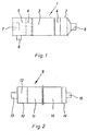
- Figure 1 shows a filter unit 1 with a filter housing 2, in which a particle filter 3 with a downstream or upstream resistance body 4 are arranged.
- a particle filter 3 with a downstream or upstream resistance body 4 In the anteroom 5 with an exhaust gas inlet 6 for the exhaust gas of the diesel engine is a burner 7 for heating provided the same. The cleaned exhaust gas leaves the filter housing 2 through an exhaust outlet 8.
- the particle filter 3 is a wound filter with filter cartridges or - preferably - designed as a honeycomb filter.
- the particle filter has a load-independent flow resistance from 5% to 10% of the flow resistance at the regeneration threshold on, creating a gas pressure required for regeneration is ensured during the entire regeneration.
- the resistance bodies 4 are arranged immediately after or in front of the particle filter 3. This ensures an even flow distribution across the cross-section of the particle filter 3 ensured.
- the flow resistance of the Resistor body 4 can correspond to the respective installation conditions to get voted.
- FIG. 2 shows a stationary regeneration device 9.
- a stationary resistance body 11 and a prechamber 12 are arranged, into which a regeneration gas generator 13 opens. This essentially exists from an air blower and an electric heater.
- a replaceable filter housing 14 is located on the stationary regeneration device 9 attachable with an outlet 15.
- the easy-change filter housing 14 is a Easy-change filter 16 arranged.
- the flow resistance of the stationary Resistor body 11 is in the range of the flow resistance of the loaded spin-on filter 16. This results in a very even loading of the easy-change filter 16 with regeneration gas and thus a quick one and enables thorough regeneration.
- the particle filter 3 or the resistance body 4, 11 becomes one complete regeneration and thus the original loading time reached, because the pressure of the regeneration gas due to the increased load independent Flow resistance until complete regeneration of the particle filter has the required height. To this Way is an increase in the life of the particle filter without noticeable Increased fuel consumption of the diesel engine realized.
Abstract
Description
Die Erfindung betrifft ein Partikelfilter, das im Abgasstrom einer Dieselbrennkraftmaschine angeordnet ist und ein Verfahren zum vollständigen Regenerieren desselben.The invention relates to a particle filter in the exhaust gas flow of a diesel engine is arranged and a method for complete Regenerate it.
Partikelfilter dienen zum Abscheiden von Rußpartikeln aus dem Abgas von Dieselbrennkraftmaschinen. Mit wachsender Dicke des Partikelbelags steigt der Abgasdruck vor dem Partikelfilter an. Ist ein bestimmtes Druckniveau erreicht, wird das Partikelfilter durch Abbrennen des Partikelbelags regeneriert. Dies geschieht üblicherweise durch Abgas von bestimmtem Druck und bestimmter Temperatur, das von der Dieselbrennkraftmaschine und von einem im Hauptstrom der Abgasleitung angeordneten Brenner geliefert wird.Particle filters are used to separate soot particles from the exhaust gas of diesel engines. With increasing thickness of the particle coating the exhaust gas pressure in front of the particle filter increases. Is a certain one Pressure level is reached, the particle filter is burned off regenerates the particle coating. This usually happens by exhaust gas of certain pressure and temperature, that from the diesel engine and one in the main stream of the Exhaust pipe arranged burner is supplied.
In der EP- 0 507 116 B1 wird für ein Partikelfilter mit Filterkerzen, die aus einem mit Filtermaterial belegten Tragrohr bestehen, vorgeschlagen, den beladungsunabhängigen Strömungswiderstand der Filterkerzen über deren Länge unterschiedlich zu gestalten. Als Mittel dazu dient eine unterschiedliche Dicke des Filtermaterials, die durch konische Tragrohre bei zylindrischer Außenform der Filterkerzen verwirklicht wird. Die größere Dicke des Filtermaterials ist den bei der Regeneration bevorzugten Partien der Filterkerzen zugeordnet, während die benachteiligten Partien einen geringeren Strömungswiderstand durch entsprechend geringere Dicke des Filtermaterials aufweisen, wodurch die Durchströmung mit heißen Regenerationsgas gefördert wird. Diese Lösung setzt voraus, daß die Regeneration immer in der geplanten Weise abläuft. Der komplexen Form des Temperatur- und Strömungsfelds in einem solchen Partikelfilter kann aber der vorliegenden Verteilung des Strömungswiderstands über die Oberfläche der Filterkerzen nicht gerecht werden. So wird es auch bei dieser Lösung bevorzugte Regenerationsflächen mit geringem Strömungswiderstand geben, die eine vollständige Regeneration auch dieses Partikelfilters verhindern.In EP-0 507 116 B1, for a particle filter with filter cartridges consist of a support tube covered with filter material, proposed the load-independent flow resistance of the filter cartridges to design differently over their length. As a means to do this serves a different thickness of the filter material by conical Support tubes realized with a cylindrical outer shape of the filter candles becomes. The greater thickness of the filter material is that of regeneration assigned preferred areas of the filter cartridges, while the disadvantaged areas have a lower flow resistance have a correspondingly smaller thickness of the filter material, which promotes the flow of hot regeneration gas becomes. This solution requires that the regeneration is always in the planned way expires. The complex form of temperature and Flow field in such a particle filter can, however, the present Distribution of flow resistance over the surface the filter candles do not do it justice. This is also the case with this solution preferred regeneration areas with low flow resistance give a complete regeneration of this particulate filter prevent.
Der Erfindung liegt die Aufgabe zugrunde, ein Partikelfilter zu schaffen, dessen Partikelbelag bei jeder Regeneration vollständig abgebrannt wird.The invention has for its object to provide a particle filter the particle coating completely burned off with each regeneration becomes.
Der nachfolgend vorgestellten Lösung dieser Aufgabe liegt zunächst die Erkenntnis zugrunde, daß eine für die Regenerierbarkeit eines Filters wichtige Kenngröße der Druckverlust Δρo des vollständig unbeladenen Filters ist.The solution to this task presented below is based on the knowledge that an important parameter for the regenerability of a filter is the pressure loss Δρ o of the completely unloaded filter.
Beim Beladungsvorgang nach einer Regeneration ist Δρo bedeutungslos und iA. auch nicht meßbar, da bereits eine sehr geringe Anfangsbeladung den Filterwiderstand deutlich erhöhen kann. Der Druckverlust Δρo im Reinzustand eines Filtermediums bzw. eines damit konstruierten Filters ist daher nur beim Druchströmen des Filters mit partikelfreiem Meßgas bestimmbar.In the loading process after regeneration, Δρ o is meaningless and generally. also not measurable, since even a very low initial load can significantly increase the filter resistance. The pressure loss Δρ o in the pure state of a filter medium or a filter constructed with it can therefore only be determined when the filter flows through with particle-free measuring gas.
Die außerordentliche Bedeutung von Δρo für den Verlauf einer Regeneration erkennt man an folgendem Rechenbeispiel:The extraordinary importance of Δρ o for the course of a regeneration can be seen from the following calculation example:
Betrachtet werde ein flächenförmiges Filter der Oberfläche A, das normal zu dieser Oberfläche mit einer Geschwindigkeit ν durchströmt wird. Das Filter sei im Anfangszustand gleichmäßig beladen. Consider a flat filter of surface A, the flows through normal to this surface at a speed ν becomes. The filter is loaded evenly in the initial state.
Laminare Strömung und ein konstanter Betriebspunkt vorausgesetzt,
kann man dann einen "Filterwiderstand" R1 definieren:
Betrachtet man nun ein Filter, bei dem eine Teilfläche A0 bereits
vollständig regeneriert ist, während die restliche Filterfläche
Für den Anteil des Gesamtvolumenstroms, der duch die regenerierte
Filterfläche A0, also
Daraus leitet sich folgende wichtige Erkenntnis ab:The following important insights are derived from this:
Ist ein Filter auf einer nicht verschwindend kleinen Teilfläche bereits vollständig regeneriert, während es anderswo noch beladen ist, so kommt es zu einer signifikanten Umverteilung des Gesamtvolumenstroms, falls der Strömungswiderstand des regenerierten Filtermaterials sehr niedrig ist. Theoretisch geht im Fall R0 = 0 der Gesamtvolumenstrom dann durch die regenerierte Teilfläche. Dadurch sinkt der Abgasdruck vor dem Partikelfilter auf Null.If a filter is already completely regenerated on a non-vanishingly small area while it is still loaded elsewhere, there is a significant redistribution of the total volume flow if the flow resistance of the regenerated filter material is very low. Theoretically, in the case R 0 = 0, the total volume flow then goes through the regenerated partial area. As a result, the exhaust gas pressure in front of the particle filter drops to zero.
In einem solchen Fall wird es zunehmend schwerer oder ganz unmöglich, die noch nicht regenerierten Teilflächen freizubrennen.In such a case, it becomes increasingly difficult or even impossible burn away the areas that have not yet been regenerated.
Da es praktisch in jedem Partikelfilter Bereiche gibt, die bei der Regeneration durch örtliche Unterschiede des Temperatur- und Strömungsfeldes bevorzugt sind, also vorzeitig freigebrannt werden, ist eine Begrenzung der dann auftretenden Umverteilung der Regenerationsgasströmung von großer Bedeutung für die Regenerierbarkeit eines Partikelfilters.Since there are areas in practically every particle filter that are involved in regeneration due to local differences in the temperature and flow field are preferred, that is, burned prematurely a limitation of the redistribution of the regeneration gas flow then occurring of great importance for the regenerability a particle filter.
Ein nur teilweise regeneriertes Partikelfilter führt zur Verkürzung der Beladungsphase und dadurch zu einer unerwünschten Vermehrung der Regenerationszyklen sowie zur möglichen Überladung der nicht vollständig regenerierten Filterflächen mit der Gefahr der Zerstörung bei einer der folgenden Regenerationen.A partially regenerated particle filter leads to a shortening of the Loading phase and thereby to an undesirable increase the regeneration cycles and the possible overloading of the not completely regenerated filter surfaces with the risk of destruction in one of the following regenerations.
Die gestellte Aufgabe wird nun dadurch gelöst, daß der Abgasdruck vor dem Partikelfilter während der Regeneration auf einem zum vollständigen Abbrand der Partikel erforderlichen Wert gehalten wird. Es ist zwar bekannt, daß die Regeneration von Partikelfiltern durch eine Druck- und Temperaturerhöhung des Abgases eingeleitet wird, jedoch sinkt der Abgasdruck nach Freibrennen einer Teilfläche des üblichen Partikelfilters so stark ab, daß die Regeneration bald zum Erliegen kommt. Demgegenüber bleibt bei dem erfindungsgemäßen Verfahren der zum Abbrennen des Partikelbelages erforderliche Abgasdruck bis zum Abschluß der Regeneration erhalten.The task is now solved in that the exhaust gas pressure in front of the particle filter during regeneration on one to complete Burning of the particles required value is kept. It is known that the regeneration of particle filters by a Pressure and temperature increase of the exhaust gas is initiated, however the exhaust gas pressure drops after burning off a partial area of the usual Particle filter so strong that the regeneration soon comes to a standstill is coming. In contrast, the method according to the invention remains the exhaust gas pressure required to burn off the particle coating up to received at the end of the regeneration.
Bei einem Partikelfilter zum Abscheiden von Rußpartikeln aus dem Abgas einer Dieselbrennkraftmaschine, wobei das Partikelfilter in Abhängigkeit von Betriebskenngrößen durch Abbrennen der Rußpartikel regenerierbar ist, wird eine vollständige Regeneration dadurch erreicht, daß der beladungsunabhängige Strömungswiderstand eines Filteraggregats über dessen gesamten Strömungsquerschnitt mindestens 5% vom Strömungswiderstandes des beladenen Partikelfilters an dessen Regenerationsschwelle beträgt. Dieser im gesamten Partikelfilter wirksame beladungsunabhängige Strömungswiderstand bewirkt, daß bei der Regeneration auch die letzten noch vorhandenen Flächen mit Partikelbelag vom Abgas durchströmt und dadurch freigebrannt werden. Auf diese Weise wird eine zu starke Bypaßströmung durch die zuerst regenerierten Flächen des Partikelfilters und der damit verbundene Druckabfall des Regenerationsgases vermieden. Dabei spielt die Lage der zuerst regenerierten Fläche keine Rolle, da der beladungsunabhängige Strömungswiderstand des gesamten Partikelfilters angehoben ist.With a particle filter for separating soot particles from the Exhaust gas from a diesel engine, the particle filter depending of operating parameters by burning off the soot particles is regenerable, complete regeneration is achieved by that the load-independent flow resistance of a Filter unit over its entire flow cross-section at least 5% of the flow resistance of the loaded particle filter at its regeneration threshold. This in the entire particle filter effective load-independent flow resistance, that during the regeneration also the last remaining ones Areas covered with particles of particulate matter flow through the exhaust gas and burned free will. In this way, the bypass flow becomes too strong through the first regenerated areas of the particle filter and the associated drop in pressure of the regeneration gas avoided. The location of the first regenerated area is irrelevant Role because the load-independent flow resistance of the entire Particle filter is raised.
Die dazu erforderliche Höhe des beladungsunabhängigen Strömungswiderstands des Partikelfilters, der z.B. bis 10% des Strömungswiderstands an der Regenerationsschwelle betragen kann, ist ein Kompromiss zwischen niedrigem Kraftstoffverbrauch der Dieselbrennkraftmaschine und sicherer Regeneration des Partikelfilters.The required level of flow resistance independent of the load the particle filter, e.g. up to 10% of the flow resistance can be at the regeneration threshold a compromise between low fuel consumption of the diesel engine and safe regeneration of the particle filter.
In weiteren Ausbildungen der Erfindung sind Maßnahmen zur Erhöhung des beladungsunabhängigen Strömungswiderstands beschrieben. Wenn als Filtermedium feste Wände aus porösem, hitzebeständigem Material vorgesehen sind, ist deren Strömungswiderstand durch deren Wandstärke, Porösität und Grad der Oberflächenversiegelung beeinflußbar. Wenn als Filtermedium gewickelte oder gestrickte Strukturen aus hitzebeständigen Fasern auf einem Trägerkörper angeordnet sind, ist der Strömungswiderstand durch die Dicke und Dichte der Strukturen und/oder durch Wandstärke, Porösität und Grad der Oberflächenversiegelung des Trägerkörpers beeinflußbar. In further embodiments of the invention, measures to increase the level of the load-independent flow resistance is described. If solid walls made of porous, heat-resistant Material is provided is their flow resistance by their wall thickness, porosity and degree of surface sealing influenceable. When wound or knitted as a filter medium Structures made of heat-resistant fibers on a carrier body are arranged, the flow resistance through the thickness and density of the structures and / or by wall thickness, porosity and Degree of surface sealing of the carrier body can be influenced.
Bei konventionell ausgelegten Filtern bietet sich eine Lösung an, bei der unmittelbar vor oder hinter dem Partikelfilter, das vorzugsweise als Wabenfilter ausgebildet ist, ein Widerstandskörper vom Durchmesser des Wabenfilters angeordnet ist, dessen Strömungswiderstand über seinem Querschnitt gleichmäßig, jedoch höher als der beladungsunabhängige Strömungswiderstand des Partikelfilters ist. Auf diese Weise können kostengünstige Serienfilter nachgerüstet werden. Außerdem kann der Gegendruck unterschiedlichen Verhältnissen durch entsprechende Auslegung des Widerstandskörpers angepaßt werden.With conventionally designed filters, there is a solution, at the immediately before or after the particulate filter, which is preferred is designed as a honeycomb filter, a resistor body of diameter the honeycomb filter is arranged, the flow resistance even over its cross section, but higher than that load-independent flow resistance of the particle filter. In this way, inexpensive series filters can be retrofitted will. In addition, the back pressure can vary adapted by appropriate design of the resistance body will.
Außerdem besteht die Möglichkeit, daß der Widerstandskörper aus dem Abgasstrom reversibel entfernbar ist. Dadurch läßt sich eine kompromißlose Auslegung des Strömungswiderstands des Widerstandskörpers erreichen. Dieser kann, da er nur beim Regenerieren wirksam ist, hoch gewählt werden, ohne den Kraftstoffverbrauch der Dieselbrennkraftmaschine im Normalbetrieb zu erhöhen.There is also the possibility that the resistance body from the exhaust gas flow is reversibly removable. This allows one uncompromising design of the flow resistance of the resistance body to reach. This can, as it only regenerates is effective, can be chosen high without the fuel consumption of the Increase diesel engine in normal operation.
Eine vorteilhafte Weiterbildung der Erfindung besteht darin, daß bei einer stationären Regenerationsvorrichtung für Wechselfilter der Widerstandskörper in der stationären Regeneriervorrichtung angeordnet ist und damit für eine beliebige Anzahl von Wechselfiltern nur einmal erforderlich ist.An advantageous development of the invention is that at a stationary regeneration device for easy-change filters of the resistance bodies arranged in the stationary regeneration device and therefore only once for any number of spin-on filters is required.
Während der beladungsunabhängige Strömungswiderstand des Wechselfilters die übliche geringe Höhe aufweist, kann entsprechend einer Weiterbildung der Erfindung der Strömungswiderstand des stationären Widerstandskörpers im Bereich des Strömungswiderstands des beladenen Wechselfilters liegen. Dadurch ist eine vollständige und rasche Regeneration des Wechselfilters möglich. During the load-independent flow resistance of the Easy-change filter which has the usual low height, can accordingly a development of the invention, the flow resistance of the stationary Resistor body in the area of flow resistance of the loaded easy-change filter. This is a complete one and rapid regeneration of the easy-change filter possible.
Eine vorteilhafte Weiterbildung der Erfindung besteht darin, daß die Strömungskanäle der Widerstandskörper laminare Strömungen aufweisen. Damit läßt sich erreichen, daß die gewünschte Beeinflussung der Strömungsverteilung im Filter, das selbst ebenfalls überwiegend laminar durchströmt wird, weitgehend unabhängig von der Größe der anderen Einflußparameter, wie Massenstrom, Temperatur, Viskosität, bleibt. Selbst im Fall von Regenerationsverfahren mit sehr geringem Gasdurchsatz, z.B. "Nebenstromregeneration", ist so der gewünschte Effekt erreichbar, ohne daß es zu unerwünscht großer Druckerhöhung im Beladungsbetrieb kommt.An advantageous development of the invention is that the Flow channels of the resistance body have laminar flows. It can be achieved that the desired influence the flow distribution in the filter, which itself is also predominant flow is laminar, largely independent of the size of the other influencing parameters, such as mass flow, temperature, viscosity, remains. Even in the case of regeneration processes with very little Gas flow rate, e.g. "Secondary flow regeneration" is the desired one Effect achievable without causing an undesirably large pressure increase comes in the loading operation.
Weitere Merkmale der Erfindung ergeben sich aus der folgenden Beschreibung
und der Zeichnung, in der eine Ausführung der Erfindung
schematisch dargestellt ist.
Es zeigen:
- Figur 1:
- Längsschnitt durch ein Filteraggregat,
- Figur 2:
- Längsschnitt durch eine stationäre Regeneriervorrichtung.
Show it:
- Figure 1:
- Longitudinal section through a filter unit,
- Figure 2:
- Longitudinal section through a stationary regeneration device.
Figur 1 zeigt ein Filteraggregat 1 mit einem Filtergehäuse 2, in dem ein Partikelfilter 3 mit einem nach- oder vorgeschalteten Widerstandskörper 4 angeordnet sind. In dem Vorraum 5 mit einem Abgaseinlaß 6 für das Abgas der Dieselbrennkraftmaschine ist ein Brenner 7 zum Aufheizen desselben vorgesehen. Das gereinigte Abgas verläßt das Filtergehäuse 2 durch einen Abgasauslaß 8.Figure 1 shows a filter unit 1 with a filter housing 2, in which a particle filter 3 with a downstream or upstream resistance body 4 are arranged. In the anteroom 5 with an exhaust gas inlet 6 for the exhaust gas of the diesel engine is a burner 7 for heating provided the same. The cleaned exhaust gas leaves the filter housing 2 through an exhaust outlet 8.
Das Partikelfilter 3 ist als Wickelfilter mit Filterkerzen oder - vorzugsweise - als Wabenfilter ausgebildet. In einer Ausführung ohne Widerstandskörper 4 weist das Partikelfilter einen beladungsunabhängigen Strömungswiderstand von 5% bis 10% des Strömungswiderstands an der Regenerationsschwelle auf, wodurch ein für die Regeneration erforderlicher Gasdruck während der gesamten Regeneration sichergestellt ist. The particle filter 3 is a wound filter with filter cartridges or - preferably - designed as a honeycomb filter. In a version without a resistance body 4, the particle filter has a load-independent flow resistance from 5% to 10% of the flow resistance at the regeneration threshold on, creating a gas pressure required for regeneration is ensured during the entire regeneration.
Bei Verwendung eines Widerstandskörpers 4 mit vergleichbarem Strömungswiderstand, kommt ein handelsübliches Partikelfilter mit ca. 1% beladungsunabhängigem Strömungswiderstand zum Einsatz. Die Widerstandskörper 4 sind unmittelbar nach oder vor dem Partikelfilter 3 angeordnet. Dadurch ist eine gleichmäßige Strömungsverteilung über den Querschnitt des Partikelfilters 3 sichergestellt. Der Strömungswiderstand der Widerstandskörper 4 kann entsprechend den jeweiligen Einbaubedingungen gewählt werden.When using a resistance body 4 with comparable flow resistance, comes a commercial particle filter with approx. 1% load-independent Flow resistance used. The resistance bodies 4 are arranged immediately after or in front of the particle filter 3. This ensures an even flow distribution across the cross-section of the particle filter 3 ensured. The flow resistance of the Resistor body 4 can correspond to the respective installation conditions to get voted.
Es ist denkbar, die Widerstandskörper 4 aus dem Abgasstrom entfernbar zu gestalten. Dadurch ist deren Auslegung mit einem Strömungswiderstand im Bereich dessen an der Regenerationsschwelle möglich, was eine rasche und vollständige Regeneration garantiert, ohne Nachteile bezüglich Kraftstoffverbrauch im Normalbetrieb der Dieselbrennkraftmaschine in Kauf nehmen zu müssen.It is conceivable to remove the resistance bodies 4 from the exhaust gas flow to design. This means that they are designed with a flow resistance possible at the regeneration threshold, which is a quick and complete regeneration guaranteed, without any disadvantages in terms of fuel consumption in normal operation of the diesel engine in purchase to have to take.
Figur 2 zeigt eine stationäre Regeneriervorrichtung 9. In deren Gehäuse 10 ist ein stationärer Widerstandskörper 11 und eine Vorkammer 12 angeordnet, in die ein Regeneriergasgenerator 13 mündet. Dieser besteht im wesentlichen aus einem Luftgebläse und einer elektrischen Heizung.FIG. 2 shows a stationary regeneration device 9. In its housing 10 a stationary resistance body 11 and a prechamber 12 are arranged, into which a regeneration gas generator 13 opens. This essentially exists from an air blower and an electric heater.
An der stationären Regeneriervorrichtung 9 ist ein Wechselfiltergehäuse 14 mit einem Auslaß 15 befestigbar. Im Wechselfiltergehäuse 14 ist ein Wechselfilter 16 angeordnet. Der Strömungswiderstand des stationären Widerstandskörpers 11 liegt im Bereich des Strömungswiderstands des beladenen Wechselfilters 16. Dadurch ist eine sehr gleichmäßige Beaufschlagung des Wechselfilters 16 mit Regeneriergas und damit eine rasche und gründliche Regeneration ermöglicht. Durch die erfindungsgemäße Gestaltung der Partikelfilter 3 oder der Widerstandskörper 4, 11 wird eine vollständige Regeneration und damit die ursprüngliche Beladungszeit erreicht, da der Druck des Regenerationsgases aufgrund des erhöhten beladungsunabhängigen Strömungswiderstands bis zur vollständigen Regeneration des Partikelfilters die dazu erforderliche Höhe aufweist. Auf diese Weise ist eine Steigerung der Lebensdauer des Partikelfilters ohne merkbaren Kraftstoffverbrauchsanstieg der Dieselbrennkraftmaschine verwirklicht.A replaceable filter housing 14 is located on the stationary regeneration device 9 attachable with an outlet 15. In the easy-change filter housing 14 is a Easy-change filter 16 arranged. The flow resistance of the stationary Resistor body 11 is in the range of the flow resistance of the loaded spin-on filter 16. This results in a very even loading of the easy-change filter 16 with regeneration gas and thus a quick one and enables thorough regeneration. Through the design according to the invention the particle filter 3 or the resistance body 4, 11 becomes one complete regeneration and thus the original loading time reached, because the pressure of the regeneration gas due to the increased load independent Flow resistance until complete regeneration of the particle filter has the required height. To this Way is an increase in the life of the particle filter without noticeable Increased fuel consumption of the diesel engine realized.
Claims (9)
dadurch gekennzeichnet, daß der Abgasdruck vor dem Partikelfilter (3) während der Regeneration auf einen zum vollständigen Abbrand der Partikel erforderlichen Wert gehalten wird.Method for regeneration of a particle filter arranged in the exhaust gas flow of a diesel internal combustion engine by burning off the separated particles,
characterized in that the exhaust gas pressure upstream of the particle filter (3) is kept at a value required for complete combustion of the particles during regeneration.
dadurch gekennzeichnet, daß der beladungsunabhängige Strömungswiderstand eines Filteraggregats (1) über dessen gesamten Strömungsquerschnitt mindestens 5% vom Strömungswiderstand des beladenen Partikelfilters (3) an dessen Regenerationsschwelle beträgt.Particle filter for separating soot particles from the exhaust gas of a diesel internal combustion engine, the particle filter being able to be regenerated as a function of operating parameters by burning off the soot particles,
characterized in that the load-independent flow resistance of a filter unit (1) over its entire flow cross-section is at least 5% of the flow resistance of the loaded particle filter (3) at its regeneration threshold.
dadurch gekennzeichnet, daß als Filtermedium feste Wände aus porösem, hitzebeständigem Material vorgesehen sind, deren Strömungswiderstand durch deren Wandstärke, Porösität und Grad der Oberflächenversiegelung beeinflußbar ist.Particle filter according to one of the preceding claims,
characterized in that solid walls made of porous, heat-resistant material are provided as the filter medium, the flow resistance of which can be influenced by their wall thickness, porosity and degree of surface sealing.
dadurch gekennzeichnet, daß als Filtermedium gewickelte oder gestrickte Strukturen aus hitzebeständigen Fasern auf einem Trägerkörper angeordnet sind, wobei der Strömungswiderstand durch die Dicke und Dichte der Strukturen und/oder durch Wandstärke; Porösität und Grad der Oberflächenversiegelung des Trägerkörpers beeinflußbar ist.Particle filter according to one of the preceding claims,
characterized in that wound or knitted structures made of heat-resistant fibers are arranged on a carrier body as the filter medium, the flow resistance being determined by the thickness and density of the structures and / or by wall thickness; Porosity and degree of surface sealing of the carrier body can be influenced.
dadurch gekennzeichnet, daß unmittelbar vor oder hinter dem Partikelfilter (3), das vorzugsweise als Wabenfilter ausgebildet ist, ein Widerstandskörper (4) vom Durchmesser des Partikelfilters (3) angeordnet ist, dessen Strömungswiderstand über seinen Querschnitt gleichmäßig, jedoch höher als der beladungsunabhängige Strömungswiderstand des Partikelfilters (3) ist.Particle filter according to one of the preceding claims,
characterized in that a resistance body (4) with the diameter of the particle filter (3) is arranged directly in front of or behind the particle filter (3), which is preferably designed as a honeycomb filter, the flow resistance of which is uniform over its cross section, but higher than the load-independent flow resistance of the Particulate filter (3).
dadurch gekennzeichnet, daß der Widerstandskörper (4) aus dem Abgasstrom reversibel entfernbar ist.Particle filter according to one of the preceding claims,
characterized in that the resistance body (4) is reversibly removable from the exhaust gas flow.
dadurch gekennzeichnet, daß in einer stationären Regenerationsvorrichtung (9) für Wechselfilter (16) ein stationärer Widerstandskörper (11) angeordnet ist.Particle filter according to one of the preceding claims,
characterized in that a stationary resistance body (11) is arranged in a stationary regeneration device (9) for easy-change filters (16).
dadurch gekennzeichnet, daß der Strömungswiderstand des stationären Widerstandskörpers (11) im Bereich des Strömungswiderstands des beladenen Wechselfilters (16) liegt.Particle filter according to one of the preceding claims,
characterized in that the flow resistance of the stationary resistance body (11) lies in the range of the flow resistance of the loaded easy-change filter (16).
dadurch gekennzeichnet, daß die Strömungskanäle der Widerstandskörper (4, 11) laminare Strömung aufweisen.Particle filter according to one of the preceding claims,
characterized in that the flow channels of the resistance bodies (4, 11) have laminar flow.
Applications Claiming Priority (2)
| Application Number | Priority Date | Filing Date | Title |
|---|---|---|---|
| DE19701684 | 1997-01-20 | ||
| DE19701684A DE19701684A1 (en) | 1997-01-20 | 1997-01-20 | Particle filter |
Publications (2)
| Publication Number | Publication Date |
|---|---|
| EP0854274A1 true EP0854274A1 (en) | 1998-07-22 |
| EP0854274B1 EP0854274B1 (en) | 2002-04-03 |
Family
ID=7817750
Family Applications (1)
| Application Number | Title | Priority Date | Filing Date |
|---|---|---|---|
| EP97121164A Expired - Lifetime EP0854274B1 (en) | 1997-01-20 | 1997-12-03 | Particulate filter |
Country Status (3)
| Country | Link |
|---|---|
| EP (1) | EP0854274B1 (en) |
| AT (1) | ATE215667T1 (en) |
| DE (2) | DE19701684A1 (en) |
Families Citing this family (1)
| Publication number | Priority date | Publication date | Assignee | Title |
|---|---|---|---|---|
| DE102017218862A1 (en) | 2017-10-23 | 2018-09-13 | Audi Ag | Method and device for component identification |
Citations (5)
| Publication number | Priority date | Publication date | Assignee | Title |
|---|---|---|---|---|
| US4492079A (en) * | 1981-03-30 | 1985-01-08 | Nippon Soken, Inc. | Method and apparatus for detecting degree of clogging in particle trapping member of internal combustion engine |
| EP0472008A2 (en) * | 1990-08-21 | 1992-02-26 | Firma J. Eberspächer | Particle filter regenerable by combustion for exhaust gases of internal combustion engine |
| EP0549851A1 (en) * | 1992-01-03 | 1993-07-07 | ERNST-APPARATEBAU GmbH & Co. | Soot filter for diesel engines |
| EP0507116B1 (en) * | 1991-04-05 | 1994-12-07 | Firma J. Eberspächer | Particle filter regenerable by combustion for exhaust gases of internal combustion engine |
| US5458664A (en) * | 1992-05-13 | 1995-10-17 | Sumitomo Electric Industries, Ltd. | Particulate trap for purifying diesel engine exhaust |
Family Cites Families (3)
| Publication number | Priority date | Publication date | Assignee | Title |
|---|---|---|---|---|
| DE2930969A1 (en) * | 1979-07-31 | 1981-02-26 | Daimler Benz Ag | Exhaust system for IC engines - has damper to produce adiabatic temperature rise to burn off soot in filter |
| DE3602038C1 (en) * | 1986-01-24 | 1987-01-02 | Pattas Konstantin N | Method and device for regenerating a diesel soot filter |
| DE4222162C2 (en) * | 1991-07-06 | 1997-02-20 | Klaus Juergen Nord | Process for rapidly achieving the ignition temperature of the pollutants in the exhaust gases of an internal combustion engine and device therefor |
-
1997
- 1997-01-20 DE DE19701684A patent/DE19701684A1/en not_active Withdrawn
- 1997-12-03 EP EP97121164A patent/EP0854274B1/en not_active Expired - Lifetime
- 1997-12-03 AT AT97121164T patent/ATE215667T1/en active
- 1997-12-03 DE DE59706856T patent/DE59706856D1/en not_active Expired - Lifetime
Patent Citations (5)
| Publication number | Priority date | Publication date | Assignee | Title |
|---|---|---|---|---|
| US4492079A (en) * | 1981-03-30 | 1985-01-08 | Nippon Soken, Inc. | Method and apparatus for detecting degree of clogging in particle trapping member of internal combustion engine |
| EP0472008A2 (en) * | 1990-08-21 | 1992-02-26 | Firma J. Eberspächer | Particle filter regenerable by combustion for exhaust gases of internal combustion engine |
| EP0507116B1 (en) * | 1991-04-05 | 1994-12-07 | Firma J. Eberspächer | Particle filter regenerable by combustion for exhaust gases of internal combustion engine |
| EP0549851A1 (en) * | 1992-01-03 | 1993-07-07 | ERNST-APPARATEBAU GmbH & Co. | Soot filter for diesel engines |
| US5458664A (en) * | 1992-05-13 | 1995-10-17 | Sumitomo Electric Industries, Ltd. | Particulate trap for purifying diesel engine exhaust |
Also Published As
| Publication number | Publication date |
|---|---|
| ATE215667T1 (en) | 2002-04-15 |
| EP0854274B1 (en) | 2002-04-03 |
| DE59706856D1 (en) | 2002-05-08 |
| DE19701684A1 (en) | 1998-07-23 |
Similar Documents
| Publication | Publication Date | Title |
|---|---|---|
| DE602004011176T2 (en) | Apparatus for filtering and burning particulate matter | |
| DE4111029C2 (en) | Particle filter for the exhaust gases of internal combustion engines that can be regenerated by free burning | |
| DE4290489C2 (en) | Exhaust gas purification system for a diesel engine and method for regenerating ceramic filters | |
| DE102005023518B4 (en) | Blockage-free filter unit with high efficiency | |
| DE2953010T1 (en) | DEVICE FOR PURIFYING EXHAUST GAS OF DIESEL ENGINE | |
| DE2519609A1 (en) | IC engine exhaust gas soot removal - achieved by filter in outflow path and controlled soot burning arrangement | |
| DE3538155A1 (en) | METHOD FOR THE OXIDATION OF PARTICLES DEPOSED IN SOOT FILTERING SYSTEMS | |
| EP0472008B1 (en) | Particle filter regenerable by combustion for exhaust gases of internal combustion engine | |
| DE4005189A1 (en) | EXHAUST GAS CLEANING DEVICE FOR A DIESEL ENGINE | |
| DE102014100766B4 (en) | Method and device for testing diesel particulate filters (DPF) | |
| DE60212245T3 (en) | Method and device for removing soot particles from the exhaust gas of a diesel engine | |
| DE3545437C2 (en) | ||
| DE4207005C2 (en) | Exhaust gas cleaner | |
| EP0854274B1 (en) | Particulate filter | |
| DE60210631T2 (en) | Method for regenerating an exhaust gas filter device for diesel engines and device therefor | |
| EP0442318B1 (en) | Particle filter regenerable by combusting for exhaust gases of internal combustion engines | |
| WO2019091661A1 (en) | Method for operating a particle filter | |
| DE202005011603U1 (en) | Diesel soot particle filter e.g. for diesel engine, has housing with inlet and discharge opening for exhaust gases with filter elements are provided in housing to remove gases depending of their porosity and direction of flow of gases | |
| DE4244511C2 (en) | Device for the filtering removal of soot particles | |
| DE102006041284B4 (en) | Method and device for the thermal regeneration of perfused particle filters | |
| DE102007063100A1 (en) | Exhaust gas aftertreatment device for internal combustion engine, has filter elements, where storage capacity for soot particles of one of filter elements is larger or equal to storage capacity of another filter element | |
| DE3723478A1 (en) | Device for the removal of soot from the exhaust gas of an internal combustion engine | |
| DE19607341C5 (en) | Method and device for cleaning exhaust gases | |
| DE3627734C2 (en) | ||
| DE3725587A1 (en) | Diesel engine exhaust soot filter - with one unit in filter action and the other being cleaned by burn-up of the soot |
Legal Events
| Date | Code | Title | Description |
|---|---|---|---|
| PUAI | Public reference made under article 153(3) epc to a published international application that has entered the european phase |
Free format text: ORIGINAL CODE: 0009012 |
|
| AK | Designated contracting states |
Kind code of ref document: A1 Designated state(s): AT CH DE FR GB IT LI SE |
|
| AX | Request for extension of the european patent |
Free format text: AL;LT;LV;MK;RO;SI |
|
| 17P | Request for examination filed |
Effective date: 19990112 |
|
| AKX | Designation fees paid |
Free format text: AT CH DE FR GB IT LI SE |
|
| RBV | Designated contracting states (corrected) |
Designated state(s): AT CH DE FR GB IT LI SE |
|
| 17Q | First examination report despatched |
Effective date: 20010509 |
|
| GRAG | Despatch of communication of intention to grant |
Free format text: ORIGINAL CODE: EPIDOS AGRA |
|
| GRAG | Despatch of communication of intention to grant |
Free format text: ORIGINAL CODE: EPIDOS AGRA |
|
| GRAH | Despatch of communication of intention to grant a patent |
Free format text: ORIGINAL CODE: EPIDOS IGRA |
|
| GRAH | Despatch of communication of intention to grant a patent |
Free format text: ORIGINAL CODE: EPIDOS IGRA |
|
| REG | Reference to a national code |
Ref country code: GB Ref legal event code: IF02 |
|
| GRAA | (expected) grant |
Free format text: ORIGINAL CODE: 0009210 |
|
| AK | Designated contracting states |
Kind code of ref document: B1 Designated state(s): AT CH DE FR GB IT LI SE |
|
| REF | Corresponds to: |
Ref document number: 215667 Country of ref document: AT Date of ref document: 20020415 Kind code of ref document: T |
|
| REG | Reference to a national code |
Ref country code: CH Ref legal event code: EP |
|
| GBT | Gb: translation of ep patent filed (gb section 77(6)(a)/1977) |
Effective date: 20020404 |
|
| REF | Corresponds to: |
Ref document number: 59706856 Country of ref document: DE Date of ref document: 20020508 |
|
| REG | Reference to a national code |
Ref country code: CH Ref legal event code: NV Representative=s name: R. A. EGLI & CO. PATENTANWAELTE |
|
| ET | Fr: translation filed | ||
| PLBE | No opposition filed within time limit |
Free format text: ORIGINAL CODE: 0009261 |
|
| STAA | Information on the status of an ep patent application or granted ep patent |
Free format text: STATUS: NO OPPOSITION FILED WITHIN TIME LIMIT |
|
| 26N | No opposition filed |
Effective date: 20030106 |
|
| PGFP | Annual fee paid to national office [announced via postgrant information from national office to epo] |
Ref country code: IT Payment date: 20061231 Year of fee payment: 10 |
|
| PGFP | Annual fee paid to national office [announced via postgrant information from national office to epo] |
Ref country code: SE Payment date: 20081117 Year of fee payment: 12 |
|
| PGFP | Annual fee paid to national office [announced via postgrant information from national office to epo] |
Ref country code: GB Payment date: 20081120 Year of fee payment: 12 |
|
| PG25 | Lapsed in a contracting state [announced via postgrant information from national office to epo] |
Ref country code: IT Free format text: LAPSE BECAUSE OF NON-PAYMENT OF DUE FEES Effective date: 20071203 |
|
| EUG | Se: european patent has lapsed | ||
| GBPC | Gb: european patent ceased through non-payment of renewal fee |
Effective date: 20091203 |
|
| PG25 | Lapsed in a contracting state [announced via postgrant information from national office to epo] |
Ref country code: GB Free format text: LAPSE BECAUSE OF NON-PAYMENT OF DUE FEES Effective date: 20091203 |
|
| PGFP | Annual fee paid to national office [announced via postgrant information from national office to epo] |
Ref country code: AT Payment date: 20101214 Year of fee payment: 14 |
|
| PG25 | Lapsed in a contracting state [announced via postgrant information from national office to epo] |
Ref country code: SE Free format text: LAPSE BECAUSE OF NON-PAYMENT OF DUE FEES Effective date: 20091204 |
|
| PGFP | Annual fee paid to national office [announced via postgrant information from national office to epo] |
Ref country code: CH Payment date: 20111227 Year of fee payment: 15 Ref country code: FR Payment date: 20120105 Year of fee payment: 15 |
|
| PGFP | Annual fee paid to national office [announced via postgrant information from national office to epo] |
Ref country code: DE Payment date: 20121029 Year of fee payment: 16 |
|
| REG | Reference to a national code |
Ref country code: CH Ref legal event code: PL |
|
| REG | Reference to a national code |
Ref country code: AT Ref legal event code: MM01 Ref document number: 215667 Country of ref document: AT Kind code of ref document: T Effective date: 20121203 |
|
| REG | Reference to a national code |
Ref country code: FR Ref legal event code: ST Effective date: 20130830 |
|
| PG25 | Lapsed in a contracting state [announced via postgrant information from national office to epo] |
Ref country code: AT Free format text: LAPSE BECAUSE OF NON-PAYMENT OF DUE FEES Effective date: 20121203 Ref country code: LI Free format text: LAPSE BECAUSE OF NON-PAYMENT OF DUE FEES Effective date: 20121231 Ref country code: CH Free format text: LAPSE BECAUSE OF NON-PAYMENT OF DUE FEES Effective date: 20121231 |
|
| PG25 | Lapsed in a contracting state [announced via postgrant information from national office to epo] |
Ref country code: FR Free format text: LAPSE BECAUSE OF NON-PAYMENT OF DUE FEES Effective date: 20130102 |
|
| REG | Reference to a national code |
Ref country code: DE Ref legal event code: R119 Ref document number: 59706856 Country of ref document: DE |
|
| REG | Reference to a national code |
Ref country code: DE Ref legal event code: R119 Ref document number: 59706856 Country of ref document: DE Effective date: 20140701 |
|
| PG25 | Lapsed in a contracting state [announced via postgrant information from national office to epo] |
Ref country code: DE Free format text: LAPSE BECAUSE OF NON-PAYMENT OF DUE FEES Effective date: 20140701 |