EP0854079A2 - Jambe de suspension pour la suspension de roue avant pour motocyclette - Google Patents
Jambe de suspension pour la suspension de roue avant pour motocyclette Download PDFInfo
- Publication number
- EP0854079A2 EP0854079A2 EP97121311A EP97121311A EP0854079A2 EP 0854079 A2 EP0854079 A2 EP 0854079A2 EP 97121311 A EP97121311 A EP 97121311A EP 97121311 A EP97121311 A EP 97121311A EP 0854079 A2 EP0854079 A2 EP 0854079A2
- Authority
- EP
- European Patent Office
- Prior art keywords
- piston rod
- valve needle
- suspension
- valve
- flow channel
- Prior art date
- Legal status (The legal status is an assumption and is not a legal conclusion. Google has not performed a legal analysis and makes no representation as to the accuracy of the status listed.)
- Granted
Links
Images

Classifications
-
- B—PERFORMING OPERATIONS; TRANSPORTING
- B62—LAND VEHICLES FOR TRAVELLING OTHERWISE THAN ON RAILS
- B62K—CYCLES; CYCLE FRAMES; CYCLE STEERING DEVICES; RIDER-OPERATED TERMINAL CONTROLS SPECIALLY ADAPTED FOR CYCLES; CYCLE AXLE SUSPENSIONS; CYCLE SIDECARS, FORECARS, OR THE LIKE
- B62K25/00—Axle suspensions
- B62K25/04—Axle suspensions for mounting axles resiliently on cycle frame or fork
- B62K25/12—Axle suspensions for mounting axles resiliently on cycle frame or fork with rocking arm pivoted on each fork leg
- B62K25/14—Axle suspensions for mounting axles resiliently on cycle frame or fork with rocking arm pivoted on each fork leg with single arm on each fork leg
- B62K25/16—Axle suspensions for mounting axles resiliently on cycle frame or fork with rocking arm pivoted on each fork leg with single arm on each fork leg for front wheel
-
- B—PERFORMING OPERATIONS; TRANSPORTING
- B62—LAND VEHICLES FOR TRAVELLING OTHERWISE THAN ON RAILS
- B62K—CYCLES; CYCLE FRAMES; CYCLE STEERING DEVICES; RIDER-OPERATED TERMINAL CONTROLS SPECIALLY ADAPTED FOR CYCLES; CYCLE AXLE SUSPENSIONS; CYCLE SIDECARS, FORECARS, OR THE LIKE
- B62K25/00—Axle suspensions
- B62K25/04—Axle suspensions for mounting axles resiliently on cycle frame or fork
- B62K25/06—Axle suspensions for mounting axles resiliently on cycle frame or fork with telescopic fork, e.g. including auxiliary rocking arms
- B62K25/08—Axle suspensions for mounting axles resiliently on cycle frame or fork with telescopic fork, e.g. including auxiliary rocking arms for front wheel
-
- F—MECHANICAL ENGINEERING; LIGHTING; HEATING; WEAPONS; BLASTING
- F16—ENGINEERING ELEMENTS AND UNITS; GENERAL MEASURES FOR PRODUCING AND MAINTAINING EFFECTIVE FUNCTIONING OF MACHINES OR INSTALLATIONS; THERMAL INSULATION IN GENERAL
- F16F—SPRINGS; SHOCK-ABSORBERS; MEANS FOR DAMPING VIBRATION
- F16F9/00—Springs, vibration-dampers, shock-absorbers, or similarly-constructed movement-dampers using a fluid or the equivalent as damping medium
- F16F9/32—Details
- F16F9/44—Means on or in the damper for manual or non-automatic adjustment; such means combined with temperature correction
- F16F9/46—Means on or in the damper for manual or non-automatic adjustment; such means combined with temperature correction allowing control from a distance, i.e. location of means for control input being remote from site of valves, e.g. on damper external wall
-
- B—PERFORMING OPERATIONS; TRANSPORTING
- B62—LAND VEHICLES FOR TRAVELLING OTHERWISE THAN ON RAILS
- B62K—CYCLES; CYCLE FRAMES; CYCLE STEERING DEVICES; RIDER-OPERATED TERMINAL CONTROLS SPECIALLY ADAPTED FOR CYCLES; CYCLE AXLE SUSPENSIONS; CYCLE SIDECARS, FORECARS, OR THE LIKE
- B62K25/00—Axle suspensions
- B62K25/04—Axle suspensions for mounting axles resiliently on cycle frame or fork
- B62K2025/048—Axle suspensions for mounting axles resiliently on cycle frame or fork with suspension manual adjustment details
Definitions
- the invention relates to a suspension strut for suspension of the front wheel a ball joint fork equipped motorcycle, comprising a damper housing, which contains a hydraulic damper mechanism and a lower spring plate and has a strut eye for articulated connection with a trailing arm, one guided in the damper housing and connected to the damper mechanism Piston rod, which is an upper spring plate for articulated support on a Has front frame, and one on the upper and on the lower spring plate adjacent coil spring.
- the invention has for its object the strut of the aforementioned Kind in such a way that the damping property of the driver of the motorcycle can be changed without having to dismount.
- this object is achieved in that the piston rod is hollow trained and extended beyond the upper spring plate that the Piston rod in the lower area bypassing the damping mechanism
- Flow channel has a valve needle axially movable in the piston rod is arranged that the valve needle at the lower end of a valve body for changing of the free cross section of the flow channel, and that at the upper end of Piston rod a manually operated adjustment device for changing the axial position the valve needle is arranged.
- the bore of the piston rod to form the flow channel is expanded in the lower area and that at the lower end of the valve needle a valve plug is attached.
- This valve cone preferably acts with one in the lower end of the enlarged bore inserted ring together.
- valve needle with the piston rod is connected via a thread.
- Strut is provided that an extension at the upper end of the piston rod is attached with an internal fine thread and with a compression spring and a ball receiving radial bore is provided, and that at the upper end an adjusting handwheel is attached to the valve needle, one with an external fine thread provided hub and a shirt overlapping the extension, the inner surface is provided with locking grooves.
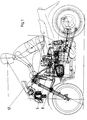
- the motorcycle shown schematically in Fig. 1 is with a so-called ball joint fork equipped. It is a telescopic fork that is on the top End connected to the front frame of the motorcycle rotatably and pivotably and is guided by a trailing arm 8.
- the trailing arm 8 has a strut 6 supported against the front frame. Because such training and leadership a ball joint fork belongs to the prior art, is a more detailed explanation dispensable.
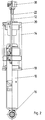
- Fig. 2 shows a partially sectioned side view of the suspension for the front wheel serving shock absorber.
- This strut is made in a manner known per se basically of three parts, namely a damper housing 10, a piston rod 12 and a coil spring 14.
- the piston rod 12 is in the damper housing 10 led to an axial movement and arranged with one in the damper housing hydraulic damper mechanism connected.
- the damper housing 10 is with a Strut eye 16 for articulated connection with the trailing arm shown in Fig. 1 8 and provided with a lower spring plate 18.
- the piston rod 12 is with a upper spring plate 20 for articulated support on the front frame of the motorcycle Mistake.
- the coil spring 14 is supported on the lower and on the upper spring plate 18, 20 and keeps the piston rod 12 in an extended position relative to the damper housing 10 Status.
- shock absorber The above construction and mode of action of the shock absorber is known to the person skilled in the art common and requires no further explanation.
- the piston rod 12 is included provided an axial bore in which a valve needle 22 is slidably guided.
- the bore is extended by a valve needle 22 surrounding flow channel 24 to form.
- This flow channel 24 is with the upper chamber of the damper housing 10 via a radial bore 26 Piston rod 12 in connection.
- the flow channel 24 thus bypasses the damper mechanism.
- a valve cone 28 is attached with a ring 30 inserted into an end recess of the piston rod 12 cooperates.
- an internal thread provided attachment 32 attached.
- the extension 32 is also with a Provide radial bore into which a compression spring 34 and a ball 36 are inserted.
- the hub 40 of a handwheel 38 is attached to the upper end of the valve needle 22. This hub 40 is provided with an external fine thread and into the extension 32 the piston rod 12 is screwed in.
- the handwheel 38 has an extension 32 overlapping shirt 42, the inner surface of which is provided with axial locking grooves 44 is.
- the damping properties of the Shock absorber By turning the handwheel 38, the damping properties of the Shock absorber to be changed.
- the valve needle 22 opposite the piston rod 12 in one or in the other direction axially adjusted so that the between the valve cone 28 and the Ring 30 limited free cross section of the flow channel 24 enlarged or reduced becomes.
- the larger this free cross section the more hydraulic fluid can bypassing the damping mechanism between the two chambers of the Overflow damper housing 10, with the result that the damping effect decreases.
- the upper end of the piston rod 12 extends behind the steering head through a corresponding recess in the fuel tank upwards so that it is in the field of vision and grip of the person sitting on the motorcycle Driver.
- the driver can therefore without dismounting the damping properties adjust the shock absorber in a simple manner by turning the handwheel 38.
Landscapes
- Engineering & Computer Science (AREA)
- Mechanical Engineering (AREA)
- General Engineering & Computer Science (AREA)
- Fluid-Damping Devices (AREA)
- Axle Suspensions And Sidecars For Cycles (AREA)
Applications Claiming Priority (2)
| Application Number | Priority Date | Filing Date | Title |
|---|---|---|---|
| DE19701272A DE19701272A1 (de) | 1997-01-16 | 1997-01-16 | Federbein zur Federung des Vorderrades eines Motorrades |
| DE19701272 | 1997-01-16 |
Publications (3)
| Publication Number | Publication Date |
|---|---|
| EP0854079A2 true EP0854079A2 (fr) | 1998-07-22 |
| EP0854079A3 EP0854079A3 (fr) | 2001-05-02 |
| EP0854079B1 EP0854079B1 (fr) | 2003-03-26 |
Family
ID=7817502
Family Applications (1)
| Application Number | Title | Priority Date | Filing Date |
|---|---|---|---|
| EP97121311A Expired - Lifetime EP0854079B1 (fr) | 1997-01-16 | 1997-12-04 | Jambe de suspension pour la suspension de roue avant pour motocyclette |
Country Status (2)
| Country | Link |
|---|---|
| EP (1) | EP0854079B1 (fr) |
| DE (2) | DE19701272A1 (fr) |
Families Citing this family (1)
| Publication number | Priority date | Publication date | Assignee | Title |
|---|---|---|---|---|
| DE19832324A1 (de) * | 1998-07-17 | 2000-01-20 | Bayerische Motoren Werke Ag | Einstelleinrichtung für ein Federbein eines Motorrads |
Family Cites Families (8)
| Publication number | Priority date | Publication date | Assignee | Title |
|---|---|---|---|---|
| CH317338A (de) * | 1952-10-25 | 1956-11-15 | Bayerische Motoren Werke Ag | Einrichtung zur Abfederung der Hinterradschwinge am Rahmen von Krafträdern |
| DE3623567A1 (de) * | 1986-07-12 | 1988-01-21 | Hubert Kuepper | Vorderradaufhaengung fuer motorraeder |
| DE3708579C2 (de) * | 1987-03-17 | 1996-01-18 | Bayerische Motoren Werke Ag | Vorderradführung für Motorräder |
| DE3914297A1 (de) * | 1989-04-29 | 1990-10-31 | Boge Ag | Regelbarer schwingungsdaempfer fuer kraftfahrzeuge |
| GB8921962D0 (en) * | 1989-09-28 | 1989-11-15 | Browning Michael R S | Variable suspension system |
| DE4137176C2 (de) * | 1991-11-12 | 1993-10-28 | Industrieanlagen Betriebsges | Kennlinienvariables Stoß- und Schwingungsdämpfersystem |
| DE4429562C2 (de) * | 1994-08-19 | 1998-03-19 | Stefan Maier | Hydraulischer Schwingungsdämpfer für das gefederte Vorderrad eines Fahrrads |
| DE19501490A1 (de) * | 1995-01-19 | 1996-07-25 | Hunger Walter Dr Ing E H | Hydropneumatisches Federbein, insbesondere für eine Gabel eines Fahrrades |
-
1997
- 1997-01-16 DE DE19701272A patent/DE19701272A1/de not_active Withdrawn
- 1997-12-04 DE DE59709628T patent/DE59709628D1/de not_active Expired - Lifetime
- 1997-12-04 EP EP97121311A patent/EP0854079B1/fr not_active Expired - Lifetime
Non-Patent Citations (1)
| Title |
|---|
| None |
Also Published As
| Publication number | Publication date |
|---|---|
| EP0854079B1 (fr) | 2003-03-26 |
| EP0854079A3 (fr) | 2001-05-02 |
| DE19701272A1 (de) | 1998-07-23 |
| DE59709628D1 (de) | 2003-04-30 |
Similar Documents
| Publication | Publication Date | Title |
|---|---|---|
| DE60035226T2 (de) | Dämpfungsverbesserungssystem für ein Fahrrad | |
| DE10234906B4 (de) | Einstellung der Kompressionsdämpfung eines Stossdämpfers | |
| DE69019377T2 (de) | Höhenverstellbarer Motorradrahmen. | |
| EP2186718B1 (fr) | Fourche à ressort pour un vélo | |
| DE4219141C2 (de) | Hydraulischer Dämpfer | |
| DE19807210B4 (de) | Stufenlos verstellbarer Stoßdämpfer | |
| DE69930708T2 (de) | Stossdämpfer | |
| DE3034103C2 (fr) | ||
| EP2187085B1 (fr) | Fourche à ressort pour un vélo | |
| DE2604809C3 (de) | Federung mit selbsttätig veränderbarer Federrate für Kraftfahrzeuge, insbesondere Personenkraftwagen | |
| DE19922808A1 (de) | Dämpfungseinrichtung für eine Fahrradgabel | |
| DE10025901B4 (de) | Fahrrad | |
| DE3231739A1 (de) | Zweirohr-schwingungsdaempfer oder federbein mit veraenderbarer daempfkraft | |
| DE3781147T2 (de) | Regelbarer stossdaempfer. | |
| DE19857595A1 (de) | Selbstpumpendes hydropneumatisches Federbein mit innerer Niveauregelung | |
| DE4429562C2 (de) | Hydraulischer Schwingungsdämpfer für das gefederte Vorderrad eines Fahrrads | |
| DE3630757C2 (fr) | ||
| DE2754777A1 (de) | Radaufhaengungsvorrichtung fuer ein fahrzeug | |
| DE10319390B4 (de) | Hydraulischer Stoßdämpfer | |
| DE2757711C2 (de) | Hydraulischer Teleskopstoßdämpfer für ein Motorrad | |
| EP1964695B1 (fr) | Unité d'amortissement et de ressort à air avec élément de commande | |
| DE19532510C2 (de) | Teleskopschwingungsdämpfer, insbesondere für Kraftfahrzeuge | |
| DE4117461A1 (de) | Stossdaempfer mit variabler daempfungskraft | |
| DE19501490A1 (de) | Hydropneumatisches Federbein, insbesondere für eine Gabel eines Fahrrades | |
| EP0854079A2 (fr) | Jambe de suspension pour la suspension de roue avant pour motocyclette |
Legal Events
| Date | Code | Title | Description |
|---|---|---|---|
| PUAI | Public reference made under article 153(3) epc to a published international application that has entered the european phase |
Free format text: ORIGINAL CODE: 0009012 |
|
| AK | Designated contracting states |
Kind code of ref document: A2 Designated state(s): DE FR GB IT |
|
| AX | Request for extension of the european patent |
Free format text: AL;LT;LV;MK;RO;SI |
|
| PUAL | Search report despatched |
Free format text: ORIGINAL CODE: 0009013 |
|
| AK | Designated contracting states |
Kind code of ref document: A3 Designated state(s): AT BE CH DE DK ES FI FR GB GR IE IT LI LU MC NL PT SE |
|
| AX | Request for extension of the european patent |
Free format text: AL;LT;LV;MK;RO;SI |
|
| 17P | Request for examination filed |
Effective date: 20010321 |
|
| AKX | Designation fees paid |
Free format text: DE FR GB IT |
|
| 17Q | First examination report despatched |
Effective date: 20020328 |
|
| GRAH | Despatch of communication of intention to grant a patent |
Free format text: ORIGINAL CODE: EPIDOS IGRA |
|
| GRAH | Despatch of communication of intention to grant a patent |
Free format text: ORIGINAL CODE: EPIDOS IGRA |
|
| GRAA | (expected) grant |
Free format text: ORIGINAL CODE: 0009210 |
|
| AK | Designated contracting states |
Designated state(s): DE FR GB IT |
|
| REG | Reference to a national code |
Ref country code: GB Ref legal event code: FG4D Free format text: NOT ENGLISH |
|
| REF | Corresponds to: |
Ref document number: 59709628 Country of ref document: DE Date of ref document: 20030430 Kind code of ref document: P |
|
| GBT | Gb: translation of ep patent filed (gb section 77(6)(a)/1977) |
Effective date: 20030507 |
|
| ET | Fr: translation filed | ||
| PLBE | No opposition filed within time limit |
Free format text: ORIGINAL CODE: 0009261 |
|
| STAA | Information on the status of an ep patent application or granted ep patent |
Free format text: STATUS: NO OPPOSITION FILED WITHIN TIME LIMIT |
|
| 26N | No opposition filed |
Effective date: 20031230 |
|
| PGFP | Annual fee paid to national office [announced via postgrant information from national office to epo] |
Ref country code: GB Payment date: 20101230 Year of fee payment: 14 |
|
| PGFP | Annual fee paid to national office [announced via postgrant information from national office to epo] |
Ref country code: IT Payment date: 20101230 Year of fee payment: 14 Ref country code: FR Payment date: 20110119 Year of fee payment: 14 Ref country code: DE Payment date: 20110129 Year of fee payment: 14 |
|
| GBPC | Gb: european patent ceased through non-payment of renewal fee |
Effective date: 20111204 |
|
| REG | Reference to a national code |
Ref country code: FR Ref legal event code: ST Effective date: 20120831 |
|
| PG25 | Lapsed in a contracting state [announced via postgrant information from national office to epo] |
Ref country code: GB Free format text: LAPSE BECAUSE OF NON-PAYMENT OF DUE FEES Effective date: 20111204 Ref country code: DE Free format text: LAPSE BECAUSE OF NON-PAYMENT OF DUE FEES Effective date: 20120703 |
|
| REG | Reference to a national code |
Ref country code: DE Ref legal event code: R119 Ref document number: 59709628 Country of ref document: DE Effective date: 20120703 |
|
| PG25 | Lapsed in a contracting state [announced via postgrant information from national office to epo] |
Ref country code: IT Free format text: LAPSE BECAUSE OF NON-PAYMENT OF DUE FEES Effective date: 20111204 |
|
| PG25 | Lapsed in a contracting state [announced via postgrant information from national office to epo] |
Ref country code: FR Free format text: LAPSE BECAUSE OF NON-PAYMENT OF DUE FEES Effective date: 20120102 |