EP0854079A2 - Suspension strut for motorcycle front wheel suspension - Google Patents
Suspension strut for motorcycle front wheel suspension Download PDFInfo
- Publication number
- EP0854079A2 EP0854079A2 EP97121311A EP97121311A EP0854079A2 EP 0854079 A2 EP0854079 A2 EP 0854079A2 EP 97121311 A EP97121311 A EP 97121311A EP 97121311 A EP97121311 A EP 97121311A EP 0854079 A2 EP0854079 A2 EP 0854079A2
- Authority
- EP
- European Patent Office
- Prior art keywords
- piston rod
- valve needle
- suspension
- valve
- flow channel
- Prior art date
- Legal status (The legal status is an assumption and is not a legal conclusion. Google has not performed a legal analysis and makes no representation as to the accuracy of the status listed.)
- Granted
Links
- 239000000725 suspension Substances 0.000 title claims description 11
- 238000013016 damping Methods 0.000 claims description 9
- 230000006835 compression Effects 0.000 claims description 7
- 238000007906 compression Methods 0.000 claims description 7
- 239000006096 absorbing agent Substances 0.000 description 4
- 230000035939 shock Effects 0.000 description 4
- 239000012530 fluid Substances 0.000 description 2
- 238000000034 method Methods 0.000 description 2
- 238000010276 construction Methods 0.000 description 1
- 230000007423 decrease Effects 0.000 description 1
- 239000002828 fuel tank Substances 0.000 description 1
Images

Classifications
-
- B—PERFORMING OPERATIONS; TRANSPORTING
- B62—LAND VEHICLES FOR TRAVELLING OTHERWISE THAN ON RAILS
- B62K—CYCLES; CYCLE FRAMES; CYCLE STEERING DEVICES; RIDER-OPERATED TERMINAL CONTROLS SPECIALLY ADAPTED FOR CYCLES; CYCLE AXLE SUSPENSIONS; CYCLE SIDE-CARS, FORECARS, OR THE LIKE
- B62K25/00—Axle suspensions
- B62K25/04—Axle suspensions for mounting axles resiliently on cycle frame or fork
- B62K25/12—Axle suspensions for mounting axles resiliently on cycle frame or fork with rocking arm pivoted on each fork leg
- B62K25/14—Axle suspensions for mounting axles resiliently on cycle frame or fork with rocking arm pivoted on each fork leg with single arm on each fork leg
- B62K25/16—Axle suspensions for mounting axles resiliently on cycle frame or fork with rocking arm pivoted on each fork leg with single arm on each fork leg for front wheel
-
- B—PERFORMING OPERATIONS; TRANSPORTING
- B62—LAND VEHICLES FOR TRAVELLING OTHERWISE THAN ON RAILS
- B62K—CYCLES; CYCLE FRAMES; CYCLE STEERING DEVICES; RIDER-OPERATED TERMINAL CONTROLS SPECIALLY ADAPTED FOR CYCLES; CYCLE AXLE SUSPENSIONS; CYCLE SIDE-CARS, FORECARS, OR THE LIKE
- B62K25/00—Axle suspensions
- B62K25/04—Axle suspensions for mounting axles resiliently on cycle frame or fork
- B62K25/06—Axle suspensions for mounting axles resiliently on cycle frame or fork with telescopic fork, e.g. including auxiliary rocking arms
- B62K25/08—Axle suspensions for mounting axles resiliently on cycle frame or fork with telescopic fork, e.g. including auxiliary rocking arms for front wheel
-
- F—MECHANICAL ENGINEERING; LIGHTING; HEATING; WEAPONS; BLASTING
- F16—ENGINEERING ELEMENTS AND UNITS; GENERAL MEASURES FOR PRODUCING AND MAINTAINING EFFECTIVE FUNCTIONING OF MACHINES OR INSTALLATIONS; THERMAL INSULATION IN GENERAL
- F16F—SPRINGS; SHOCK-ABSORBERS; MEANS FOR DAMPING VIBRATION
- F16F9/00—Springs, vibration-dampers, shock-absorbers, or similarly-constructed movement-dampers using a fluid or the equivalent as damping medium
- F16F9/32—Details
- F16F9/44—Means on or in the damper for manual or non-automatic adjustment; such means combined with temperature correction
- F16F9/46—Means on or in the damper for manual or non-automatic adjustment; such means combined with temperature correction allowing control from a distance, i.e. location of means for control input being remote from site of valves, e.g. on damper external wall
-
- B—PERFORMING OPERATIONS; TRANSPORTING
- B62—LAND VEHICLES FOR TRAVELLING OTHERWISE THAN ON RAILS
- B62K—CYCLES; CYCLE FRAMES; CYCLE STEERING DEVICES; RIDER-OPERATED TERMINAL CONTROLS SPECIALLY ADAPTED FOR CYCLES; CYCLE AXLE SUSPENSIONS; CYCLE SIDE-CARS, FORECARS, OR THE LIKE
- B62K25/00—Axle suspensions
- B62K25/04—Axle suspensions for mounting axles resiliently on cycle frame or fork
- B62K2025/048—Axle suspensions for mounting axles resiliently on cycle frame or fork with suspension manual adjustment details
Definitions
- the invention relates to a suspension strut for suspension of the front wheel a ball joint fork equipped motorcycle, comprising a damper housing, which contains a hydraulic damper mechanism and a lower spring plate and has a strut eye for articulated connection with a trailing arm, one guided in the damper housing and connected to the damper mechanism Piston rod, which is an upper spring plate for articulated support on a Has front frame, and one on the upper and on the lower spring plate adjacent coil spring.
- the invention has for its object the strut of the aforementioned Kind in such a way that the damping property of the driver of the motorcycle can be changed without having to dismount.
- this object is achieved in that the piston rod is hollow trained and extended beyond the upper spring plate that the Piston rod in the lower area bypassing the damping mechanism
- Flow channel has a valve needle axially movable in the piston rod is arranged that the valve needle at the lower end of a valve body for changing of the free cross section of the flow channel, and that at the upper end of Piston rod a manually operated adjustment device for changing the axial position the valve needle is arranged.
- the bore of the piston rod to form the flow channel is expanded in the lower area and that at the lower end of the valve needle a valve plug is attached.
- This valve cone preferably acts with one in the lower end of the enlarged bore inserted ring together.
- valve needle with the piston rod is connected via a thread.
- Strut is provided that an extension at the upper end of the piston rod is attached with an internal fine thread and with a compression spring and a ball receiving radial bore is provided, and that at the upper end an adjusting handwheel is attached to the valve needle, one with an external fine thread provided hub and a shirt overlapping the extension, the inner surface is provided with locking grooves.
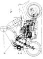
- the motorcycle shown schematically in Fig. 1 is with a so-called ball joint fork equipped. It is a telescopic fork that is on the top End connected to the front frame of the motorcycle rotatably and pivotably and is guided by a trailing arm 8.
- the trailing arm 8 has a strut 6 supported against the front frame. Because such training and leadership a ball joint fork belongs to the prior art, is a more detailed explanation dispensable.
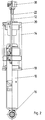
- Fig. 2 shows a partially sectioned side view of the suspension for the front wheel serving shock absorber.
- This strut is made in a manner known per se basically of three parts, namely a damper housing 10, a piston rod 12 and a coil spring 14.
- the piston rod 12 is in the damper housing 10 led to an axial movement and arranged with one in the damper housing hydraulic damper mechanism connected.
- the damper housing 10 is with a Strut eye 16 for articulated connection with the trailing arm shown in Fig. 1 8 and provided with a lower spring plate 18.
- the piston rod 12 is with a upper spring plate 20 for articulated support on the front frame of the motorcycle Mistake.
- the coil spring 14 is supported on the lower and on the upper spring plate 18, 20 and keeps the piston rod 12 in an extended position relative to the damper housing 10 Status.
- shock absorber The above construction and mode of action of the shock absorber is known to the person skilled in the art common and requires no further explanation.
- the piston rod 12 is included provided an axial bore in which a valve needle 22 is slidably guided.
- the bore is extended by a valve needle 22 surrounding flow channel 24 to form.
- This flow channel 24 is with the upper chamber of the damper housing 10 via a radial bore 26 Piston rod 12 in connection.
- the flow channel 24 thus bypasses the damper mechanism.
- a valve cone 28 is attached with a ring 30 inserted into an end recess of the piston rod 12 cooperates.
- an internal thread provided attachment 32 attached.
- the extension 32 is also with a Provide radial bore into which a compression spring 34 and a ball 36 are inserted.
- the hub 40 of a handwheel 38 is attached to the upper end of the valve needle 22. This hub 40 is provided with an external fine thread and into the extension 32 the piston rod 12 is screwed in.
- the handwheel 38 has an extension 32 overlapping shirt 42, the inner surface of which is provided with axial locking grooves 44 is.
- the damping properties of the Shock absorber By turning the handwheel 38, the damping properties of the Shock absorber to be changed.
- the valve needle 22 opposite the piston rod 12 in one or in the other direction axially adjusted so that the between the valve cone 28 and the Ring 30 limited free cross section of the flow channel 24 enlarged or reduced becomes.
- the larger this free cross section the more hydraulic fluid can bypassing the damping mechanism between the two chambers of the Overflow damper housing 10, with the result that the damping effect decreases.
- the upper end of the piston rod 12 extends behind the steering head through a corresponding recess in the fuel tank upwards so that it is in the field of vision and grip of the person sitting on the motorcycle Driver.
- the driver can therefore without dismounting the damping properties adjust the shock absorber in a simple manner by turning the handwheel 38.
Landscapes
- Engineering & Computer Science (AREA)
- Mechanical Engineering (AREA)
- General Engineering & Computer Science (AREA)
- Fluid-Damping Devices (AREA)
- Axle Suspensions And Sidecars For Cycles (AREA)
Abstract
Description
Die Erfindung betrifft ein Federbein zur Federung des Vorderrades eines mit einer Kugelgelenkgabel ausgerüsteten Motorrades, umfassend ein Dämpfergehäuse, das einen hydraulischen Dämpfermechanismus enthält und einen unteren Federteller sowie ein Federbeinauge zur gelenkigen Verbindung mit einem Längslenker aufweist, eine in dem Dämpfergehäuse geführte und mit dem Dämpfermechanismus verbundene Kolbenstange, die einen oberen Federteller zur gelenkigen Abstützung an einem Vorderrahmen aufweist, und eine an dem oberen und an dem unteren Federteller anliegende Schraubenfeder.The invention relates to a suspension strut for suspension of the front wheel a ball joint fork equipped motorcycle, comprising a damper housing, which contains a hydraulic damper mechanism and a lower spring plate and has a strut eye for articulated connection with a trailing arm, one guided in the damper housing and connected to the damper mechanism Piston rod, which is an upper spring plate for articulated support on a Has front frame, and one on the upper and on the lower spring plate adjacent coil spring.
Es sind bereits Federbeine zur Federung eines Motorrades bekannt, die mit einer Verstelleinrichtung versehen sind, um die Dämpfungseigenschaft zu verändern. Diese Verstelleinrichtung kann im Dämpfergehäuse oder an einem mit diesem über einen Schlauch verbundenen Ausgleichsbehälter angebracht sein. In beiden Fällen ist eine Betätigung der Verstelleinrichtung nur bei aufgebocktem, stillstehendem Fahrzeug möglich, und es ist zumeist ein besonderes Werkzeug erforderlich.There are already known struts for suspension of a motorcycle, with an adjustment device are provided to change the damping property. This adjustment device can be in the damper housing or on one with it a hose connected expansion tank may be attached. In both cases actuation of the adjustment device only when the vehicle is jacked up and stationary possible, and usually a special tool is required.
Der Erfindung liegt die Aufgabe zugrunde, das Federbein der eingangs genannten Art dahingehend weiterzubilden, daß die Dämpfungseigenschaft vom Fahrer des Motorrades verändert werden kann, ohne absteigen zu müssen. The invention has for its object the strut of the aforementioned Kind in such a way that the damping property of the driver of the Motorcycle can be changed without having to dismount.
Erfindungsgemäß wird diese Aufgabe dadurch gelöst, daß die Kolbenstange hohl ausgebildet und über den oberen Federteller hinaus nach oben verlängert ist, daß die Kolbenstange im unteren Bereich einen den Dämpfungsmechanismus umgehenden Strömungskanal aufweist, daß in der Kolbenstange eine Ventilnadel axial beweglich angeordnet ist, daß die Ventilnadel am unteren Ende einen Ventilkörper zum Verändern des freien Querschnitts des Strömungskanals aufweist, und daß am oberen Ende der Kolbenstange eine manuell betätigbare Einstelleinrichtung zum Verändern der Axialstellung der Ventilnadel angeordnet ist.According to the invention, this object is achieved in that the piston rod is hollow trained and extended beyond the upper spring plate that the Piston rod in the lower area bypassing the damping mechanism Flow channel has a valve needle axially movable in the piston rod is arranged that the valve needle at the lower end of a valve body for changing of the free cross section of the flow channel, and that at the upper end of Piston rod a manually operated adjustment device for changing the axial position the valve needle is arranged.
Bei einem derartig ausgebildeten Federbein kann der Fahrer des Motorrades die Dämpfungscharakteristik ohne Verwendung eines besonderen Werkzeugs im Bedarfsfall verändern, ohne absteigen zu müssen.With such a strut, the driver of the motorcycle can Damping characteristics without the use of a special tool if necessary change without having to dismount.
Bei einer in konstruktiver Hinsicht besonders vorteilhatten Ausführungsform der Erfindung ist vorgesehen, daß die Bohrung der Kolbenstange zur Bildung des Strömungskanals im unteren Bereich erweitert ist und daß am unteren Ende der Ventilnadel ein Ventilkegel befestigt ist. Dieser Ventilkegel wirkt vorzugsweise mit einem in das untere Ende der erweiterten Bohrung eingesetzten Ring zusammen.In a particularly advantageous embodiment of the embodiment of the Invention is provided that the bore of the piston rod to form the flow channel is expanded in the lower area and that at the lower end of the valve needle a valve plug is attached. This valve cone preferably acts with one in the lower end of the enlarged bore inserted ring together.
Im Hinblick auf eine einfache Veränderung der Axialstellung der Ventilnadel innerhalb der Kolbenstange ist vorgesehen, daß die Ventilnadel mit der Kolbenstange über ein Gewinde verbunden ist.With regard to a simple change in the axial position of the valve needle it is provided within the piston rod that the valve needle with the piston rod is connected via a thread.
Bei einer besonders bedienungsfreundlichen Ausführungsform des erfindungsgemäßen Federbeins ist vorgesehen, daß am oberen Ende der Kolbenstange ein Ansatzstück befestigt ist, das mit einem Innenfeingewinde und mit einer eine Druckfeder und eine Kugel aufnehmenden Radialbohrung versehen ist, und daß am oberen Ende der Ventilnadel ein Einstell-Handrad befestigt ist, das eine mit einem Außenfeingewinde versehene Nabe und ein das Ansatzstück übergreifendes Hemd umfaßt, dessen Innenfläche mit Rastnuten versehen ist.In a particularly user-friendly embodiment of the invention Strut is provided that an extension at the upper end of the piston rod is attached with an internal fine thread and with a compression spring and a ball receiving radial bore is provided, and that at the upper end an adjusting handwheel is attached to the valve needle, one with an external fine thread provided hub and a shirt overlapping the extension, the inner surface is provided with locking grooves.
Ein Ausführungsbeispiel der Erfindung ist in der Zeichnung dargestellt und wird
nachfolgend näher erläutert. Es zeigt:
Das in Fig. 1 schematisch dargestellte Motorrad ist mit einer sogenannten Kugelgelenkgabel
ausgerüstet. Dabei handelt es sich um eine Teleskopgabel, die am oberen
Ende mit dem Vorderrahmen des Motorrades dreh- und schwenkbar verbunden und
durch einen Längslenker 8 geführt ist. Der Längslenker 8 ist mit einem Federbein 6
gegenüber dem Vorderrahmen abgestützt. Da eine derartige Ausbildung und Führung
einer Kugelgelenkgabel zum Stand der Technik gehört, ist eine nähere Erläuterung
entbehrlich.The motorcycle shown schematically in Fig. 1 is with a so-called ball joint fork
equipped. It is a telescopic fork that is on the top
End connected to the front frame of the motorcycle rotatably and pivotably and
is guided by a
Fig. 2 zeigt eine teilweise geschnittene Seitenansicht des zur Federung des Vorderrades
dienenden Federbeins. Dieses Federbein besteht in an sich bekannter Weise
grundsätzlich aus drei Teilen, nämlich einem Dämpfergehäuse 10, einer Kolbenstange
12 und einer Schraubenfeder 14. Die Kolbenstange 12 ist in dem Dämpfergehäuse 10
zu einer Axialbewegung geführt und mit einem in dem Dämpfergehäuse angeordneten
hydraulischen Dämpfermechanismus verbunden. Das Dämpfergehäuse 10 ist mit einem
Federbeinauge 16 zur gelenkigen Verbindung mit dem in Fig. 1 gezeigten Längslenker
8 und mit einem unteren Federteller 18 versehen. Die Kolbenstange 12 ist mit einem
oberen Federteller 20 zur gelenkigen Abstützung am Vorderrahmen des Motorrades
versehen. Die Schraubenfeder 14 stützt sich am unteren und am oberen Federteller 18,
20 ab und hält die Kolbenstange 12 gegenüber dem Dämpfergehäuse 10 in einem ausgefahrenen
Zustand.Fig. 2 shows a partially sectioned side view of the suspension for the front wheel
serving shock absorber. This strut is made in a manner known per se
basically of three parts, namely a
Wenn auf das Vorderrad des Motorrades und damit über die Teleskopgabel und
den Längslenker 8 auf das Federbeinauge 16 eine vertikale Kraft ausgeübt wird, dann
wird das Dämpfergehäuse 10 unter Kompression der Schraubenfeder 14 gegenüber
der Kolbenstange 12 nach oben bewegt. Dieser Vorgang wird als Einfedern bezeichnet.
Wenn die auf das Federbeinauge 16 ausgeübte Axialkraft aufgehoben wird, dann kann
sich die Schraubenfeder 14 entspannen, und das Dämpfergehäuse 10 bewegt sich
gegenüber der feststehenden Kolbenstange 12 nach unten. Dieser Vorgang wird als
Ausfedern bezeichnet. Die Relativbewegung beim Ein- und Ausfedern wird durch den
im Dämpfergehäuse 10 angeordneten und mit der Kolbenstange 12 verbundenen
Dämpfermechanismus gedämpft. Ein solcher Dämpfermechanismus besteht grundsätzlich
aus einem mit der Kolbenstange 12 verbundenen Kolben, der mit Überströmkanälen
versehen ist, die ein gebremstes Überströmen der Hydraulikflüssigkeit von der
sich verkleinernden Kammer in die sich vergrößernde Kammer des Dämpfergehäuses
10 beiderseits des Kolbens ermöglichen.When on the front wheel of the motorcycle and thus on the telescopic fork and
the
Die vorstehende Konstruktion und Wirkungsweise des Federbeins ist dem Fachmann geläufig und bedarf keiner weiteren Erläuterung.The above construction and mode of action of the shock absorber is known to the person skilled in the art common and requires no further explanation.
Wie dies deutlicher aus den Fig. 3 und 4 hervorgeht, ist die Kolbenstange 12 mit
einer Axialbohrung versehen, in der eine Ventilnadel 22 verschiebbar geführt ist. Im
unteren Endbereich der Kolbenstange 12 ist die Bohrung erweitert, um einen die Ventilnadel
22 umgebenden Strömungskanal 24 zu bilden. Dieser Strömungskanal 24 steht
mit der oberen Kammer des Dämpfergehäuses 10 über eine radiale Bohrung 26 der
Kolbenstange 12 in Verbindung. Der Strömungskanal 24 umgeht somit den Dämpfermechanismus.
Am unteren Ende der Ventilnadel 22 ist ein Ventilkegel 28 befestigt, der
mit einem in eine endseitige Ausnehmung der Kolbenstange 12 eingesetzten Ring 30
zusammenwirkt. Am oberen Ende der Kolbenstange 12 ist ein mit einem Innenfeingewinde
versehenes Ansatzstück 32 befestigt. Das Ansatzstück 32 ist ferner mit einer
Radialbohrung versehen, in die eine Druckfeder 34 und eine Kugel 36 eingesetzt sind.
Am oberen Ende der Ventilnadel 22 ist die Nabe 40 eines Handrades 38 befestigt.
Diese Nabe 40 ist mit einem Außenfeingewinde versehen und in das Ansatzstück 32
der Kolbenstange 12 eingeschraubt. Das Handrad 38 weist ein das Ansatzstück 32
übergreifendes Hemd 42 auf, dessen Innenfläche mit axialen Rastnuten 44 versehen
ist.As can be seen more clearly from FIGS. 3 and 4, the
Durch Verdrehen des Handrades 38 können die Dämpfungseigenschaften des
Federbeins verändert werden. Je nachdem, in welcher Richtung das Handrad 38 verdreht
wird, wird die Ventilnadel 22 gegenüber der Kolbenstange 12 in der einen oder in
der anderen Richtung axial verstellt, so daß der zwischen dem Ventilkegel 28 und dem
Ring 30 begrenzte freie Querschnitt des Strömungskanals 24 vergrößert oder verkleinert
wird. Je größer dieser freie Querschnitt ist, desto mehr Hydraulikflüssigkeit kann
unter Umgehung des Dämpfungsmechanismus zwischen den beiden Kammern des
Dämpfergehäuses 10 überströmen, mit der Folge, daß die Dämpfungswirkung abnimmt. By turning the
Wie aus Fig. 1 hervorgeht, erstreckt sich das obere Ende der Kolbenstange 12
hinter dem Lenkkopf durch eine entsprechende Aussparung des Kraftstoffbehälters
nach oben, so daß es sich im Sicht- und Griffbereich des auf dem Motorrad sitzenden
Fahrers befindet. Der Fahrer kann daher ohne abzusteigen die Dämpfungseigenschaften
des Federbeins durch Verdrehen des Handrades 38 auf einfache Weise verstellen. 1, the upper end of the
- 1010th
- DämpfergehäuseDamper housing
- 1212th
- KolbenstangePiston rod
- 1414
- SchraubenfederCoil spring
- 1616
- FederbeinaugeStrut eye
- 1818th
- unterer Federtellerlower spring plate
- 2020th
- oberer Federtellerupper spring plate
- 2222
- VentilnadelValve needle
- 2424th
- StrömungskanalFlow channel
- 2626
- radiale Bohrungradial bore
- 2828
- VentilkegelValve cone
- 3030th
- Ringring
- 3232
- AnsatzstückExtension
- 3434
- DruckfederCompression spring
- 3636
- KugelBullet
- 3838
- HandradHandwheel
- 4040
- Nabehub
- 4242
- Hemdshirt
- 4444
- RastnutenLocking grooves
Claims (5)
Applications Claiming Priority (2)
| Application Number | Priority Date | Filing Date | Title |
|---|---|---|---|
| DE19701272A DE19701272A1 (en) | 1997-01-16 | 1997-01-16 | Suspension strut for suspension of the front wheel of a motorcycle |
| DE19701272 | 1997-01-16 |
Publications (3)
| Publication Number | Publication Date |
|---|---|
| EP0854079A2 true EP0854079A2 (en) | 1998-07-22 |
| EP0854079A3 EP0854079A3 (en) | 2001-05-02 |
| EP0854079B1 EP0854079B1 (en) | 2003-03-26 |
Family
ID=7817502
Family Applications (1)
| Application Number | Title | Priority Date | Filing Date |
|---|---|---|---|
| EP97121311A Expired - Lifetime EP0854079B1 (en) | 1997-01-16 | 1997-12-04 | Suspension strut for motorcycle front wheel suspension |
Country Status (2)
| Country | Link |
|---|---|
| EP (1) | EP0854079B1 (en) |
| DE (2) | DE19701272A1 (en) |
Families Citing this family (1)
| Publication number | Priority date | Publication date | Assignee | Title |
|---|---|---|---|---|
| DE19832324A1 (en) | 1998-07-17 | 2000-01-20 | Bayerische Motoren Werke Ag | Adjustment device for a shock absorber of a motorcycle |
Family Cites Families (8)
| Publication number | Priority date | Publication date | Assignee | Title |
|---|---|---|---|---|
| CH317338A (en) * | 1952-10-25 | 1956-11-15 | Bayerische Motoren Werke Ag | Device for cushioning the rear swing arm on the frame of motorcycles |
| DE3623567A1 (en) * | 1986-07-12 | 1988-01-21 | Hubert Kuepper | Front-wheel suspension for motorcycles |
| DE3708579C2 (en) * | 1987-03-17 | 1996-01-18 | Bayerische Motoren Werke Ag | Front wheel guide for motorcycles |
| DE3914297A1 (en) * | 1989-04-29 | 1990-10-31 | Boge Ag | ADJUSTABLE VIBRATION DAMPER FOR MOTOR VEHICLES |
| GB8921962D0 (en) * | 1989-09-28 | 1989-11-15 | Browning Michael R S | Variable suspension system |
| DE4137176C2 (en) * | 1991-11-12 | 1993-10-28 | Industrieanlagen Betriebsges | Characteristic variable shock and vibration damper system |
| DE4429562C2 (en) * | 1994-08-19 | 1998-03-19 | Stefan Maier | Hydraulic vibration damper for the sprung front wheel of a bicycle |
| DE19501490A1 (en) * | 1995-01-19 | 1996-07-25 | Hunger Walter Dr Ing E H | Hydropneumatic shock absorber, especially for a fork of a bicycle |
-
1997
- 1997-01-16 DE DE19701272A patent/DE19701272A1/en not_active Withdrawn
- 1997-12-04 DE DE59709628T patent/DE59709628D1/en not_active Expired - Lifetime
- 1997-12-04 EP EP97121311A patent/EP0854079B1/en not_active Expired - Lifetime
Non-Patent Citations (1)
| Title |
|---|
| None |
Also Published As
| Publication number | Publication date |
|---|---|
| DE19701272A1 (en) | 1998-07-23 |
| DE59709628D1 (en) | 2003-04-30 |
| EP0854079B1 (en) | 2003-03-26 |
| EP0854079A3 (en) | 2001-05-02 |
Similar Documents
| Publication | Publication Date | Title |
|---|---|---|
| DE60035226T2 (en) | Damping improvement system for a bicycle | |
| DE10234906B4 (en) | Adjustment of the compression damping of a shock absorber | |
| DE69019377T2 (en) | Height adjustable motorcycle frame. | |
| EP2186718B1 (en) | Suspension fork for a bicycle | |
| DE4219141C2 (en) | Hydraulic damper | |
| DE19807210B4 (en) | Infinitely adjustable shock absorber | |
| DE69930708T2 (en) | shock absorber | |
| DE3034103C2 (en) | ||
| EP2187085B1 (en) | Suspension fork for a bicycle | |
| DE2604809C3 (en) | Suspension with automatically variable spring rate for motor vehicles, in particular passenger cars | |
| DE19922808A1 (en) | Damping device for bicycle fork | |
| DE3231739A1 (en) | TWO TUBE VIBRATION DAMPER OR SHOCK ABSORBER WITH VARIABLE DAMPING FORCE | |
| DE10025901B4 (en) | bicycle | |
| DE3781147T2 (en) | ADJUSTABLE SHOCK ABSORBER. | |
| DE19857595A1 (en) | Piston pump of hydro-pneumatically operated strut is equipped with pressure relief valve | |
| DE4429562C2 (en) | Hydraulic vibration damper for the sprung front wheel of a bicycle | |
| DE3630757C2 (en) | ||
| DE2754777A1 (en) | WHEEL SUSPENSION DEVICE FOR A VEHICLE | |
| DE10319390B4 (en) | Hydraulic shock absorber | |
| DE2757711C2 (en) | Hydraulic telescopic shock absorber for a motorcycle | |
| EP1964695B1 (en) | Pneumatic spring and damping unit with operating element | |
| DE19532510C2 (en) | Telescopic vibration damper, in particular for motor vehicles | |
| DE4117461A1 (en) | SHOCK ABSORBER WITH VARIABLE DAMPING FORCE | |
| DE19501490A1 (en) | Hydropneumatic shock absorber, especially for a fork of a bicycle | |
| EP0854079A2 (en) | Suspension strut for motorcycle front wheel suspension |
Legal Events
| Date | Code | Title | Description |
|---|---|---|---|
| PUAI | Public reference made under article 153(3) epc to a published international application that has entered the european phase |
Free format text: ORIGINAL CODE: 0009012 |
|
| AK | Designated contracting states |
Kind code of ref document: A2 Designated state(s): DE FR GB IT |
|
| AX | Request for extension of the european patent |
Free format text: AL;LT;LV;MK;RO;SI |
|
| PUAL | Search report despatched |
Free format text: ORIGINAL CODE: 0009013 |
|
| AK | Designated contracting states |
Kind code of ref document: A3 Designated state(s): AT BE CH DE DK ES FI FR GB GR IE IT LI LU MC NL PT SE |
|
| AX | Request for extension of the european patent |
Free format text: AL;LT;LV;MK;RO;SI |
|
| 17P | Request for examination filed |
Effective date: 20010321 |
|
| AKX | Designation fees paid |
Free format text: DE FR GB IT |
|
| 17Q | First examination report despatched |
Effective date: 20020328 |
|
| GRAH | Despatch of communication of intention to grant a patent |
Free format text: ORIGINAL CODE: EPIDOS IGRA |
|
| GRAH | Despatch of communication of intention to grant a patent |
Free format text: ORIGINAL CODE: EPIDOS IGRA |
|
| GRAA | (expected) grant |
Free format text: ORIGINAL CODE: 0009210 |
|
| AK | Designated contracting states |
Designated state(s): DE FR GB IT |
|
| REG | Reference to a national code |
Ref country code: GB Ref legal event code: FG4D Free format text: NOT ENGLISH |
|
| REF | Corresponds to: |
Ref document number: 59709628 Country of ref document: DE Date of ref document: 20030430 Kind code of ref document: P |
|
| GBT | Gb: translation of ep patent filed (gb section 77(6)(a)/1977) |
Effective date: 20030507 |
|
| ET | Fr: translation filed | ||
| PLBE | No opposition filed within time limit |
Free format text: ORIGINAL CODE: 0009261 |
|
| STAA | Information on the status of an ep patent application or granted ep patent |
Free format text: STATUS: NO OPPOSITION FILED WITHIN TIME LIMIT |
|
| 26N | No opposition filed |
Effective date: 20031230 |
|
| PGFP | Annual fee paid to national office [announced via postgrant information from national office to epo] |
Ref country code: GB Payment date: 20101230 Year of fee payment: 14 |
|
| PGFP | Annual fee paid to national office [announced via postgrant information from national office to epo] |
Ref country code: IT Payment date: 20101230 Year of fee payment: 14 Ref country code: FR Payment date: 20110119 Year of fee payment: 14 Ref country code: DE Payment date: 20110129 Year of fee payment: 14 |
|
| GBPC | Gb: european patent ceased through non-payment of renewal fee |
Effective date: 20111204 |
|
| REG | Reference to a national code |
Ref country code: FR Ref legal event code: ST Effective date: 20120831 |
|
| PG25 | Lapsed in a contracting state [announced via postgrant information from national office to epo] |
Ref country code: GB Free format text: LAPSE BECAUSE OF NON-PAYMENT OF DUE FEES Effective date: 20111204 Ref country code: DE Free format text: LAPSE BECAUSE OF NON-PAYMENT OF DUE FEES Effective date: 20120703 |
|
| REG | Reference to a national code |
Ref country code: DE Ref legal event code: R119 Ref document number: 59709628 Country of ref document: DE Effective date: 20120703 |
|
| PG25 | Lapsed in a contracting state [announced via postgrant information from national office to epo] |
Ref country code: IT Free format text: LAPSE BECAUSE OF NON-PAYMENT OF DUE FEES Effective date: 20111204 |
|
| PG25 | Lapsed in a contracting state [announced via postgrant information from national office to epo] |
Ref country code: FR Free format text: LAPSE BECAUSE OF NON-PAYMENT OF DUE FEES Effective date: 20120102 |