EP0852409B1 - Antenna apparatus and transmission and receiving apparatus using same - Google Patents
Antenna apparatus and transmission and receiving apparatus using same Download PDFInfo
- Publication number
- EP0852409B1 EP0852409B1 EP98100074A EP98100074A EP0852409B1 EP 0852409 B1 EP0852409 B1 EP 0852409B1 EP 98100074 A EP98100074 A EP 98100074A EP 98100074 A EP98100074 A EP 98100074A EP 0852409 B1 EP0852409 B1 EP 0852409B1
- Authority
- EP
- European Patent Office
- Prior art keywords
- dielectric
- primary radiator
- transmission
- antenna
- line
- Prior art date
- Legal status (The legal status is an assumption and is not a legal conclusion. Google has not performed a legal analysis and makes no representation as to the accuracy of the status listed.)
- Expired - Lifetime
Links
Images


Classifications
-
- H—ELECTRICITY
- H01—ELECTRIC ELEMENTS
- H01Q—ANTENNAS, i.e. RADIO AERIALS
- H01Q19/00—Combinations of primary active antenna elements and units with secondary devices, e.g. with quasi-optical devices, for giving the antenna a desired directional characteristic
- H01Q19/06—Combinations of primary active antenna elements and units with secondary devices, e.g. with quasi-optical devices, for giving the antenna a desired directional characteristic using refracting or diffracting devices, e.g. lens
- H01Q19/062—Combinations of primary active antenna elements and units with secondary devices, e.g. with quasi-optical devices, for giving the antenna a desired directional characteristic using refracting or diffracting devices, e.g. lens for focusing
-
- G—PHYSICS
- G01—MEASURING; TESTING
- G01S—RADIO DIRECTION-FINDING; RADIO NAVIGATION; DETERMINING DISTANCE OR VELOCITY BY USE OF RADIO WAVES; LOCATING OR PRESENCE-DETECTING BY USE OF THE REFLECTION OR RERADIATION OF RADIO WAVES; ANALOGOUS ARRANGEMENTS USING OTHER WAVES
- G01S13/00—Systems using the reflection or reradiation of radio waves, e.g. radar systems; Analogous systems using reflection or reradiation of waves whose nature or wavelength is irrelevant or unspecified
- G01S13/88—Radar or analogous systems specially adapted for specific applications
- G01S13/93—Radar or analogous systems specially adapted for specific applications for anti-collision purposes
- G01S13/931—Radar or analogous systems specially adapted for specific applications for anti-collision purposes of land vehicles
-
- G—PHYSICS
- G01—MEASURING; TESTING
- G01S—RADIO DIRECTION-FINDING; RADIO NAVIGATION; DETERMINING DISTANCE OR VELOCITY BY USE OF RADIO WAVES; LOCATING OR PRESENCE-DETECTING BY USE OF THE REFLECTION OR RERADIATION OF RADIO WAVES; ANALOGOUS ARRANGEMENTS USING OTHER WAVES
- G01S7/00—Details of systems according to groups G01S13/00, G01S15/00, G01S17/00
- G01S7/02—Details of systems according to groups G01S13/00, G01S15/00, G01S17/00 of systems according to group G01S13/00
- G01S7/03—Details of HF subsystems specially adapted therefor, e.g. common to transmitter and receiver
- G01S7/032—Constructional details for solid-state radar subsystems
-
- H—ELECTRICITY
- H01—ELECTRIC ELEMENTS
- H01Q—ANTENNAS, i.e. RADIO AERIALS
- H01Q19/00—Combinations of primary active antenna elements and units with secondary devices, e.g. with quasi-optical devices, for giving the antenna a desired directional characteristic
- H01Q19/06—Combinations of primary active antenna elements and units with secondary devices, e.g. with quasi-optical devices, for giving the antenna a desired directional characteristic using refracting or diffracting devices, e.g. lens
-
- H—ELECTRICITY
- H01—ELECTRIC ELEMENTS
- H01Q—ANTENNAS, i.e. RADIO AERIALS
- H01Q3/00—Arrangements for changing or varying the orientation or the shape of the directional pattern of the waves radiated from an antenna or antenna system
- H01Q3/12—Arrangements for changing or varying the orientation or the shape of the directional pattern of the waves radiated from an antenna or antenna system using mechanical relative movement between primary active elements and secondary devices of antennas or antenna systems
- H01Q3/14—Arrangements for changing or varying the orientation or the shape of the directional pattern of the waves radiated from an antenna or antenna system using mechanical relative movement between primary active elements and secondary devices of antennas or antenna systems for varying the relative position of primary active element and a refracting or diffracting device
-
- G—PHYSICS
- G01—MEASURING; TESTING
- G01S—RADIO DIRECTION-FINDING; RADIO NAVIGATION; DETERMINING DISTANCE OR VELOCITY BY USE OF RADIO WAVES; LOCATING OR PRESENCE-DETECTING BY USE OF THE REFLECTION OR RERADIATION OF RADIO WAVES; ANALOGOUS ARRANGEMENTS USING OTHER WAVES
- G01S13/00—Systems using the reflection or reradiation of radio waves, e.g. radar systems; Analogous systems using reflection or reradiation of waves whose nature or wavelength is irrelevant or unspecified
- G01S13/02—Systems using reflection of radio waves, e.g. primary radar systems; Analogous systems
- G01S13/06—Systems determining position data of a target
- G01S13/08—Systems for measuring distance only
- G01S13/32—Systems for measuring distance only using transmission of continuous waves, whether amplitude-, frequency-, or phase-modulated, or unmodulated
- G01S13/34—Systems for measuring distance only using transmission of continuous waves, whether amplitude-, frequency-, or phase-modulated, or unmodulated using transmission of continuous, frequency-modulated waves while heterodyning the received signal, or a signal derived therefrom, with a locally-generated signal related to the contemporaneously transmitted signal
-
- G—PHYSICS
- G01—MEASURING; TESTING
- G01S—RADIO DIRECTION-FINDING; RADIO NAVIGATION; DETERMINING DISTANCE OR VELOCITY BY USE OF RADIO WAVES; LOCATING OR PRESENCE-DETECTING BY USE OF THE REFLECTION OR RERADIATION OF RADIO WAVES; ANALOGOUS ARRANGEMENTS USING OTHER WAVES
- G01S13/00—Systems using the reflection or reradiation of radio waves, e.g. radar systems; Analogous systems using reflection or reradiation of waves whose nature or wavelength is irrelevant or unspecified
- G01S13/02—Systems using reflection of radio waves, e.g. primary radar systems; Analogous systems
- G01S13/06—Systems determining position data of a target
- G01S13/42—Simultaneous measurement of distance and other co-ordinates
-
- G—PHYSICS
- G01—MEASURING; TESTING
- G01S—RADIO DIRECTION-FINDING; RADIO NAVIGATION; DETERMINING DISTANCE OR VELOCITY BY USE OF RADIO WAVES; LOCATING OR PRESENCE-DETECTING BY USE OF THE REFLECTION OR RERADIATION OF RADIO WAVES; ANALOGOUS ARRANGEMENTS USING OTHER WAVES
- G01S13/00—Systems using the reflection or reradiation of radio waves, e.g. radar systems; Analogous systems using reflection or reradiation of waves whose nature or wavelength is irrelevant or unspecified
- G01S13/88—Radar or analogous systems specially adapted for specific applications
- G01S13/93—Radar or analogous systems specially adapted for specific applications for anti-collision purposes
- G01S13/931—Radar or analogous systems specially adapted for specific applications for anti-collision purposes of land vehicles
- G01S2013/932—Radar or analogous systems specially adapted for specific applications for anti-collision purposes of land vehicles using own vehicle data, e.g. ground speed, steering wheel direction
-
- G—PHYSICS
- G01—MEASURING; TESTING
- G01S—RADIO DIRECTION-FINDING; RADIO NAVIGATION; DETERMINING DISTANCE OR VELOCITY BY USE OF RADIO WAVES; LOCATING OR PRESENCE-DETECTING BY USE OF THE REFLECTION OR RERADIATION OF RADIO WAVES; ANALOGOUS ARRANGEMENTS USING OTHER WAVES
- G01S13/00—Systems using the reflection or reradiation of radio waves, e.g. radar systems; Analogous systems using reflection or reradiation of waves whose nature or wavelength is irrelevant or unspecified
- G01S13/88—Radar or analogous systems specially adapted for specific applications
- G01S13/93—Radar or analogous systems specially adapted for specific applications for anti-collision purposes
- G01S13/931—Radar or analogous systems specially adapted for specific applications for anti-collision purposes of land vehicles
- G01S2013/9327—Sensor installation details
- G01S2013/93271—Sensor installation details in the front of the vehicles
Landscapes
- Engineering & Computer Science (AREA)
- Radar, Positioning & Navigation (AREA)
- Remote Sensing (AREA)
- Physics & Mathematics (AREA)
- Computer Networks & Wireless Communication (AREA)
- General Physics & Mathematics (AREA)
- Electromagnetism (AREA)
- Aerials With Secondary Devices (AREA)
- Variable-Direction Aerials And Aerial Arrays (AREA)
- Radar Systems Or Details Thereof (AREA)
- Details Of Aerials (AREA)
Description
- The present invention relates to an antenna apparatus. More particularly, the present invention relates to an antenna apparatus which is used in a radar or the like for transmitting and receiving an electromagnetic wave of a millimetric-wave band and a transmission and receiving apparatus using the same.
- Millimetric-wave radars to be mounted in motor vehicles are used in a system for supporting safe driving of automobiles. The millimetric-wave radar is used to measure the distance between an automobile which runs alongside another automobile and the other automobile, or between an obstacle present around an automobile and the automobile. Based on the measurement data, the speed control and braking of the automobile are performed so that collision into another automobile or an obstacle is prevented.
- Generally, a transmission and receiving module using a millimetric-wave radar incorporates a millimetric-wave oscillator, a circulator, a directional coupler, a mixer, an antenna, and so on.
- The vehicle on the right side in Fig. 21 radiates a millimetric wave from a radar by an FM--CW (Frequency Modulation-Continuous Wave) method to the automobile on the left side and receives a millimetric wave reflected by the automobile on the left side. The distance between the right and left automobiles and the relative speed between the right and left automobiles are computed by a known computation method.
- The computation is performed by a signal processing section of Fig. 22. The result of the computation is transmitted to a control section. The control section causes a warning apparatus to operate when, for example, the driving velocity of the automobile on the right is equal to or higher than a predetermined value and the distance between the right and left automobiles is equal to or lower than a predetermined value. Or, the control section may operate a braking apparatus of the right automobile under given conditions.
- Since the directivity of the antenna used in the conventional millimetric-wave radar is fixed, inconveniences such as those described below occur.
- As shown in Fig. 18, when separate automobiles are driving on two parallel traffic lanes, a millimetric wave transmitted from a radar of an automobile Cm may reach an automobile Ca and an automobile Cb in front. This is because adjustments cannot be made such that the directivity of the antenna is varied so that the millimetric wave is radiated only to the automobile within the traffic lane in which the automobile Cm is driving.
- The millimetric wave which reaches the respective automobiles is reflected and received by the automobile Cm. Since the automobiles Cb and Cm are driving in separate traffic lanes, even if the automobiles Cb and Cm come too close to each other, the automobile Cm does not need to perform special safety control.
- However, in the automobile Cm, from which of either automobile Ca or Cb the received wave has been reflected cannot be identified. Therefore, when the vehicle-to-vehicle distance between the automobiles Cb and Cm is smaller than an allowable distance, control for safety is performed by the automobile Cm.
- Further, when the directivity of the antenna is fixed, inconveniences such as those described below occur.
- An automobile Cm driving near the entrance of a curve in Fig. 19 radiates a millimetric wave B1; however, the millimetric wave does not reach the automobile Ca driving near the exit of the curve.
- Also in the case where a road has inclines and declines, as shown in Fig. 20, in the automobile Cm driving before a slope while radiating the millimetric wave B1, the automobile Ca going on the slope is not detected.
- Therefore, the following method may be used in which the direction of a radiation beam is changed to solve the above-described problems.
- For example, in Fig. 18, radiation beams B1, B2, and B3 are radiated respectively so as to make measurements for each direction. By comparing these results, it is possible to detect the automobiles Ca and Cb individually.
- In the example shown in Fig. 19, the presence of a curve in front of the automobile Cm is recognized based on the steering-wheel operation, and the millimetric wave B1 is switched to the millimetric wave B2. There is also a method for detecting a curve by analyzing the image input from the camera. Also in the example shown in Fig. 20, a slope is detected by analyzing the image input from the camera, and the millimetric wave B1 is switched to the millimetric wave B2.
- In the conventional radar system, the direction of the radiation of a radiation beam of an electromagnetic wave is changed by rotating the housing of the transmission and receiving apparatus which incorporates an antenna by a motor or the like. Since the housing includes parts other than the antenna, it is difficult to reduce the size of the mechanism for rotating the housing. Therefore, it is difficult to rotate the housing at a high speed and to scan the radiation beam at a high speed.
-
DE 44 12 770 A1 describes a microwave-lens-antenna-arrangement. In the focal plane of a step-shaped dielectric lens, three emitters are provided which are horizontally arranged side-by-side and can be separately actuated from each other. The three emitters are at fixed positions in the focal plane. -
EP 0 498 524 A2 describes a detection system transmitting a beam or radiation brought in comparison with the beam widths of the receiving antenna. The receiving antenna comprises a plurality of discret antenna elements receiving radiation from a given range of directions. The discret antenna elements are arranged in a stationary manner in a focal plane of a dielectric lens. - Henry Jasik describes in the Antenna Engineering Handbook, 1st edition, 1961, McGraw-Hill,
Chapter 15 "Scanning Antennas", page 15-2 an arrangement comprising a point source and an objective, wherein scanning is achieved by moving the point source away from the system axis. - It is the object of the present invention to provide an antenna apparatus and a transmission and receiving apparatus using the same having a small size and being capable of switching the directivity of the antenna at a high speed.
- This object is achieved by an antenna apparatus according to
claim 1. - The change of the position with respect to the lens of the primary radiation element causes the directivity of a radar beam radiated from the primary antenna apparatus to vary. Since the primary radiation element is relatively light-weight, an element driving apparatus may be of a small scale. Further, since the inertia of the primary radiation element is small, it is possible to move the primary radiation element at a high speed, making high-speed scanning of the radar beam possible.
- In the antenna apparatus according to the present invention, in order to displace the position of the primary radiator within the focal plane of the dielectric lens, the primary radiator comprises a first dielectric line serving as an input/output section, a dielectric resonator which is coupled to the first dielectric line, and an opening section from which an electromagnetic wave is radiated or is made to enter in the axial direction, a second dielectric line is provided close to the first dielectric line in order to form a directional coupler, and the relative positional relationship between the dielectric lens and the primary radiator is changed in the coupled section of the first and second dielectric lines. Since a movable section which inputs and outputs signals to and from the primary radiator as described above is formed of a directional coupler formed of a dielectric line on the primary radiator side and another dielectric line, it becomes possible to change the relative position between the primary radiator and the dielectric lens while maintaining the coupling relationship.
- In the directional coupler, if the amount of coupling is made approximately 0 dB, transmission loss in the directional coupler is suppressed by as much as possible, and the efficiency of the antenna is not reduced.
- In the antenna apparatus of the present invention, a transmission section, a receiving section, and a circulator for separating a transmission signal and a received signal are connected to the second dielectric line so that the antenna apparatus is used for both transmission and reception. As a result, the primary radiator formed of the first dielectric line and the dielectric resonator coupled to the first dielectric line, and a second dielectric line coupled to the first dielectric line can be used for both transmission and reception, thereby preventing a larger size because the movable section is formed by using the directional coupler.
- Furthermore, in the present invention, a driving section for changing the relative positional relationship between the dielectric lens and the primary radiator is provided in the antenna apparatus so that a transmission and receiving apparatus is formed. As a result, a small transmission and receiving apparatus capable of scanning in the orientational direction of the antenna can be obtained.
- The above and further objects, aspects and novel features of the invention will become more apparent from the following detailed description when read in connection with the accompanying drawings.
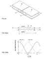
- Figs. 1A, 1B, 1C, 1D, 1E, and 1F show the relationship between a dielectric lens and a primary radiator of an antenna apparatus, and the relationship to the tilt angle of a radiation beam;
- Figs. 2A, 2B, and 2C show another relationship between a dielectric lens and a primary radiator of an antenna apparatus, and another relationship to the tilt angle of a radiation beam;
- Figs. 3A and 3B show the measurement result of the tilt angle of the radiation beam with respect to the offset of the primary radiator from the dielectric lens;
- Figs. 4A and 4B show the measurement result of the tilt angle of the radiation beam when the angle of the dielectric lens with respect to the primary radiator is varied;
- Fig. 5 is a sectional view illustrating an example of the construction of a transmission and receiving apparatus;
- Fig. 6 is a sectional view illustrating another example of the construction of the transmission and receiving apparatus;
- Fig. 7 is a plan view of the transmission and receiving apparatus;
- Fig. 8 is a schematic diagram of a transmission and receiving apparatus according to a first embodiment of the present invention;
- Figs. 9A, 9B, 9C, and 9D show the construction of a dielectric line for use in the transmission and receiving apparatus;
- Figs. 10A and 10B are a plan view and a sectional view, respectively, showing the construction of a primary vertical radiator;
- Fig. 11 shows the relationship between the primary vertical radiator and a dielectric-line apparatus;
- Fig. 12 is a partial perspective view of a directional coupler;
- Figs. 13A and 13B show the construction of the directional coupler and the relationship to the characteristics thereof;
- Fig. 14 is a diagram of the whole, including a transmission and receiving section of the transmission and receiving apparatus, according to the first embodiment of the present invention;
- Fig. 15 is a plan view illustrating the construction of a transmission and receiving apparatus according to a second embodiment of the present invention;
- Figs. 16A, 16B, and 16C show three examples of a directional coupler in a movable section of an antenna apparatus according to a third embodiment of the present invention;
- Fig. 17 shows an example of the directional coupler in the movable section of an antenna apparatus according to a fourth embodiment of the present invention;
- Fig. 18 shows the situation in which the radiation beam is tilted in the horizontal direction in a vehicle-mounted radar;
- Fig. 19 shows the situation in which the radiation beam is tilted in the horizontal direction in the vehicle-mounted radar;
- Fig. 20 shows the situation in which the radiation beam is tilted in the vertical direction in the vehicle-mounted radar;
- Fig. 21 shows the way the vehicle-mounted radar is used; and
- Fig. 22 is a block diagram illustrating the construction of the vehicle-mounted radar.
-
- The construction of an antenna apparatus and a transmission and receiving apparatus will be described below with reference to Figs. 1A, 1B, 1C, 1D, 1E, and 1F to 7.
- Figs. 1A to 1F show the positional relationship between a dielectric lens and a primary radiator, and the relationship with the directivity of a radiation beam. In Figs. 1A to 1F,
reference numeral 1 denotes a primary radiator, with adielectric lens 2 being disposed with its radiation direction as the center axis. Figs. 1A, 1B, and 1C show an example in which thedielectric lens 2 is fixed and theprimary radiator 1 is movable. As shown in Fig. 1A, when the center axis of thedielectric lens 2 coincides with the radiation direction of theprimary radiator 1, a radiation beam B is directed toward the front of thedielectric lens 2. However, when theprimary radiator 1 is displaced within the focal plane of thedielectric lens 2 as shown in Figs. 1B and 1C, the radiation beam B is directed in a direction opposite to the displacement direction. Figs. 1D, 1E, and 1F show an example in which theprimary radiator 1 is fixed and thedielectric lens 2 is movable. When the center axis of thedielectric lens 2 coincides with the radiation direction of theprimary radiator 1, a radiation beam B is directed toward the front of thedielectric lens 2. However, when thedielectric lens 2 is displaced in a direction perpendicular to the center axis thereof as shown in Figs. 1E and 1F, the radiation beam B is directed toward the displacement direction. - Figs. 2A, 2B and 2C show a case in which the angle between the dielectric lens and the primary radiator is varied to vary the direction of the radiation beam. As shown in Fig. 2A, when the radiation direction of the
primary radiator 1 is directed in the direction of the center axis of thedielectric lens 2, the radiation beam B is directed toward the front of thedielectric lens 2. However, by varying the axial direction of the dielectric lens with respect to theprimary radiator 1 as shown in Figs. 2B and 2C, the radiation beam B is directed in that direction. - Figs. 3A and 3B show the measurement result of the directional angle (tilt angle) of the radiation beam when the amount of displacement (offset) within the focal plane of the
primary radiator 1 with respect to thedielectric lens 2 is varied. Here, as thedielectric lens 2, PE (polyethylene) of a relative dielectric constant ,r=2.3 is used, the open aperture N thereof is set at 75 mm, the focal distance d thereof is set at 22.5 mm, and as theprimary radiator 1, a horn antenna is used. By varying the amount of offset of theprimary radiator 1 in a range of 0 to 5 mm as described above, the tilt angle of the radiation beam can be varied in a range of 0 to 7E. - Figs. 4A and 4B show the measurement result of the directional angle (tilt angle) of the radiation beam when the axial direction of the
dielectric lens 2 with respect to the primary radiator is varied. Here, as thedielectric lens 2, PE of a relative dielectric constant ,r=2.3 is used, the open aperture N thereof is set at 75 mm, the focal distance d thereof is set at 21.0 mm, and as theprimary radiator 1, a primary vertical radiator formed of a dielectric resonator which is excited by a non-radiative dielectric line (NRD guide) is used. By varying the angle of thedielectric lens 2 in a range of 0 to 5E as described above, the tilt angle of the radiation beam can be varied in a range of 0 to 9E. - Fig. 5 is a sectional view illustrating the construction of a transmission and receiving apparatus. In Fig. 5,
reference numeral 3 denotes a housing which houses a transmitting and receiving section, including theprimary radiator 1, with thedielectric lens 2 being mounted to the opening section (the upper part in Fig. 5). Within thehousing 3, theprimary radiator 1 is mounted via adriving section 4, which causes theprimary radiator 1 to be displaced in a planar direction perpendicular to the radiation direction. Thisdriving section 4 is formed of, for example, a linear motor or a solenoid. With this construction, as shown in Figs. 1A to 1C, the relative positional relationship between thedielectric lens 2 and theprimary radiator 1 is varied to tilt the radiation beam. - Fig. 6 is a sectional view illustrating another example of the construction of the transmission and receiving apparatus. In Fig. 6, within the
housing 3, the whole of the transmitting and receiving section, including theprimary radiator 1, is fixed, with thedielectric lens 2 being mounted onto the opening section of thehousing 3 via thedriving section 4. Thisdriving section 4, which is formed of a linear motor, a solenoid, and the like, causes thedielectric lens 2 to be displaced in a planar direction normal to the center axis thereof. As a result, as shown in Figs. 1D to 1F, the dielectric lens is displaced with respect to the primary radiator in order to tilt the radiation beam. - Also in the case where the angle of the dielectric lens with respect to the primary radiator is varied as shown in Fig. 2, basically, the construction shown in Fig. 6 may be adopted. That is, in Fig. 6, each of two of the right and left driving
sections 4 may be displaced to vary the axial direction of the dielectric lens. Further, when the angle of the primary radiator with respect to the dielectric lens is varied, basically, the construction shown in Fig. 5 may be adopted. That is, in Fig. 5, each of two of the right and left drivingsections 4 may be displaced to vary the axial direction of the primary radiator. In the above-described examples, for the sake of description, the primary radiator or the dielectric lens is displaced in directions within the plane of the paper surface, and as shown in Figs. 18 to 20, the primary radiator or the dielectric lens may be displaced in the two-dimensional direction when the radiation beam is tilted not only in the right-to-left direction but also in the up-and-down direction as in a millimetric-wave radar which detects a vehicle in the forward direction. Fig. 7 is a plan view of the transmission and receiving apparatus when viewed from the axial direction of the dielectric lens. In this case, by displacing theprimary radiator 1 relatively in the x-axis and y-axis directions with respect to the dielectric lens, the radiation beam is tilted in the x-axis and y-axis directions. - Next, the construction of an antenna apparatus and a transmission and receiving apparatus according to a first embodiment of the present invention will be described with reference to Figs. 8 to 14.
- Fig. 8 is a schematic diagram illustrating the construction of the entire transmission and receiving apparatus. In this first embodiment, by displacing the
primary radiator 1 in the right-to-left direction in the figure within thehousing 3, the radiation beam is tilted in the right-to-left direction in the figure. - Figs. 9A, 9B, 9C, and 9D are partial perspective views illustrating the construction of a dielectric line for use in the transmission and receiving apparatus according to the first embodiment of the present invention. In Figs. 9A, 9B, 9C, and 9D,
reference numerals dielectric strip 100 being sandwiched between these two conductor plates. In the examples shown in Figs. 9A and 9C, asubstrate 103, together withdielectric strips conductor plates conductor plates - Figs. 10A and 10B show the construction of a primary vertical radiator. Fig. 10A is a plan view when viewed from the radiation direction, and Fig. 10B is a sectional view of the essential portion thereof. A
dielectric strip 12 and a cylindricaldielectric resonator 11 are provided betweenconductor plates hole 43, which is coaxial with thedielectric resonator 11, being formed in theconductor plate 41. Then, aslit plate 44 having a slit formed in the conductor plate is interposed between thedielectric resonator 11 and thehole 43. As a result, in the LSM mode in which occur an electric field having components at right angles (in the x-axis direction in the figure) to the length of thedielectric strip 12 and parallel (in the y-axis direction in the figure) to theconductor plates conductor plates dielectric strip 12. Then, thedielectric strip 12 and thedielectric resonator 11 are electromagnetically coupled to each other, and an HE111 mode having electric-field components in the same direction as that of the electric field of thedielectric strip 12 occurs within thedielectric resonator 11. Then, a linearly polarized electromagnetic wave is radiated in a perpendicular direction (in the z-axis direction) via thehole 43 to theconductor plate 41. When, conversely, an electromagnetic wave enters from thehole 43, thedielectric resonator 11 excites in the HE111 mode, and the electromagnetic wave propagates to thedielectric strip 12, which is coupled to thedielectric resonator 11, in the LSM mode. - Fig. 11 shows the relationship between the primary vertical radiator and a dielectric-line apparatus comprising a dielectric line coupled to the primary radiator. The top half of Fig. 11 is a plan view of the coupled section of a
primary radiator 40 and a dielectric-line apparatus 50. However, in Fig. 11, a state in which the upper conductor plate is removed is shown. The bottom half of Fig. 11 is a sectional view illustrating the relationship between theprimary radiator 40 and thedielectric lens 2. Adielectric strip 13 is provided in the dielectric-line apparatus 50 as shown in the top half of the figure, and thedielectric strip 12 of theprimary radiator 40 is brought close to thedielectric strip 13, forming a directional coupler formed of a dielectric line in the portion surrounded by the broken line in the figure. This directional coupler using the dielectric strips 12 and 13 causes an electromagnetic wave propagated fromport # 1 to propagate toport # 4 at approximately 0 dB, that is, a 0-dB directional coupler is formed. Even if the primaryvertical radiator 40 moves in the right-to-left direction in the figure in this state, the coupling relationship of the directional coupler does not vary, and the electromagnetic wave propagated fromport # 1 is output toport # 4 always at approximately 0 dB. Conversely, the electromagnetic wave which is made to enter fromport # 4 because of the excitation of the dielectric resonator is propagated toport # 1 at approximately 0 dB. In the state shown in the figure, portions indicated by o and o' of thedielectric strip 12 correspond to a and b portions. When the primaryvertical radiator 40 is displaced at a maximum to the right in the figure, the points n and n' coincide with the a and b portions. When, conversely, the primaryvertical radiator 40 is displaced at a maximum to the left in the figure, the points p and p' coincide with the a and b portions. Even if the primaryvertical radiator 40 is displaced in this manner, since that portion of thedielectric strip 12 which is coupled to thedielectric strip 13 is a straight-line portion, these are maintained always at a fixed amount of coupling. - Fig. 12 is a partial perspective view of a directional coupler formed between the primary vertical radiator and the dielectric-line apparatus. In Fig. 12,
reference numerals conductor plates conductor plates - Figs. 13A and 13B show the directional coupler and the relationship of the power distribution ratio thereof, respectively. If the phase constant of the even mode of the coupling line formed of the
dielectric strips port # 2 to the electromagnetic wave input fromport # 1 is expressed as P2/P1 = 1 - sin2 ()$z/2), and the power ratio of the electromagnetic wave output toport # 4 to the electromagnetic wave input fromport # 1 is expressed as P4/P1 = sin2 ()$z/2). Therefore, if the relationship of ()$z/2) = nB + B/2 [n:0,1,2...] is satisfied, all of the input fromport # 1 is output toport # 4, and thus a 0-dB directional coupler is formed. - Fig. 14 shows the construction of the dielectric-line apparatus, including a transmission and receiving section, and the whole primary vertical radiator, with the upper conductor plate being removed. In Fig. 14,
reference numeral 53 denotes a circulator, in which a signal input fromport # 1 is output toport # 2, and a signal input fromport # 2 is output toport # 3. A dielectric line formed by adielectric strip 14 is connected toport # 1, and a dielectric line formed by adielectric strip 15 is connected toport # 3. Anoscillator 55 and amixer 54 are connected to the respective dielectric lines formed by thedielectric strips dielectric strip 16 which is coupled to each dielectric line to form each directional coupler is disposed between thedielectric strips dielectric strip 16. A varactor diode and a Gunn diode are provided in themixer 54 and theoscillator 55, and a dielectric line having a substrate shown in Fig. 9A or 9C interposed therein is formed to provide a circuit for applying a bias voltage to the varactor diode and the Gun diode. - With such a construction, an oscillation signal of the
oscillator 55 is propagated along the path of thedielectric strip 14, thecirculator 53, thedielectric strip 13, thedielectric strip 12, and thedielectric resonator 11, and an electromagnetic wave is radiated in the axial direction of thedielectric resonator 11. Conversely, the electromagnetic wave which enters thedielectric resonator 11 is input to themixer 54 along the path of thedielectric strip 12, thedielectric strip 13, thecirculator 53, and themixer 54. A part of the oscillation signal is provided as a local signal, together with the received signal, to themixer 54 via the two directional couplers formed of thedielectric strips mixer 54 generates a frequency component of the difference between the transmission signal and the received signal as an intermediate frequency signal. - Next, the construction of an antenna apparatus and a transmission and receiving apparatus according to a second embodiment of the present invention will be described with reference to Fig. 15. In this second embodiment, a primary vertical radiator can be moved in a two-dimensional direction. As shown in the plan view of Fig. 15, a dielectric line formed by the
dielectric strip 13 is provided in a dielectric-line apparatus 60, and a dielectric line formed by adielectric strip 17, acirculator 53, and the like are formed in the dielectric-line apparatus 50. Thedielectric strip 12 provided in theprimary radiator 40 and thedielectric strip 13 on the side of the dielectric-line apparatus 60 form one 0-dB directional coupler, and thedielectric strips primary radiator 40 is provided in such a manner as to be movable in the right-to-left direction in the figure with respect to the dielectric-line apparatus 60, and the dielectric-line apparatus 60 is provided in such a manner as to be movable in the vertical direction in the figure with respect to the dielectric-line apparatus 50. In this case, the dielectric-line apparatus 50 is fixed. This makes it possible to move the position of thedielectric resonator 11 in a two-dimensional direction in a state in which there is hardly any loss in the coupler. - Figs. 16A, 16B, and 16C are plan views showing other examples of a directional coupler in the movable section of an antenna apparatus according to a third embodiment of the present invention, with an illustration of the upper and lower conductor plates being omitted. In the example of Fig. 16A, the
dielectric strip 12 on the side which couples to thedielectric resonator 11 is formed as a straight line. In the example of Fig. 16B, thedielectric strip 13 on the side which couples to thedielectric resonator 12 is formed as a straight line. In the example of Fig. 16C, one end of thedielectric strip 12 which is coupled at its other end to thedielectric resonator 11 is kept at a fixed distance to and in parallel to themating dielectric strip 13 up to the end portion. - Fig. 17 shows an example of the construction of a directional coupler in the movable section of an antenna apparatus according to a fourth embodiment of the present invention. Although in the above-described examples a 0-dB directional coupler is formed as a directional coupler in the movable section, as shown in Fig. 17, terminaters 23 and 24 may be provided in one end of the
dielectric strips dielectric strips - Although the above-described embodiments describe a primary vertical radiator using a dielectric resonator and a dielectric line, or a horn antenna as examples of the primary radiator, in addition to these, a microstrip antenna, such as a patch antenna, may be used.
Claims (4)
- An antenna apparatus, comprising:characterized in thata dielectric lens (2); anda primary radiator (1) comprising a first dielectric line (12) serving as an input/output section, a dielectric resonator (11) which is coupled to the first dielectric line (12), and an opening section (43) from which an electromagnetic wave is radiated or is made to enter in the axial direction, wherein a second dielectric line (13) is provided close to said first dielectric line (12) in order to form a directional coupler;
the dielectric lens (2) and the primary radiator (1) are provided so that the position of the primary radiator (1) within the focal plane of the dielectric lens (2) can be changed for beam scanning, said antenna being used in a radar for transmitting and receiving an electromagnetic wave of the millimeter wave band, and
the relative positional relationship between said dielectric lens (2) and said primary radiator (1) is changed in the coupled section of the first and second dielectric lines (12, 13). - An antenna apparatus according to claim 1, wherein the amount of coupling of said directional coupler is approximately 0 dB.
- An antenna apparatus according to claim 1 or 2, wherein a transmission section, a receiving section, and a circulator (53) for separating a transmission signal and a received signal are connected to said second dielectric line (13) so that the antenna apparatus is used for both transmission and reception.
- A transmission and receiving apparatus, comprising an antenna apparatus according to one of claims 1 to 3, and a driving section (4) for changing the relative positional relationship between said dielectric lens (2) and said primary radiator (1).
Applications Claiming Priority (3)
| Application Number | Priority Date | Filing Date | Title |
|---|---|---|---|
| JP89397 | 1997-01-07 | ||
| JP00089397A JP3186622B2 (en) | 1997-01-07 | 1997-01-07 | Antenna device and transmitting / receiving device |
| JP893/97 | 1997-01-07 |
Publications (3)
| Publication Number | Publication Date |
|---|---|
| EP0852409A2 EP0852409A2 (en) | 1998-07-08 |
| EP0852409A3 EP0852409A3 (en) | 1998-12-02 |
| EP0852409B1 true EP0852409B1 (en) | 2002-07-03 |
Family
ID=11486369
Family Applications (1)
| Application Number | Title | Priority Date | Filing Date |
|---|---|---|---|
| EP98100074A Expired - Lifetime EP0852409B1 (en) | 1997-01-07 | 1998-01-05 | Antenna apparatus and transmission and receiving apparatus using same |
Country Status (6)
| Country | Link |
|---|---|
| US (3) | US6362795B2 (en) |
| EP (1) | EP0852409B1 (en) |
| JP (1) | JP3186622B2 (en) |
| KR (1) | KR100294612B1 (en) |
| CN (1) | CN1124661C (en) |
| DE (1) | DE69806276T2 (en) |
Families Citing this family (57)
| Publication number | Priority date | Publication date | Assignee | Title |
|---|---|---|---|---|
| JP3186622B2 (en) * | 1997-01-07 | 2001-07-11 | 株式会社村田製作所 | Antenna device and transmitting / receiving device |
| DE19710811B4 (en) * | 1997-03-15 | 2006-06-01 | Robert Bosch Gmbh | Device for directionally emitting and / or picking up electromagnetic waves |
| JP3548820B2 (en) * | 1998-12-24 | 2004-07-28 | 株式会社村田製作所 | Antenna device and transmission / reception module |
| EP1014484B1 (en) | 1998-12-24 | 2003-05-02 | Murata Manufacturing Co., Ltd. | Antenna with displaceable radiator and dielectric lens |
| US6396448B1 (en) * | 1999-08-17 | 2002-05-28 | Ems Technologies, Inc. | Scanning directional antenna with lens and reflector assembly |
| JP2001127524A (en) * | 1999-10-28 | 2001-05-11 | Kyocera Corp | Beam scan antenna |
| DE19961774A1 (en) * | 1999-12-21 | 2001-07-12 | Bosch Gmbh Robert | Device for setting a directional beam system |
| JP3788217B2 (en) | 2000-09-08 | 2006-06-21 | 株式会社村田製作所 | Directional coupler, antenna device, and radar device |
| JP2002111359A (en) * | 2000-09-27 | 2002-04-12 | Murata Mfg Co Ltd | Antenna device, communication device and radar device |
| JP3473576B2 (en) * | 2000-12-05 | 2003-12-08 | 株式会社村田製作所 | Antenna device and transmitting / receiving device |
| JP2002246832A (en) * | 2001-02-15 | 2002-08-30 | Matsushita Electric Ind Co Ltd | Communication apparatus |
| JP2002257932A (en) * | 2001-03-06 | 2002-09-11 | Nippon Telegr & Teleph Corp <Ntt> | Imaging device of type detecting reflected electromagnetic wave |
| JP4535641B2 (en) * | 2001-05-30 | 2010-09-01 | 京セラ株式会社 | Primary radiator and phase shifter and beam scanning antenna |
| JP2003215233A (en) * | 2002-01-24 | 2003-07-30 | Murata Mfg Co Ltd | Radar head module |
| WO2004088793A1 (en) * | 2003-03-31 | 2004-10-14 | Bae Systems Plc | Low-profile lens antenna |
| JP4012125B2 (en) * | 2003-06-25 | 2007-11-21 | キヤノン株式会社 | Electromagnetic wave control device and sensing system |
| KR100787988B1 (en) | 2003-06-25 | 2007-12-24 | 캐논 가부시끼가이샤 | High frequency electrical signal control device and sensing system |
| US8624775B2 (en) | 2009-04-23 | 2014-01-07 | Mitsubishi Electric Corporation | Radar apparatus and antenna device |
| KR101136519B1 (en) * | 2010-03-09 | 2012-04-17 | (주)파트론 | Intergrated coupler-circulator and power amplifier compring the same |
| KR101767293B1 (en) | 2010-07-29 | 2017-08-10 | 스카이워크스 솔루션즈, 인코포레이티드 | Reducing coupling coefficient variation by using capacitors |
| GB2492081B (en) * | 2011-06-20 | 2014-11-19 | Canon Kk | Antenna lens including holes and different permittivity layers |
| CN103259078B (en) * | 2012-02-21 | 2016-06-29 | 华硕电脑股份有限公司 | Wireless communication apparatus |
| DE102012202913A1 (en) * | 2012-02-27 | 2013-08-29 | Robert Bosch Gmbh | radar sensor |
| RU2533058C2 (en) * | 2012-05-15 | 2014-11-20 | Евгений Вячеславович Комраков | Versatile device for transmission of radiation from source to object |
| US9515388B2 (en) | 2012-10-17 | 2016-12-06 | Samsung Electronics Co., Ltd. | Controlled lens antenna apparatus and system |
| DE102013208719A1 (en) * | 2013-05-13 | 2014-11-13 | Robert Bosch Gmbh | Radar sensor and method for operating a radar sensor |
| JP2016046577A (en) * | 2014-08-20 | 2016-04-04 | 横河電子機器株式会社 | Antenna device |
| DE102014013003A1 (en) * | 2014-08-29 | 2016-03-03 | Audi Ag | Radar sensor, in particular for a motor vehicle, and motor vehicle |
| CN104793188A (en) * | 2015-04-29 | 2015-07-22 | 芜湖航飞科技股份有限公司 | Vehicle-mounted millimeter-wave anti-collision radar antenna system |
| AT517407B1 (en) * | 2015-06-19 | 2017-08-15 | Zkw Group Gmbh | Laser unit with collimator adjustment device |
| US11367959B2 (en) | 2015-10-28 | 2022-06-21 | Rogers Corporation | Broadband multiple layer dielectric resonator antenna and method of making the same |
| US10355361B2 (en) | 2015-10-28 | 2019-07-16 | Rogers Corporation | Dielectric resonator antenna and method of making the same |
| US10374315B2 (en) | 2015-10-28 | 2019-08-06 | Rogers Corporation | Broadband multiple layer dielectric resonator antenna and method of making the same |
| US10476164B2 (en) | 2015-10-28 | 2019-11-12 | Rogers Corporation | Broadband multiple layer dielectric resonator antenna and method of making the same |
| US10601137B2 (en) | 2015-10-28 | 2020-03-24 | Rogers Corporation | Broadband multiple layer dielectric resonator antenna and method of making the same |
| DE102015015034B4 (en) * | 2015-11-23 | 2023-04-27 | Baumer Electric Ag | sensor arrangement |
| EP3414793B1 (en) * | 2016-02-12 | 2020-05-20 | Aeronet Global Communications Labs Dac | Antenna system comprising dielectric lenses and method for aerial vehicles |
| JP6683539B2 (en) * | 2016-05-25 | 2020-04-22 | 日立オートモティブシステムズ株式会社 | Antenna, sensor and in-vehicle system |
| US11283189B2 (en) | 2017-05-02 | 2022-03-22 | Rogers Corporation | Connected dielectric resonator antenna array and method of making the same |
| US11876295B2 (en) | 2017-05-02 | 2024-01-16 | Rogers Corporation | Electromagnetic reflector for use in a dielectric resonator antenna system |
| KR102381621B1 (en) * | 2017-05-18 | 2022-04-01 | 삼성전자 주식회사 | Glass structure including lens and receiver including lens |
| JP6838250B2 (en) * | 2017-06-05 | 2021-03-03 | 日立Astemo株式会社 | Antennas, array antennas, radar devices and in-vehicle systems |
| GB2575946B (en) | 2017-06-07 | 2022-12-14 | Rogers Corp | Dielectric resonator antenna system |
| DE102017219372A1 (en) * | 2017-10-27 | 2019-05-02 | Robert Bosch Gmbh | Radar sensor with several main beam directions |
| CN109839631B (en) * | 2017-11-27 | 2023-09-19 | 松下知识产权经营株式会社 | Radar apparatus |
| KR102531003B1 (en) * | 2017-12-19 | 2023-05-10 | 삼성전자 주식회사 | Beam forming antenna module including lens |
| US11616302B2 (en) | 2018-01-15 | 2023-03-28 | Rogers Corporation | Dielectric resonator antenna having first and second dielectric portions |
| US10892544B2 (en) | 2018-01-15 | 2021-01-12 | Rogers Corporation | Dielectric resonator antenna having first and second dielectric portions |
| US10910722B2 (en) | 2018-01-15 | 2021-02-02 | Rogers Corporation | Dielectric resonator antenna having first and second dielectric portions |
| EP3534173B1 (en) * | 2018-02-28 | 2023-08-02 | Baumer Electric AG | Housing unit for a radar sensor |
| US11552390B2 (en) | 2018-09-11 | 2023-01-10 | Rogers Corporation | Dielectric resonator antenna system |
| US11031697B2 (en) | 2018-11-29 | 2021-06-08 | Rogers Corporation | Electromagnetic device |
| GB2594171A (en) | 2018-12-04 | 2021-10-20 | Rogers Corp | Dielectric electromagnetic structure and method of making the same |
| US11482790B2 (en) | 2020-04-08 | 2022-10-25 | Rogers Corporation | Dielectric lens and electromagnetic device with same |
| EP4043841A1 (en) * | 2021-02-12 | 2022-08-17 | Rosemount Tank Radar AB | Radar level gauge with elastic system |
| US20230006346A1 (en) * | 2021-05-27 | 2023-01-05 | Tata Consultancy Services Limited | Computer controlled electromechanical mmw frequency antenna scanning system and beam steering thereof |
| US11888580B2 (en) * | 2022-03-28 | 2024-01-30 | United States Of America As Represented By The Secretary Of The Navy | Near-omnidirectional optical communication system |
Family Cites Families (19)
| Publication number | Priority date | Publication date | Assignee | Title |
|---|---|---|---|---|
| US2887684A (en) * | 1954-02-01 | 1959-05-19 | Hughes Aircraft Co | Dielectric lens for conical scanning |
| US3761935A (en) * | 1972-03-06 | 1973-09-25 | Republic Electronic Ind Inc | Wide angle microwave scanning antenna array with distortion correction means |
| US3833909A (en) * | 1973-05-07 | 1974-09-03 | Sperry Rand Corp | Compact wide-angle scanning antenna system |
| US4531129A (en) * | 1983-03-01 | 1985-07-23 | Cubic Corporation | Multiple-feed luneberg lens scanning antenna system |
| US4642651A (en) * | 1984-09-24 | 1987-02-10 | The United States Of America As Represented By The Secretary Of The Army | Dual lens antenna with mechanical and electrical beam scanning |
| US4566321A (en) * | 1985-01-18 | 1986-01-28 | Transamerica Delaval Inc. | Microwave tank-contents level measuring assembly with lens-obturated wall-opening |
| US4794398A (en) * | 1986-10-01 | 1988-12-27 | United Technologies Corporation | Multimode, multispectral scanning and detection |
| GB8711271D0 (en) * | 1987-05-13 | 1987-06-17 | British Broadcasting Corp | Microwave lens & array antenna |
| GB9102585D0 (en) * | 1991-02-06 | 1991-03-27 | Marconi Gec Ltd | Radar system |
| JP3336733B2 (en) * | 1994-04-07 | 2002-10-21 | 株式会社村田製作所 | Communication module for transportation |
| DE4412770A1 (en) * | 1994-04-13 | 1995-10-19 | Siemens Ag | Microwave lens aerial for car distance warning radar |
| JP3042364B2 (en) * | 1995-05-19 | 2000-05-15 | 株式会社村田製作所 | Dielectric antenna |
| DE19530065A1 (en) * | 1995-07-01 | 1997-01-09 | Bosch Gmbh Robert | Monostatic FMCW radar sensor |
| DE19642810C1 (en) | 1996-10-17 | 1998-04-02 | Bosch Gmbh Robert | Directional radar system for anticollision and vehicle speed measurement |
| JPH10145129A (en) * | 1996-11-01 | 1998-05-29 | Honda Motor Co Ltd | Antenna equipment |
| JP3186622B2 (en) * | 1997-01-07 | 2001-07-11 | 株式会社村田製作所 | Antenna device and transmitting / receiving device |
| EP0896749B1 (en) * | 1997-02-06 | 2003-01-22 | Robert Bosch Gmbh | Microwave antenna array for a motor vehicle radar system |
| EP1014484B1 (en) * | 1998-12-24 | 2003-05-02 | Murata Manufacturing Co., Ltd. | Antenna with displaceable radiator and dielectric lens |
| US6344829B1 (en) * | 2000-05-11 | 2002-02-05 | Agilent Technologies, Inc. | High-isolation, common focus, transmit-receive antenna set |
-
1997
- 1997-01-07 JP JP00089397A patent/JP3186622B2/en not_active Expired - Fee Related
-
1998
- 1998-01-05 DE DE69806276T patent/DE69806276T2/en not_active Expired - Lifetime
- 1998-01-05 EP EP98100074A patent/EP0852409B1/en not_active Expired - Lifetime
- 1998-01-07 CN CN98103945A patent/CN1124661C/en not_active Expired - Fee Related
- 1998-01-07 US US09/003,662 patent/US6362795B2/en not_active Expired - Lifetime
- 1998-01-07 KR KR1019980000191A patent/KR100294612B1/en not_active IP Right Cessation
-
2001
- 2001-09-20 US US09/960,459 patent/US6563477B2/en not_active Expired - Fee Related
-
2003
- 2003-03-12 US US10/385,842 patent/US20030214457A1/en not_active Abandoned
Also Published As
| Publication number | Publication date |
|---|---|
| DE69806276T2 (en) | 2002-11-07 |
| US20010013842A1 (en) | 2001-08-16 |
| EP0852409A3 (en) | 1998-12-02 |
| US6563477B2 (en) | 2003-05-13 |
| US6362795B2 (en) | 2002-03-26 |
| JP3186622B2 (en) | 2001-07-11 |
| KR100294612B1 (en) | 2001-07-12 |
| CN1124661C (en) | 2003-10-15 |
| US20030214457A1 (en) | 2003-11-20 |
| KR19980070385A (en) | 1998-10-26 |
| CN1188995A (en) | 1998-07-29 |
| DE69806276D1 (en) | 2002-08-08 |
| JPH10200331A (en) | 1998-07-31 |
| US20020018022A1 (en) | 2002-02-14 |
| EP0852409A2 (en) | 1998-07-08 |
Similar Documents
| Publication | Publication Date | Title |
|---|---|---|
| EP0852409B1 (en) | Antenna apparatus and transmission and receiving apparatus using same | |
| JP3473576B2 (en) | Antenna device and transmitting / receiving device | |
| US6433741B2 (en) | Directional coupler, antenna device, and transmitting-receiving device | |
| JP3287309B2 (en) | Directional coupler, antenna device, and transmission / reception device | |
| EP1195849B1 (en) | Antenna device, communication apparatus and radar module | |
| EP0871239B1 (en) | Antenna device and radar module | |
| JP3163981B2 (en) | Transceiver | |
| EP0838693B1 (en) | Antenna-shared distributor and transmission and receiving apparatus using same | |
| JP3731354B2 (en) | Antenna device and transmitting / receiving device | |
| EP0920068B1 (en) | Dielectric line switch and antenna device | |
| JP2000082904A (en) | Directional coupler, antenna device and transmitter- receiver |
Legal Events
| Date | Code | Title | Description |
|---|---|---|---|
| PUAI | Public reference made under article 153(3) epc to a published international application that has entered the european phase |
Free format text: ORIGINAL CODE: 0009012 |
|
| 17P | Request for examination filed |
Effective date: 19980105 |
|
| AK | Designated contracting states |
Kind code of ref document: A2 Designated state(s): DE FR GB |
|
| AX | Request for extension of the european patent |
Free format text: AL;LT;LV;MK;RO;SI |
|
| PUAL | Search report despatched |
Free format text: ORIGINAL CODE: 0009013 |
|
| AK | Designated contracting states |
Kind code of ref document: A3 Designated state(s): AT BE CH DE DK ES FI FR GB GR IE IT LI LU MC NL PT SE |
|
| AX | Request for extension of the european patent |
Free format text: AL;LT;LV;MK;RO;SI |
|
| AKX | Designation fees paid |
Free format text: DE FR GB |
|
| 17Q | First examination report despatched |
Effective date: 19991227 |
|
| GRAG | Despatch of communication of intention to grant |
Free format text: ORIGINAL CODE: EPIDOS AGRA |
|
| GRAG | Despatch of communication of intention to grant |
Free format text: ORIGINAL CODE: EPIDOS AGRA |
|
| GRAG | Despatch of communication of intention to grant |
Free format text: ORIGINAL CODE: EPIDOS AGRA |
|
| GRAH | Despatch of communication of intention to grant a patent |
Free format text: ORIGINAL CODE: EPIDOS IGRA |
|
| GRAH | Despatch of communication of intention to grant a patent |
Free format text: ORIGINAL CODE: EPIDOS IGRA |
|
| GRAA | (expected) grant |
Free format text: ORIGINAL CODE: 0009210 |
|
| AK | Designated contracting states |
Kind code of ref document: B1 Designated state(s): DE FR GB |
|
| REF | Corresponds to: |
Ref document number: 69806276 Country of ref document: DE Date of ref document: 20020808 |
|
| ET | Fr: translation filed | ||
| PLBE | No opposition filed within time limit |
Free format text: ORIGINAL CODE: 0009261 |
|
| STAA | Information on the status of an ep patent application or granted ep patent |
Free format text: STATUS: NO OPPOSITION FILED WITHIN TIME LIMIT |
|
| 26N | No opposition filed |
Effective date: 20030404 |
|
| PGFP | Annual fee paid to national office [announced via postgrant information from national office to epo] |
Ref country code: FR Payment date: 20130204 Year of fee payment: 16 Ref country code: GB Payment date: 20130102 Year of fee payment: 16 Ref country code: DE Payment date: 20130103 Year of fee payment: 16 |
|
| REG | Reference to a national code |
Ref country code: DE Ref legal event code: R119 Ref document number: 69806276 Country of ref document: DE |
|
| GBPC | Gb: european patent ceased through non-payment of renewal fee |
Effective date: 20140105 |
|
| PG25 | Lapsed in a contracting state [announced via postgrant information from national office to epo] |
Ref country code: DE Free format text: LAPSE BECAUSE OF NON-PAYMENT OF DUE FEES Effective date: 20140801 |
|
| REG | Reference to a national code |
Ref country code: FR Ref legal event code: ST Effective date: 20140930 |
|
| REG | Reference to a national code |
Ref country code: DE Ref legal event code: R119 Ref document number: 69806276 Country of ref document: DE Effective date: 20140801 |
|
| PG25 | Lapsed in a contracting state [announced via postgrant information from national office to epo] |
Ref country code: FR Free format text: LAPSE BECAUSE OF NON-PAYMENT OF DUE FEES Effective date: 20140131 Ref country code: GB Free format text: LAPSE BECAUSE OF NON-PAYMENT OF DUE FEES Effective date: 20140105 |