EP0852017B1 - Positionsbestimmung der quelle eines unbekannten signales - Google Patents
Positionsbestimmung der quelle eines unbekannten signales Download PDFInfo
- Publication number
- EP0852017B1 EP0852017B1 EP95933479A EP95933479A EP0852017B1 EP 0852017 B1 EP0852017 B1 EP 0852017B1 EP 95933479 A EP95933479 A EP 95933479A EP 95933479 A EP95933479 A EP 95933479A EP 0852017 B1 EP0852017 B1 EP 0852017B1
- Authority
- EP
- European Patent Office
- Prior art keywords
- unknown
- signal
- signals
- frequency
- dfo
- Prior art date
- Legal status (The legal status is an assumption and is not a legal conclusion. Google has not performed a legal analysis and makes no representation as to the accuracy of the status listed.)
- Expired - Lifetime
Links
Images


Classifications
-
- G—PHYSICS
- G01—MEASURING; TESTING
- G01S—RADIO DIRECTION-FINDING; RADIO NAVIGATION; DETERMINING DISTANCE OR VELOCITY BY USE OF RADIO WAVES; LOCATING OR PRESENCE-DETECTING BY USE OF THE REFLECTION OR RERADIATION OF RADIO WAVES; ANALOGOUS ARRANGEMENTS USING OTHER WAVES
- G01S1/00—Beacons or beacon systems transmitting signals having a characteristic or characteristics capable of being detected by non-directional receivers and defining directions, positions, or position lines fixed relatively to the beacon transmitters; Receivers co-operating therewith
- G01S1/02—Beacons or beacon systems transmitting signals having a characteristic or characteristics capable of being detected by non-directional receivers and defining directions, positions, or position lines fixed relatively to the beacon transmitters; Receivers co-operating therewith using radio waves
- G01S1/022—Means for monitoring or calibrating
- G01S1/026—Means for monitoring or calibrating of associated receivers
-
- G—PHYSICS
- G01—MEASURING; TESTING
- G01S—RADIO DIRECTION-FINDING; RADIO NAVIGATION; DETERMINING DISTANCE OR VELOCITY BY USE OF RADIO WAVES; LOCATING OR PRESENCE-DETECTING BY USE OF THE REFLECTION OR RERADIATION OF RADIO WAVES; ANALOGOUS ARRANGEMENTS USING OTHER WAVES
- G01S19/00—Satellite radio beacon positioning systems; Determining position, velocity or attitude using signals transmitted by such systems
- G01S19/01—Satellite radio beacon positioning systems transmitting time-stamped messages, e.g. GPS [Global Positioning System], GLONASS [Global Orbiting Navigation Satellite System] or GALILEO
- G01S19/13—Receivers
- G01S19/20—Integrity monitoring, fault detection or fault isolation of space segment
-
- G—PHYSICS
- G01—MEASURING; TESTING
- G01S—RADIO DIRECTION-FINDING; RADIO NAVIGATION; DETERMINING DISTANCE OR VELOCITY BY USE OF RADIO WAVES; LOCATING OR PRESENCE-DETECTING BY USE OF THE REFLECTION OR RERADIATION OF RADIO WAVES; ANALOGOUS ARRANGEMENTS USING OTHER WAVES
- G01S5/00—Position-fixing by co-ordinating two or more direction or position line determinations; Position-fixing by co-ordinating two or more distance determinations
- G01S5/02—Position-fixing by co-ordinating two or more direction or position line determinations; Position-fixing by co-ordinating two or more distance determinations using radio waves
- G01S5/06—Position of source determined by co-ordinating a plurality of position lines defined by path-difference measurements
Definitions
- This invention relates to a method and apparatus for locating the source of an unknown signal received by a plurality of signal relays.
- Prior art location systems which employ a technique based on determination of the time difference of arrival (TDOA) of two signals from the source to be located, ie an unknown transmitter.
- TDOA time difference of arrival
- a signal from the transmitter is relayed to a ground-based receiving station along two independent signal paths by a respective earth-orbiting satellite in each path.
- Each satellite incorporates a transponder system which accepts a signal (uplink) from a ground transmitter at one frequency and returns a frequency-shifted (downlink) signal to a ground receiver with the aid of a turnround oscillator.
- the signal paths are of unequal length, because the two satellites are in different positions. In consequence, the signal arrival time at the receiving station associated with one path is different to that associated with the other.
- the positions of the two satellites and the receiving station are known, and consequently the time difference of arrival - the TDOA - of the signal over the two different paths provides information on the location of the unknown transmitter.
- the locus of points of constant TDOA defines a curve on the earth referred to as a line of position (LOP).
- LOP line of position
- An unknown ground-based transmitter giving rise to a specific value of TDOA is located at some point on the LOP associated with that value.
- the geometrical relationship between the satellites together with signal propagation delay in satellite transponders and receiving station equipment, must be known in order to determine the correct value of TDOA.
- US Patent No 5,008,679 discloses a transmitter location system incorporating two relay satellites as previously mentioned, the system employing both the TDOA of signals from an unknown transmitter and what is referred to as their frequency difference of arrival (FDOA).
- FDOA occurs because the relay satellites are in motion relative to the earth and to one another, and in each case the motion introduces a Doppler shift into the downlink signal frequency.
- the two satellites' Doppler shifts differ, and this produces a frequency difference or FDOA between signals arriving at the receiving station from respective satellites.
- an FDOA measurement defines a line of position (LOP) upon which the unknown transmitter lies.
- the TDOA and FDOA lines of position generally differ, and their intersection provides the location of the unknown transmitter.
- the present invention provides a method of locating the source of an unknown signal received by a plurality of signal relays, the method including the steps of:-
- the invention provides the advantage that it does not require the positions and velocities of the satellites to be known with the degree of accuracy required in the prior art, and it can be used with satellites which have an orbital inclination of up to at least 3 degrees.
- the invention does not require the degree of relay or receiver phase stability required in the prior art. It does not require receivers which are located geographically together, which have common time and frequency references and -which employ phase-locked frequency downconversion using a common precision frequency standard.
- the invention is also able to perform location of an unknown signal source in the presence of other unwanted signals.
- Processing in Step (c) of the invention is preferably carried out in respect of signals received by each receiver by downconverting the unknown signal and the reference signal to intermediate frequency (IF) signals with predetermined bandwidths and obtaining digital samples thereof with sample timing and frequency downconversion controlled in accordance with a precise frequency and timing standard.
- the unknown and reference signals are preferably arranged to have like IF bandwidths not greater than 4 MHz.
- the IF bandwidth is preferably set to be as close as possible to the bandwidth of the unknown signal, to which the reference signal bandwidth is also preferably matched.
- the IF bandwidth is preferably lower than 100 kHz, eg as low as 10 kHz. This yields improved accuracy in DFO processing.
- cross ambiguity function processing in Step (d) of the invention includes the step of producing complex data from real data by a Hilbert transform procedure. This makes it unnecessary to produce in-phase and quadrature unknown and reference signals for such processing.
- Cross ambiguity function processing in Step (d) of the invention preferably also determines reference signal DTO and includes the steps of processing the reference signal as follows:-
- Measurement of the reference signal DTO by cross ambiguity function processing leads to improved accuracy of unknown source location.
- Processing in Step (d) of the invention may include determining the reference signal DFO by a method including the steps of:-
- Processing in Step (d) of the invention may include determining the unknown signal DTO by the steps of:-
- Processing in Step (d) of the invention may include determining the unknown signal DFO and may include a stage comprising processing reference signals and incorporating the steps of:-
- Processing in Step (d) of the invention may include determining the unknown signal DFO and may include a further stage comprising processing the unknown signal and incorporating the steps of:-
- the position of the unknown source is preferably calculated by a method based on:-
- the location derived for the unknown source in Step (c) may be a first value thereof, and one or more improved values thereof may be derived by back substitution of the first value in the Taylor expansion analysis and iteration of the derivation of the location of the unknown source until convergence is obtained.
- the derivation of the location of the unknown source may be refined by the steps of:-
- the differences between the calculated and measured values of the unknown signal DSR and DSRR are related to the longitude and latitude errors in the position of the unknown source by two linear equations.
- the longitude and latitude errors are preferably determined by solving these equations.
- the reference signal may be a communications signal obtainable from the signal relays, or alternatively it may be obtained from transmitters producing signals in phase coherence with one another, the transmitters being directed to respective signal relays.
- the processed reference signals and processed unknown signals are preferably stored prior to cross ambiguity function processing.
- the present invention provides an apparatus for locating the source of an unknown signal received by a plurality of signal relays, the apparatus including:-
- the apparatus of the invention may be arranged to offset received signals in time and/or frequency as appropriate in accordance with values obtained for DTO and/or DFO as the case may be and to obtain further values thereof from such offset signals. It may include reference signal transmitting means arranged to transmit to the signal relays reference signals of substantially equal intensity, and these signals may incorporate modulated and unmodulated carrier wave components. It may also include means for storing the processed reference signals and processed unknown signals prior to cross ambiguity function processing.
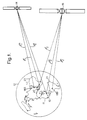
- an unknown transmitter 10 located in the United States of America 11 is shown on the surface of the Earth 12, the northern hemisphere of which is illustrated with the North Pole (not shown) located centrally.
- the unknown transmitter 10 has a main radiation intensity lobe (not shown) directed to a first satellite 14 in a geosynchronous orbit. It transmits a signal which propagates to that satellite along a first uplink path l 1 u and produces interference with unknown signals using the satellite.
- the unknown signal frequency is determined by spectrum analysis equipment which routinely monitors the unknown channels of the satellite.
- a typical communications satellite operating at Ku band (11 - 14 GHz) has 16 channels each 36 MHz wide and each capable of carrying 100 communications signals.
- the transmitter 10 also has a radiative sidelobe (not shown) directed to a second satellite 16 in a geosynchronous orbit, to which its signal propagates along a second uplink path l 2 u .
- the superscript "u" to path references l 1 u and l 2 u denotes that they originate at the unknown transmitter 10.
- the first satellite 14 receives the signal from the unknown transmitter 10 and retransmits it along a first downlink path l 1 m to a first Earth-based ground station or receiver 18A directed at that satellite and located in Israel.
- the second satellite 16 also receives the unknown transmitter signal and retransmits it along a second downlink path l 2 m to a second Earth-based receiver 18B located in South America 21.
- m denotes a path to an Earth-based receiver monitoring a satellite.
- the Earth-based receivers 18A and 18B will be referred to by the reference 18 to indicated either or both without differentiation, and as 18A or 18B as appropriate when being specific. A similar convention will be adopted for other elements with suffixes A and B to be described later.
- the total signal propagation path length from the transmitter 10 to the first receiver 18A is equal to the sum of the lengths of the paths l 1 u and l 1 m
- that from the transmitter 10 to the second receiver 18B is equal to the sum of the lengths of the paths l 2 u and l 2 m .
- a reference transmitter 22 at a known geographical position in Africa 23 transmits a reference signal along third and fourth uplink paths l 1 r and l 2 r to the first and second satellites 14 and 16 respectively; here the superscript "r" denotes transmission from the reference transmitter 22.
- the reference transmitter 22 is selected from those using the communications channel associated with one of the satellites 14 and 16.
- the satellites 14 and 16 retransmit the reference signal to the receivers 18 along the downlink paths l 1 m and l 2 m respectively.
- a transmitter location system of the invention is shown in schematic form and is indicated generally by 30.
- the unknown transmitter 10, reference transmitter 22 and receivers 18 are indicated by antenna symbols.
- the satellites 14 and 16 are indicated by rectangles.
- the receivers 18A and 18B are connected respectively to first and second acquisition systems 32A and 32B, each of which processes the unknown and reference signals in separate channels to be described in more detail later.
- the acquisition systems 32 are connected to a central control and processing computer (not shown) at a remote processing site 34 by respective modem data links 36A and 36B.
- Each comprises a container 50 on which is mounted a receive (uplink) antenna 52 and a transmit (downlink) antenna 54.
- the receive antenna 52 is connected to a low noise amplifier 56, which is in turn connected to a mixer 58 receiving a local oscillator input from a frequency turnround oscillator 60.
- the local oscillator frequency is 1.5 GHz for both satellites 14 and 16.
- the mixer 58 consequently produces a frequency downshift of 1.5 GHz.
- Output from the mixer 58 passes to a bandpass filter 62 and thereafter to a power amplifier 64 supplying a signal feed to the transmit antenna 54.
- Each acquisition system comprises a Global Positioning System (GPS) receiver 100 with an antenna 102 linking it to one or more GPS satellites (not shown) for supply of timing signals.
- GPS Global Positioning System
- the GPS consists of a number of satellites deployed in space and from which such signals are available.
- the GPS receiver 100 has a control input 104 together with outputs 106 and 108 for timing (t) and frequency (fr) signals respectively.
- the output 106 in fact represents two outputs each connected to a respective channel of the acquisition system 32 to be described later.
- the timing and frequency signals associated with the two receivers 18A and 18B are very similar but not necessarily identical, and are respectively t A and fr A , t B and fr B . This is because the unknown and reference transmitters may be located so far apart on the surface of the Earth that they have access to differing parts of the GPS. In consequence, signals in the receiver 18A are not in phase coherence with signals in the receiver 18B, and it is an advantage of the invention that it does not require such coherence.
- the control input 104 of the GPS receiver 100 is connected to a local host computer 105 which supplies control signals to it.
- the frequency signal fr is 5MHz.
- the timing signal t controls signal sampling in the procedure of locating an unknown transmitter, as will be described in more detail later.
- the computer 105 sends an instruction to the control input 104 indicating a start time; when the GPS indicates that this time has occurred the GPS receiver 100 initiates generation of the timing signal as a series of pulses in which adjacent pulses have a constant time difference At.
- the timing interval At is the same at both receivers 18A and 18B.
- the computer 105 obtains the time of any signal sample taken in response to the timing signal from t 0 + j ⁇ t, where t 0 is the start time and j is the sample number.
- Output signals from the receiver 18 pass to a low noise amplifier 110 and thence to a mixer 112, which receives a local oscillator input signal from an oscillator 114.
- the oscillator 114 is connected at 116 to the GPS receiver output 108, and is phase locked to the frequency fr.
- Output signals from the mixer 112 pass to two channels 120U and 120R for the unknown and reference signals respectively.
- These channels have like components which are like referenced with suffixes U or R to indicate the relevant channel in each case.
- the channels and their components will be referred to without the U or R suffix to indicate either or both without differentiation, and with the relevant suffix when required to be specific.
- signals from the mixer 112 pass to a tunable pre-select filter 122 and thence to a mixer 124, which receives a local oscillator input signal at a frequency of 698.6 MHz from an oscillator 126.
- the oscillator 126 is connected at 128 to the output 108 of the GPS receiver, and is phase locked to the latter's frequency fr.
- the centre frequency and bandwidth of the pre-select filter 122 and the frequency of the oscillator 126 are tunable under control of the local host computer 105.
- the mixer output signals pass to a post-select filter 130 having a fixed centre frequency and tunable bandwidth under control of the local host computer and thence to a variable gain amplifier 132, from which in turn output signals pass to an analogue to digital converter (ADC) 134.
- the ADC 134 is a high speed, high stability, 8-bit device. It has a timing input 136 connected to the GPS receiver output 106, from which it receives the timing signal t. On receipt of each pulse of the timing signal, the ADC 134 produces a digitised sample of the output signal from the variable gain amplifier 132. The signal sampling rate is a minimum of twice the bandwidth of the output signal and under control of the local host computer.
- the ADC 134 is connected to a memory 137.
- the memories 136U and 136R in the unknown and reference channels 120U and 120R respectively are both connected to the local host computer 105, which is in turn connected to an archive store 140, to the data link 36 as aforesaid, to the GPS receiver control input 104 by a connection 142, and to the GPS receiver output 106 by a connection 144.
- the site 34 incorporates a central control and processing computer 150 connected to data links 36 and to a third GPS receiver 152 having an antenna 154 communicating with the GPS system.
- the computer 150 is also connected to a DSP unit 156 and an archive store 158.
- the transmitter location system 30 operates as follows.
- the unknown transmitter 10 transmits a signal producing interference with signals in a communications channel of the first satellite 14.
- the unknown signal frequency is determined by spectrum analysis equipment monitoring the satellite communications channels.
- the unknown signal propagates to the satellites 14 and 16, where it is frequency downshifted by 1.5 GHz by the mixers 58 and retransmitted to the first and second receivers 18A and 18B respectively.
- a reference signal is then selected by human intervention. It is any signal which is present in a communications channel of the first satellite 14, which originates at a transmitter having a sidelobe directed at the second satellite 16, and which preferably has a similar bandwidth to that of the unknown signal as determined from monitoring the satellite 14 downlink.
- a typical unknown signal is transmitted with a centre frequency of 14.005 GHz and comprises a 128 kb/s data signal. This signal is downshifted in frequency to 12.505 GHz by the satellite turnround oscillator 60.
- An adjacent signal is selected as a reference by monitoring the satellite 14 downlink spectrum, such as a 256 kb/s data signal identified in the channel some 10 MHz higher in frequency than the unknown signal. Such a reference signal would have a frequency of 12.515 GHz corresponding to a transmitter frequency of 14.015 GHz.
- the reference signal is relayed by the satellites 14 and 16 to respective receivers 18.
- the signal-to-noise ratio at the first satellite 14, which is the target satellite for the main lobe of the unknown transmitter 10, is likely to be significantly greater than unity, and has typical values of 5 to 15dB.
- the second satellite 16 is likely to be associated with signals having a very low signal-to-noise ratio, because it only receives low power signals from the a sidelobe of the unknown transmitter 10. Such low signal levels are not detectable by conventional means, and it is necessary to use a signal correlation technique to be described later.
- the unknown and reference signals are amplified at 110 and mixed at 112 with a local oscillator frequency of 11.805 GHz.
- the local oscillator frequency is tuned by the respective local host computers so that the difference between each of them and the relevant unknown or reference frequency is close to a predetermined intermediate frequency (IF) of 700 MHz.
- IF intermediate frequency
- Mixing in the mixers 112 then converts the unknown and reference signals to IF signals which pass to respective pre-select filters 122U and 122R.
- the pre-select filters 122 have bandwidths tunable by means of the local host computer.
- the unknown channel pre-select filter 122U is tuned to have a passband centred on the unknown signal IF.
- the unknown channel post-select filter 130U sets the bandwidth of the downconverted signal. A wide bandwidth reduces errors in measuring time up to a point where other errors become more important, and this sets the 4MHz limit.
- the reference filter 122R is tuned to have a passband centred on the reference signal IF.
- the unknown and reference channel filters 122 have passbands and frequency selectivity appropriate for the unknown channel filter 122U to reject the reference signal and the reference channel filter 122R to reject the unknown signal.
- the unknown and reference IF signals are downconverted in mixers 124 to a lower intermediate frequency (LIF).
- LIF intermediate frequency
- the frequencies of the local oscillators 126 are accurately phase locked to the GPS signal so that the phase and frequency of the unknown signal relative to the reference signal is preserved in the respective acquisition system 32.
- the central computer 150 indicates a start time to each of the local host computers 105, which relay it to respective GPS receivers 100.
- each GPS receiver 100 initiates the timing signal t.
- the timing signal t As the location of the reference signal is known, the propagation delay via the two satellite paths is calculated and the acquisition start time offset between sites to take account of the different propagation delays. Acquisition is implemented to a timing accuracy of 0.001 second.
- the timing signal t consists of a train of timing pulses at successive constant sampling time intervals At of 1.953125 ⁇ sec.
- Each ADC 134 produces a digital signal sample of the unknown or reference signal (according to channel) in response to each timing signal.
- Each memory 136 temporarily stores the respective digital signal samples together with the associated start time.
- Each local computer 105 subsequently reads out the data comprising the respective samples and start time of sampling from the memories 136U and 136R associated with it, and stores them in its archive store 140. In an individual determination of an unknown transmitter's position, a total of 16.384 ⁇ 10 6 samples are taken by each of the four ADCs 134UA, 134RA, 134UB and 134RB before the timing signal is discontinued.
- the time that any digital signal sample is taken is obtainable from t 0 + j ⁇ t, where t 0 is the start time and j is the sample number. There may be up to four different start times as has been said, one per ADC 134 and given by t 0UA , t 0RA , t 0UB and t 0RB where time is defined relative to universal coordinated time (UTC).
- the archive stores 140A and 140B each contain samples and start times for both the unknown and reference transmitters 10 and 22.
- the unknown and reference signals are downconverted and sampled coherently because the mixers 112 and 124 and the ADCs 134 employ local oscillator and timing signals phase locked to the GPS frequency and time signal fr and t.
- fr, t and to may not be exactly the same at receiver 18A as they are receiver 18B, because receiving sites may be located so far apart on the surface of the Earth that they have access only to differing parts of the GPS.
- the digital signal samples are transferred from the two receiver sites to the central control and processing computer 150 along the data links 36A and 36B for digital processing.
- the first processing operation carried out by the processing computer is to convert the digital samples from fixed (8bit) precision numbers to floating point numbers. This reduces degradation in signal quality under subsequent processing.
- the second processing operation carried out by the processing computer 150 upon the digital signal samples is to convert them from real to complex form. This conversion employs the Hilbert Transform technique. To illustrate this, consider a purely real sine wave, which has a zero phase angle.
- the sine wave appears as a straight line parallel to the in-phase axis.
- the sine wave appears as a sine wave in the time/in-phase plane at the zero quadrature component position.
- the sine wave is converted to a rotating phasor.
- the phasor appears as a circular helix axially parallel to the time axis. Since the phasor has both quadrature and in-phase components, it is demonstrated that Hilbert transformation converts a signal from real to complex form.
- the processing operations to be carried out by the processing computer 150 will firstly be described in outline, and subsequently a mathematical treatment will be given.
- the processing computer 150 carries out Cross Ambiguity Function (CAF) processing of the signals from the unknown and reference transmitters to determine the Differential Time Offset (DTO) and Differential Frequency Offset (DFO) between these signals.
- CAF Cross Ambiguity Function
- the DTO and DFO are defined as follows:- DTO: the differential time offset, or the time delay between receipt of two replicas of an originally identical signal after reception via different routes.
- DFO the differential frequency offset, or the relative frequency shift between two replicas of an originally identical signal after reception via different routes.
- the next processing operation to be carried out by the processing computer 150 is to perform Cross Ambiguity Function (CAF) processing of the reference signal to determine the DTO and coarse DFO between the reference signal's two replicas obtained via respective receivers 18A and 18B and acquisition systems 32A and 32B.
- CAF Cross Ambiguity Function
- CAF processing is described in a paper by S Stein titled “Algorithms for Ambiguity Functions Processing", IEEE Transactions ASSP-29 No 3, June 1981.
- the cross ambiguity function or CAF A( ⁇ , ⁇ ) is defined by the following equation: where s 1 and s 2 are two analogue signals; s 1 * represents the complex conjugate of s 1 ; ⁇ and ⁇ are respectively time and frequency offsets applied to s 2 relative to s 1 . Equation (1) represents a correlation plus frequency shift operation.
- A( ⁇ , ⁇ ) is generally of complex form ie possessing both in-phase and quadrature components.
- the modulus of A( ⁇ , ⁇ ) is a maximum when s 1 (t) is identical to s 2 (t + ⁇ )e -i2 ⁇ t .
- the modulus of A( ⁇ , ⁇ ) is a maximum when the applied offsets ⁇ and ⁇ exactly counteract the time delay and frequency shift arising in the course of propagation.
- time delay and frequency shift are due to differences between signal paths and motion of relay satellites, as well as differences in satellite turnround oscillators.
- the processing computer 150 implements a digital equivalent of Equation (1) as will be described later. In the first instance it applies a series of trial frequency shifts to that reference signal replica received via the second receiver 18B relative to that received via the first receiver 18A. For each trial frequency offset ⁇ the processing computer 150 applies a range of values of time offset T and evaluates
- the correlation between the signals s 1 and s 2 as a function of varying time offset ⁇ expressed as discrete values is a series of spikes over a few discrete time offsets, where the size of each spike represents the degree of correlation.
- the required time offset which maximises the degree of correlation generally lies between two applied time offsets.
- the three largest correlations are taken and a parabolic curve is fitted to the logarithms of their magnitudes plotted as a function of ⁇ .
- the interpolated time offset which corresponds to the peak of the parabola indicating the point of maximum correlation is taken as the required time offset and hence the required DTO.
- the computer 150 employs the unknown signal replicas received via the first and second receivers 18A and 18B. It applies a frequency offset equal to the reference coarse DFO to the unknown signal replica received via the second receiver 18B relative to that received via the first receiver 18A.
- the reason for this is that the reference and unknown DFOs will be similar because a major contribution to frequency shift arises from differences in satellite turnround oscillators and from motion of one satellite relative to the other, and the frequency shift from this is similar for both unknown and reference signals.
- the turnround oscillators on adjacent satellites differ by typically 1kHz, whereas the DFO of an unknown signal relative to a reference signal is typically less than 1 Hz.
- the processing computer 150 then repeats the CAF processing procedure previously used for reference signal replicas.
- the results of this procedure provide the DTO and coarse DFO between the two replicas of the unknown signal received by the receivers 18A and 18B.
- the unknown coarse DFO is determined relative to the reference coarse DFO.
- the absolute value of the unknown coarse DFO is then determined by adding its relative value to the reference coarse DFO.
- the processing computer 150 instructs the local host computers 105A and 105B to apply an offset equal to the absolute value of the unknown signal coarse DFO to the frequency of the local oscillator 126UB in the unknown channel 120UB at the second receiver site 18B.
- This offset is relative to the frequency of the local oscillator 126UA in the unknown channel 120UA at the first receiver site 18A.
- an offset equal to the reference coarse DFO is applied to the frequency of the local oscillator 126RB in the reference channel 120RB at the second receiver site.
- the offset is relative to the frequency of the local oscillator 126RA in the reference channel 120RA at the first receiver site.
- the objective of this procedure is to correct for frequency offsets introduced by the motion of the satellites 14 and 16.
- the unknown channel post-select filters 130UA and 130UB are retuned to a bandwidth of 100 kHz by the local host computers 105A and 105B respectively in response to instructions from the processing computer 150.
- Equations (2a) and (2b) show that the start times introduce offsets equal respectively to the unknown signal DTO and the reference signal DTO, each of which arise from a combination of uplink and downlink signal paths.
- Signals received from the satellites 14 and 16 undergo frequency downconversion and digital signal sampling to provide the new set of reference and unknown signal data as previously described subject to the stated time and frequency offsets.
- the digital signals so produced undergo CAF processing in the computer 150 to generate a new and more accurate value of the DFO of the unknown signal relative to the reference signal.
- This value and those of DTOs obtained earlier are subsequently processed by the computer 150 (as will be described later) to yield the following quantities: the differential slant range (DSR), the differential slant range rate (DSRR) and change in each of DSR and DSRR, denoted by d-DSR and d-DSRR respectively.
- DSR the difference in length of the paths from a point on the ground to two satellites
- d-DSR the overall change in DSR over a period of time
- DSRR the rate of change of DSR with time
- d-DDSR the overall change in DDSR over a period of time
- s 1 and s 2 are time domain analogue signals s 1 (t) and s 2 (t), then after digital sampling at constant intervals At they become s 1 (j ⁇ t) and s 2 (j ⁇ t), where j is the sample number. Because ⁇ t is a constant, j is the only variable and the expressions for the signals are equivalent to s 1 (j) and s 2 (j).
- the DFT is implemented using a Fast Fourier Transform algorithm, as described, for example, in Cooley J W and Tukey J W, "An algorithm for the machine calculation of complex Fourier series", Math Computation, Vol 19, 1965, pp 297-301.
- s 2 will have experienced a frequency shift relative to s 1 .
- a frequency offset ⁇ f is applied to s 2 (j) to transform it to s 2 '(j) with consequential changes to the expression for its Fourier transform S 2 (k).
- Equation (8) ⁇ k is equal to ⁇ f/ ⁇ f.
- Equations (6) to (8) show that s 2 has been frequency offset by ⁇ f with a corresponding shift of S 2 by ⁇ k.
- the coarse DFO is implemented by offsetting S 2 by units of the frequency step ⁇ f directly in the frequency domain thereby reducing the number of Fourier transforms that need to be computed.
- the processing computer excises any frequency components therein which are noise corrupted or otherwise unwanted in subsequent processing.
- Equation (9) The inverse transform of Equation (9) is shown in Equations (10) and (11):-
- Equation (11) The summation with respect to k in Equation (11) can be carried out as a geometric series which does not involve s terms.
- Equation 14 shows Equation (1) has been re-implemented digitally in terms of a normalising factor N.
- the DTO is now determined by the processing computer 150 as being the time offset number l ⁇ that maximises the magnitude of A( l ⁇ ).
- the computer 150 has a finite time resolution, ie it applies the time offset ⁇ in l ⁇ finite steps ⁇ t.
- the offset that maximises the magnitude of A( l ⁇ ) generally lies between two discrete time offsets.
- the computer 150 determines the three time offsets l ⁇ which correspond to the three largest consecutive values of A( l ⁇ ), converts the values to a logarithmic scale, and then performs a parabolic interpolation of the logarithmic values to find an estimated peak value.
- the time offset where the peak value occurs is the required DTO value.
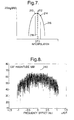
- Figure 6 is a graph of time domain correlation or A( l ⁇ ) as a function of time offset for determining DTO. It shows a maximum 200 at about +0.003 sec.
- Figure 7 illustrates interpolation of maximum values of A( l ⁇ ) (expressed as 20log
- Equation (18) denotes a frequency domain cross correlation.
- the DFO is determined by finding the frequency offset that maximises the magnitude of the correlation expressed as A( l ⁇ ).
- parabolic interpolation of the logarithms of the three largest correlations is employed to determine the peak correlation and the estimate of DFO.
- the interpolation should use a sinx/x interpolation function to achieve the correct result on the linear signal magnitudes. Because simple parabolic interpolation is used on the logarithmic signal magnitudes, a degraded interpolation accuracy is achieved.
- time domain signals are windowed with a Hamming window before transforming to the frequency domain. This windowing function reduces the sidelobes in the correlation response to a negligible level thus enabling an accurate interpolation using the parabolic interpolation on the logarithm of the magnitude of the three largest components.
- Figure 8 is a graph of frequency domain correlation or A( l ⁇ ) as a function of frequency offset ⁇ for the determination of DFO. It shows a maximum 240 at a value of ⁇ of about +80Hz.
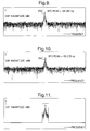
- Figures 9 and 10 are graphs of CAFs against frequency (ie in the frequency domain) for an unknown transmitter 10 and a reference transmitter 22 respectively. These data have been obtained from actual signals and satellites. It can be seen that there is no single peak so that the peak interpolation technique described previously will not be effective. Figures 9 and 10 have similar structures with peaks 250 (-59.281 Hz) and 252 (-59.276 Hz) respectively.
- the procedure to refine the correlations in Figures 9 and 10 is as follows.
- the CAF for the reference signal is excised to remove components away from the correlation peak as shown in Figure 11. The purpose is to reduce noise on the inverse transformed signals.
- the reference CAF is inverse Fourier transformed to the time domain.
- their time domain waveforms are multiplied together. This involves each component of the time domain product typified by Equation (15) for the unknown signal being multiplied by the complex conjugate of the corresponding component of the filtered time domain product for the reference signal. The product of this multiplication is then transformed back to the frequency domain.
- the resulting relative CAF is shown in Figure 12, in which correlation magnitude is plotted against frequency, and the CAF has a maximum 270 at -0.038Hz.
- phase perturbations break down into components as follows:- where;
- the residual phase component which remains after processing in accordance with Equation (21) is a combination of the residual DFO of the unknown signals relative to that of the reference signals together with additional phase corrections.
- phase corrections occur due to the change of DFO with time and the differential effects of the atmosphere on the uplinks to the two satellites 14 and 16 from the unknown and reference transmitters 10 and 22.
- For a second satellite 16 three degrees away in its orbit from a first satellite 14 experiencing interference atmospheric effects substantially cancel so that processing in accordance with Equation (21) yields the residual DFO of the unknown signals relative to that of the reference signals as illustrated in Figure 12.
- processing using reference signals in accordance with the invention compensates for phase noise and residual frequency drift.
- the former is particularly important at low values of satellite orbital inclination below 0.05 degrees, and the latter is particularly important at high values of satellite orbital inclination above 0.5 degrees.
- phase compensation technique is also applied to the determination of DTO for the unknown signal when the signal bandwidth is small ( ⁇ 100 kHz) and the processing gain is large (>60 dB). For large processing gains and narrow bandwidth signals, the duration of the waveform exceeds a few seconds, which is the typical coherence time of the satellite turnround oscillators, and consequently the correlation strength is degraded. Applying the phase compensation technique enables the full correlation strength to be achieved.
- the first stage is to obtain a so-called global location solution.
- the unknown and reference DTOs are DTO(unk) and DTO(ref) respectively, and treating the unknown and reference uplink path indicia l 1 u , l 2 u , l 1 r and l 2 r in Figure 1 as vectors each representing the corresponding transmitter/satellite separation in magnitude and direction, then by geometry:- where l 21 ( r ) is the DSR from the unknown transmitter, l 21 ( r 0 ) is the DSR from the reference transmitter and c is the velocity of light. Furthermore r and r 0 are the position vectors of the unknown transmitter 10 and the reference transmitter 22 from the centre of the Earth as origin in each case.
- the Doppler frequency shift for a signal travelling on a path via a satellite is due to uplink DSRR at the uplink frequency and downlink DSRR at the downlink frequency.
- the uplink and downlink frequencies differ because of the frequency shift introduced by the satellite turnround oscillator.
- f T is the satellite turnround oscillator frequency.
- Equation (27) the last two terms on the right hand side of Equation (27) become the DSRR of that site.
- Equations (24) and (27) relate the measured values of DTO and DFO of an unknown transmitter relative to a reference transmitter to the DSR and DSRR of the unknown transmitter relative to the reference transmitter.
- the DTO and DFO are measurable as previously described and the DSR and DSRR are the geometrical values that can be used to locate the unknown transmitter.
- the relationship between the DSR and positions is found approximately through a Taylor type expansion to relate the DSR at the unknown transmitter location to the DSR at the known transmitter location. A similar expansion is performed for DSRR.
- e x , e y ,& e z are unit vectors along x, y and z orthogonal axes.
- FIG. 13 there is shown a geometrical representation of the determination of the location of the unknown transmitter, the Earth 300 and its centre 304 being illustrated.
- the vector gradient terms on the left hand side of Equations (32) and (31) corresponding to DSR and DSRR are shown as vectors 310 and 312 respectively.
- the reference transmitter site is shown by the vector r 0 at 314 and the unknown source is shown by the vector r at 316.
- a first semi-angle 318 is subtended at the centre 304 of the Earth by a first circle 320 on the surface of the Earth.
- a second semi-angle 322 is subtended at the centre 304 of the Earth by a circle 324 on the surface of the Earth.
- the unknown transmitter is located at the intersection of the circles 320 and 324.
- Equations (31) and (32) In order to solve Equations (31) and (32) for r , the left and right hand sides are treated as being exactly equal and a first approximation r 1 is substituted for r on the left hand side.
- the right hand sides of Equations (31) and (32) are dependent on measured values of DTO and DFO, the positions and velocities of the satellites 14 and 16, the location of the reference transmitter 22 and the receivers 18A and 18B.
- the vector gradient terms on the left hand side of Equations (31) and (32) are dependent on the positions and velocities of the satellites 14 and 16 and the location of the reference transmitter 22. Therefore, all terms are known in Equations (31) and (32) except for the vector r 1 316 substituted for r (which defines the first estimate of the location of the unknown transmitter).
- Equations (31) and (32) are constant for given reference site 314 and satellite positions and velocities, and they constitute a statement that the vector dot product of the unknown source position vector 316 with the (respective) DSR and DSRR gradient vectors 310 and 312 is constant. If the Earth were to have been spherical, the unknown source position vector 316 would be of constant magnitude, and the locus of points of constant magnitude would be the circle 320 subtending a constant semi-angle 318 at the centre of the Earth.
- the unknown signal source is constrained to trace out on the surface of the (spherical) Earth a second circle 324 which subtends a constant semi-angle 322 at the centre of the Earth 304.
- the circles 320 and 324 intersect at two positions 326 and 328.
- one of these positions 326 is visible to both satellites 14 and 16, whereas the other 328 is not and is discounted.
- the former position visible to both satellites is the required location of the unknown source 10.
- Equations (31) and (32) are recast to give:- r 2 .
- ⁇ l 21 (r 1 ) ⁇ k l 21 (r,r 1 ) + r 1 .
- ⁇ ⁇ 21 (r 1 ) ⁇ k ⁇ 21 (r,r 1 ) + r 1 .
- Equation (37) is the difference between the measured uplink DSR and that calculated based on the determined position r 1 .
- ⁇ k ⁇ 21 ( r , r 1 ) in Equation (38) is the difference between the measured uplink DSRR and that calculated based on the determined position r 1 .
- the process of recalculating r j from r j-1 is iterated until the difference
- the number of iterations required to achieve the 50 km convergence is typically three, but is dependent on the favourability of the satellite orbits.
- Equations (24) and (27) relate the DSR and DSRR to the observed DTO and DFO.
- the initial (or global) location solution can be substituted into the right hand sides of Equations (24) and (27) to achieve predictions of the values on the left hand sides of these equations.
- the differences between the observed and predicted DTO and DFO are used to derive error terms to relate to the errors in position.
- the d r term on the left hand sides of Equations (37) and (38) is the residual error in the unknown transmitter location.
- the d r term only has components dE and dN in the azimuth plane along the East and North directions respectively.
- Equation (42) the dE and dN terms are estimated and are used to refine the estimate of the unknown transmitter location r .
- This provides a new position estimate r , and the local location solution can be iterated and the position estimate refined further until a convergent solution is obtained. Because the local location solution uses the exact form of equations, the solution obtained will be exact to the extent set by the measurement, propagation and ephemeris errors.
- Equations (24) and (27) relate DSR to DTO and DSRR to DFO. It is also possible to locate an unknown source using the following combinations of observations:-
- Equation (28) and (29) instead of expressions for l 21 ( r ) and ⁇ 21 ( r ), there would be two expressions for either l 21 ( r ) or ⁇ 21 ( r ) at respective times or for respective pairings.
- Equations (42) can also be used to estimate location errors due to the effect of measurement and other errors.
- the dk terms express the errors and the dr term is the location error.
- measurement and other errors can often be described as random, a statistical approach is used and a root mean square position error derived.
- Tables 1 and 2 show probable error levels in DTO and DFO measurements contributed by various error terms with and without the use of a reference signal in accordance with the invention. Effect of reference signal on DTO error Error term Value without reference signal Value with reference signal Propagation 5x10 -8 s/0.26 km 2x10 -8 s/0.1 km Satellite delay 1x10 -8 s/0.05 km 0 s/0 km Satellite position 2x10 -6 s/10.4 km 1x10 -7 s/0.52 km Time Difference between Receivers 1x10 -7 s/0.52 km 5x10 -9 s/0.026 km Effect of reference signal on DFO error Error term Value without reference Value with reference Satellite turnround oscillators 10 Hz/11,700 km 0 Hz/0 km Satellite velocity 2 Hz/2340 km 1.4x10 -2 Hz/16.4 km Frequency Difference between Receivers 10 Hz/11,700 km 0 Hz/0 km
- Table 1 shows that the dominant error in DTO after normalisation is the satellite position error
- Table 2 shows that the dominant error in DFO after normalisation is the satellite velocity error.
- Tables I and 2 were obtained using typical values of position and velocity errors for satellites that are subject to routine stationkeeping of their geosynchronous orbit to maintain them within a longitude band of + 0.05 deg and a latitude band of ⁇ 0.05 deg.
- the two satellites were located at longitudes 7 deg East and 10 deg East and the 'unknown' signal was located at Paris, France ( approximate longitude 2.5 deg E, latitude 50 deg N) and the reference signal transmitter and monitoring station were co-located at Defford, UK (lon 2.14 deg W, lat 52.1 deg N).
- the invention provides for acquisition and sampling of a signal from a reference transmitter of known location 22 simultaneously with, synchronously and with phase and frequency coherence to a signal of unknown location at separate receivers sites 32A and 32B and the subsequent processing of the signal samples at a single processing site 34. It enables reduction of effects from satellite and ground station local oscillator phase noise, frequency offset and drift with time thereby improving the accuracy of DFO measurement relative to that of the reference transmitter. This cancellation is especially important with narrowband signals (less than 100 kHz) for which long time samples (tens of seconds) are needed to realise detection of a very weak signal overspilt by the unknown transmitter into an adjacent satellite channel and subsequent, satisfactory measurement of DTO and relative DFO.
- relative DFO measurement enables frequency drift effects due to satellite motion of satellites in inclined geosynchronous orbits to be substantially cancelled.
- This effect can be seen from Table 3 where for a given bandwidth of unknown signal and subsequent integration time T a minimum resolution of a frequency slot for DFO processing Af can be defined limited by this integration time. Over this integration time, the DFO of a signal has not to drift by a frequency slot. This, in turn, limits the maximum possible inclination angle of the geosynchronous satellite orbit to the equatorial plane. From these considerations, a maximum inclination for a raw DFO measurement can be defined. Likewise a maximum inclination for a DFO measurement relative to a reference transmitter can be defined.
- Table 3 illustrates that typical prior art systems are unable to work effectively with satellites with orbits having an inclination angle of more than 0.1 deg to the Earth's equator.
- the example of the invention described with reference to Figures 1 to 13 employs a common timing, frequency and phase reference.
- This enables the unknown signal to be acquired at geographically separate sites that are not themselves coordinated to a common timing, frequency and phase reference, and degradation of subsequent DTO and relative DFO measurements is avoided.
- This enables receiving sites to be located within the downlink coverage areas of satellites 14 and 16 which need not cover common territory and therefore need not be monitorable at a single ground station site, unlike the prior art.
- the unknown signal must be receivable by both satellites 14 and 16 as does the reference signal, but this is not a serious limitation because there are many practical circumstances where this is the case.
- the prior art criterion of monitoring both satellites from a single ground station site is a serious limitation because satellite downlinks do not necessarily have common coverage areas.
- the example of the invention described with reference to Figures 1 to 13 also enables reduction of effects due to satellite ephemeris errors.
- the impact on DFO and DTO of satellite ephemeris errors is to a large extent common between unknown and reference transmitters and therefore substantial cancellation is possible.
- Tables 2 and 3 a pair of geosynchronous satellites located at longitude 7 deg E and 10 deg E, have typical stationkeeping errors that introduce errors of 2 Hz into a measurement of DFO and 2 ⁇ s into a measurement of DTO. This would introduce location errors of around 10 km in relation to DTO and 2340 km in relation to DFO.
- Use of a transmitter at a known location enables substantial correction of ephemeris errors.
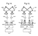
- the reference transmitter 400 incorporates a modulated waveform generator 402 providing a modulation signal to each of two mixers 404X and 404Y. These mixers receive local oscillator signals with nominally equal frequencies of 14.015GHz from respective oscillators 406X and 406Y which are both phase locked to a signal from a reference oscillator 408. Output signals from the mixers 404X and 404Y pass to respective amplifiers 410X and 410Y, and thence to first and second transmit antennas 412X and 412Y respectively.
- the reference transmitter 400 operates as follows.
- Mixers 404X and 404Y produce output signals consisting of modulated signals centred on 14.015 GHz both phase locked to the reference oscillator signal.
- the resulting signals are amplified at 410X and 410Y and then transmitted from respective antennas 412X and 412Y.
- the first antenna 412X has a main transmission lobe directed to the first satellite 14, and the second antenna 412Y has a main transmission lobe directed to the second satellite 16.
- the antenna transmission signals are set to amplitudes substantially lower than that of a typical communications signal, in order to avoid conflict with communications traffic using the satellites 14 and 16.
- the amplitudes are sufficiently high for detection at receivers 18A and 18B, and are higher than the amplitude of a communications transmitter sidelobe. They therefore provide improved signal to noise ratio as compared to the sidelobe equivalent described earlier.
- the frequency of the reference signal can be selected to occupy a frequency free of accesses in either satellite 14 or 16, for example at the edge of the transponder where the channel performance is unacceptable for normal communications signals and therefore would not normally be occupied.
- the level of the reference signal can be reduced to a low level in both satellite 14 and 16 channels so that the impact on satellite channel loading is negligible.
- the reference transmitter 500 incorporates a pseudo-random binary sequence (PRBS) generator 502 providing a modulation signal to each of two mixers 504X and 504Y. These mixers receive local oscillator signals with nominally equal frequencies of 14.015 GHz from respective oscillators 506X and 506Y which are both phase locked to a signal from a reference oscillator 508.
- PRBS pseudo-random binary sequence
- variable attenuators 510X and 510Y to power combiners 512X and 512Y respectively, to which signals from the mixers 504X and 504Y are also fed
- Output signals from the power combiners 512X and 512Y pass to respective amplifiers 514X and 514Y, and thence to first and second transmit antennas 516X and 516Y respectively.
- the reference transmitter 500 operates as follows.
- the mixers 504X and 504Y produce output signals consisting of Pseudo-Random Binary Sequence (PRBS)-modulated 14.015 GHz carrier waves both phase locked to the reference oscillator signal.
- PRBS Pseudo-Random Binary Sequence
- the mixer output signals receive additional carrier wave components at the power combiners 512X and 512Y, the components being adjusted to a convenient amplitude by means of the variable attenuators 510X and 510Y.
- the resulting combined signals are amplified at 514X and 514Y and then transmitted from respective antennas 516X and 516Y.
- the first antenna 516X has a main transmission lobe directed to the first satellite 14, and the second antenna 516Y has a main transmission lobe directed to the second satellite 16.
- the antenna transmission signals are set to amplitudes substantially lower than that of a typical communications signal, in order to avoid conflict with communications traffic using the satellites 14 and 16.
- the amplitudes are sufficiently high for detection at receivers 18A and 18B, and are higher than the amplitude of a communications transmitter sidelobe. They therefore provide improved signal to noise ratio as compared to the sidelobe equivalent described earlier.
- the additional carrier wave component in each of the antenna transmission signals facilitates the determination of the DFO of the reference signal since it can be determined directly from the observation of the CW signal component received in receivers 18A and 18B. Furthermore, it facilitates the process of phase noise cancellation since the phase degradation can be directly observed on the CW signal received in each channel. This phase degradation can be subtracted from the received signal in each channel prior to CAF processing. The effect of the subsequent CAF processing is to derive DFO of the unknown signal relative to the reference signal since the received downlink reference signal contains the DFO shift of the reference signal.
- the PRBS component of the signal provides a well-defined time domain CAF with a single peak at the reference DTO. This is an improvement over the use of an arbitrary reference waveform which may contain hidden periodicity and therefore produce more than one correlation peak in the time domain CAF causing confusion as to the true value of DTO.
- the reference DTO may be determined by geometry from the locations of the reference transmitter 22 and the relay satellites 14 and 16.
- the reference DFO may be determined by geometry from the locations of the reference transmitter 22 and the relay satellites 14 and 16.
- it is necessary to measure the reference DFO to determine the unknown DFO this is because the required accuracy of DFO measurement is in the order of Hz x 10 -3 , and use of the measured reference DFO compensates for an error in this measurement in the order of several Hz introduced by the relay satellites 14 and 16.
Landscapes
- Engineering & Computer Science (AREA)
- Radar, Positioning & Navigation (AREA)
- Remote Sensing (AREA)
- Physics & Mathematics (AREA)
- General Physics & Mathematics (AREA)
- Computer Networks & Wireless Communication (AREA)
- Computer Security & Cryptography (AREA)
- Position Fixing By Use Of Radio Waves (AREA)
- Measurement Of Velocity Or Position Using Acoustic Or Ultrasonic Waves (AREA)
- Eye Examination Apparatus (AREA)
- Electromechanical Clocks (AREA)
- Radar Systems Or Details Thereof (AREA)
- Geophysics And Detection Of Objects (AREA)
- Vehicle Body Suspensions (AREA)
Claims (23)
- Verfahren zum Lokalisieren der Quelle eines unbekannten Signals, das von mehreren Signal-Relaissendern empfangen wird, mit den Schritten:(a) Anordnen mehrerer Empfänger, um das unbekannte Signal von den entsprechenden Signal-Relaissendern zu empfangen;(b) Anordnen der Empfänger, um entsprechende Referenzsignale von entsprechenden Referenzsignal-Relaissendern zu empfangen, wobei die Referenzsignale entweder Nachbildungen eines einzigen Signals sind oder Nachbildungen von Signalen sind, die in der Frequenz, Zeit und Phase mit einem Signal verriegelt sind, und wobei die Referenzsignale von einer Referenzsendeeinrichtung mit bekanntem Ort zu den Signal-Relaissendern gesendet werden;(c) Verarbeiten des entsprechenden unbekannten Signals und des Referenzsignals, die von jedem Empfänger kohärent empfangen werden, so daß diese Signale ihre Zeit- und Phaseninformationen relativ zueinander bewahren;(d) Durchführen einer Kreuzmehrdeutigkeitsfunktion-Verarbeitung der verarbeiteten Referenzsignale, um dem Phasenrauschen und den Frequenzdrifteffekten in den unbekannten Signalen entgegenzuwirken, um wenigstens eine der folgenden Wertegruppen zu ermitteln:(i) Werte des Differential-Zeit-Offset (DTO) und des Differential-Frequenz-Offset (DFO) der unbekannten Signale;(ii) Werte des DTO der unbekannten Signale, die den verschiedenen Signal-Relaissender-Positionen entsprechen;(iii) Werte des DFO der unbekannten Signale, die den verschiedenen Signal-Relaissender-Positionen entsprechen;(iv) Werte des DTO der unbekannten Signale, die verschiedenen Kombinationen von Signal-Relaissendern entsprechen;(v) Werte des DFO der unbekannten Signale, die verschiedenen Kombinationen von Signal-Relaissendern entsprechen;(e) Berechnen der Position der unbekannten Signalquelle anhand der Werte des DTO und/oder des DFO, entsprechend dem in Schritt (d) ermittelten Fall.
- Verfahren nach Anspruch 1, bei dem die Verarbeitung in Schritt (c) mit Bezug auf die Signale durchgeführt wird, die von jedem Empfänger empfangen werden durch Abwärtsumsetzung des unbekannten Signals und des Referenzsignals zu Zwischenfrequenz-(ZF)-Signalen mit vorgegebenen Bandbreiten und Erhalten von digitalen Abtastwerten derselben, wobei die Abtastzeitsteuerung und die Abwärtsumsetzung entsprechend einer präzisen Frequenz- und Zeitsteuerungsnorm gesteuert wird.
- Verfahren nach Anspruch 2, bei dem die unbekannten Signale und die Referenzsignale ZF-Bandbreiten von nicht mehr als 4 MHz aufweisen.
- Verfahren nach Anspruch 3, bei dem der DTO der unbekannten Signale ermittelt wird und das unbekannte Signal eine ZF-Bandbreite aufweist, die zumindest in der Nähe seiner Bandbreite vor der Abwärtsumsetzung liegt.
- Verfahren nach Anspruch 2 oder 3, bei dem der DFO der unbekannten Signale ermittelt wird und die Bandbreite des unbekannten Signals an die Referenzsignal-Bandbreite angepaßt wird.
- Verfahren nach Anspruch 2 oder 3, bei dem der DFO der unbekannten Signale ermittelt wird und die ZF des unbekannten Signals eine Bandbreite von weniger als 100 kHz aufweist.
- Verfahren nach Anspruch 6, bei dem die ZF des unbekannten Signals eine Bandbreite von im wesentlichen gleich 10 kHz aufweist.
- Verfahren nach irgendeinem der vorangehenden Ansprüche, bei dem die Kreuzmehrdeutigkeitsfunktion-Verarbeitung in Schritt (d) des Anspruchs 1 den Schritt des Erzeugens komplexer Daten aus realen Daten mittels eine Hilbert-Transformation-Prozedur enthält.
- Verfahren nach irgendeinem der vorangehenden Ansprüche, bei dem die Kreuzmehrdeutigkeitsfunktion-Verarbeitung in Schritt (d) des Anspruchs 1 durchgeführt wird, um den Referenzsignal-DTO zu ermitteln.
- Verfahren nach Anspruch 9, mit den Schritten:(a) Finden eines vorläufigen Werts des Referenzsignal-DFO durch Auswerten der Kreuzmehrdeutigkeitsfunktion für einen Bereich von Versuchs-Frequenzoffsets, bis ein Funktionsmaximum erhalten wird, das anzeigt, daß der relevante Versuchs-Frequenzoffset der benötigte vorläufige Wert ist;(b) Transformieren der ersten und zweiten Referenzsignale, die den entsprechenden Empfängern zugeordnet sind, in ihre Frequenzbereichsäquivalente;(c) Frequenzverschiebung des ersten Referenzsignals relativ zum zweiten Referenzsignal im Frequenzbereich, wobei die Frequenzverschiebung den vorläufigen Wert des DFO umfaßt;(d) Entfernen irgendwelcher unerwünschten Frequenzkomponenten in den Frequenzbereich-Referenzsignalen;(e) Multiplizieren der konjugierten Komplexen jeder Frequenzkomponente des ersten Referenzsignals mit der entsprechenden Frequenzkomponente des zweiten Referenzsignals im Frequenzbereich, um Frequenzkomponentenprodukte zu erhalten;(f) Transformieren der Frequenzkomponentenprodukte in den Zeitbereich und Erzeugen eines entsprechenden Wertes der Kreuzmehrdeutigkeitsfunktion für jeden Wert des Wertebereichs des relativen Zeitoffsets zwischen den ersten und zweiten Referenzsignalen;(g) Auswählen eines Satzes größter Amplitudenwerte der Kreuzmehrdeutigkeitsfunktion, Erhalten eines Maximumwertes der Amplitude der Kreuzmehrdeutigkeitsfunktion mittels Interpolation zwischen diesen und Herleiten des Referenzsignal-DTO als den relativen Zeitoffset zwischen den ersten und zweiten Referenzsignalen, der diesem Maximumwert entspricht.
- Verfahren nach irgendeinem der vorangehenden Ansprüche, bei dem die Verarbeitung im Schritt (d) des Anspruchs 1 ausgeführt wird, um den Referenzsignal-DFO zu erhalten, und das die Schritte enthält:(a) Ermitteln des DTO zwischen den ersten und zweiten Referenzsignalen, die den entsprechenden Empfängern zugeordnet sind;(b) Einführen einer relativen Zeitverschiebung zwischen den ersten und zweiten Referenzsignalen gleich dem Referenzsignal-DTO;(c) Abtasten der Referenzsignale nach der relativen Zeitverschiebung;(d) Multiplizieren der konjugiert Komplexen jedes ersten Referenzsignals mit einem entsprechenden Abtastwert des zweiten Referenzsignals, um Zeitkomponentenprodukte zu erzeugen;(e) Fourier-Transformation der Zeitkomponentenprodukte in den Frequenzbereich und Erzeugen eines entsprechenden Wertes der Kreuzmehrdeutigkeitsfunktion für jeden Wert eines Wertebereichs des relativen Frequenzoffsets zwischen den ersten und zweiten Referenzsignalen;(f) Auswählen eines Satzes größter Amplitudenwerte der Kreuzmehrdeutigkeitsfunktion, Erhalten eines Maximumwertes der Kreuzmehrdeutigkeitsfunktion mittels Interpolation zwischen diesen und Herleiten des Referenzsignal-DFO als den relativen Frequenzoffset zwischen den ersten und zweiten Referenzsignalen, der diesem Maximumwert entspricht.
- Verfahren nach irgendeinem der vorangehenden Ansprüche, bei dem die Verarbeitung im Schritt (d) des Anspruchs 1 ausgeführt wird, um den DTO des unbekannten Signals zu erhalten, und das die Schritte enthält:(a) Einführen relativer Zeit- und Frequenzverschiebungen zwischen den ersten und zweiten unbekannten Signalen, die den entsprechenden Empfängern zugeordnet sind, wobei die Zeit- und Frequenzverschiebungen gleich dem DTO bzw. dem DFO des Referenzsignals sind;(b) Abtasten der unbekannten Signale nach den relativen Zeit- und Frequenzverschiebungen;(c) Transformieren der ersten und zweiten unbekannten Signale in ihre Frequenzbereich-Äquivalente;(d) Anwenden eines Versuchs-Frequenzoffsets auf das transformierte zweite unbekannte Signal;(e) Entfernen irgendwelcher unerwünschten Frequenzkomponenten in den transformierten unbekannten Signalen;(f) Multiplizieren der konjugierten Komplexen jeder Frequenzkomponente des ersten unbekannten Signals mit der entsprechenden Frequenzkomponente des zweiten unbekannten Signals, um Frequenzkomponentenprodukte zu erhalten;(g) Transformieren der Frequenzkomponentenprodukte in den Zeitbereich, um einen entsprechenden Wert der Kreuzmehrdeutigkeitsfunktion für jeden Wert des Wertebereichs des relativen Zeitoffsets zwischen den ersten und zweiten unbekannten Signalen zu erzeugen;(i) Wiederholen der Schritte (d) bis (g) für einen Bereich von Versuchs-Frequenzoffsets, um Werte der Kreuzmehrdeutigkeitsfunktion zu erhalten;(h) Auswählen eines Satzes größter Amplitudenwerte der Kreuzmehrdeutigkeitsfunktion, Erhalten eines Maximumwertes der Amplitude der Kreuzmehrdeutigkeitsfunktion mittels Interpolation zwischen diesen und Herleiten des DTO des unbekannten Signals als den relativen Zeitoffset zwischen den ersten und zweiten unbekannten Signalen, der diesem Maximumwert entspricht.
- Verfahren nach irgendeinem der vorangehenden Ansprüche, bei dem die Verarbeitung im Schritt (d) des Anspruchs 1 ausgeführt wird, um den DFO des unbekannten Signals zu erhalten, und das eine Stufe enthält, die die Verarbeitung der Referenzsignale umfaßt und die Schritte enthält:(a) Einführen relativer Zeit- und Frequenzverschiebungen zwischen den ersten und zweiten Referenzsignalen, die den entsprechenden Empfängern zugeordnet sind, wobei die Verschiebungen gleich dem DTO bzw. dem DFO des Referenzsignals sind;(b) Abtasten der Referenzsignale nach den relativen Zeit- und Frequenzverschiebungen;(c) Multiplizieren der konjugierten Komplexen jedes ersten Referenzsignalabtastwertes mit dem entsprechenden Abtastwert des zweiten Referenzsignals, um Zeitkomponentenprodukte zu erhalten;(d) Fourier-Transformation der Komponentenprodukte in den Frequenzbereich, um einen entsprechenden Wert der Kreuzmehrdeutigkeitsfunktion für jeden Wert des Wertebereichs des relativen Frequenzoffsets zwischen den ersten und zweiten Referenzsignalen zu erzeugen;(e) Entfernen unerwünschter Frequenzbereichskomponenten aus der Kreuzmehrdeutigkeitsfunktion;(f) Fourier-Transformation der bereinigten Kreuzmehrdeutigkeitsfunktion zurück in den Zeitbereich, um einen Satz gefilterter Zeitbereichsprodukte zwischen den ersten und zweiten Referenzsignalen zu erzeugen, die Phasenrauschen-Perturbationsinformationen enthalten.
- Verfahren nach irgendeinem der vorangehenden Ansprüche, bei dem die Verarbeitung im Schritt (d) des Anspruchs 1 ausgeführt wird, um den DFO des unbekannten Signals zu erhalten, und das eine weitere Stufe enthält, die die Verarbeitung der unbekannten Signale umfaßt und die Schritte enthält:(a) Einführen relativer Zeit- und Frequenzverschiebungen zwischen den ersten und zweiten unbekannten Signalen gleich dem DTO bzw. dem DFO des Referenzsignals;(b) Abtasten der unbekannten Signale nach den relativen Zeit- und Frequenzverschiebungen;(c) Multiplizieren der konjugierten Komplexen jedes ersten unbekannten Signalabtastwertes mit dem entsprechenden Abtastwert des zweiten unbekannten Signals, um Zeitkomponentenprodukte zu erhalten;(d) Multiplizieren jedes Zeitkomponentenprodukts mit der konjugiert Komplexen des gefilterten Zeitkomponentenprodukts der ersten und zweiten Referenzsignale;(e) Fourier-Transformation der Zeitkomponentenprodukte in den Frequenzbereich und Erzeugen eines entsprechenden Wertes der Kreuzmehrdeutigkeitsfunktion für jeden Wert des Wertebereichs des relativen Frequenzoffsets zwischen den ersten und zweiten unbekannten Signalen;(f) Auswählen eines Satzes größter Amplitudenwerte der Kreuzmehrdeutigkeitsfunktion, Erhalten eines Maximumwertes der Kreuzmehrdeutigkeitsfunktion mittels Interpolation zwischen diesen und Herleiten des DFO des unbekannten Signals relativ zum DFO des Referenzsignals als den relativen Frequenzoffset zwischen den ersten und zweiten unbekannten Signalen, der diesem Maximumwert entspricht.
- Verfahren nach irgendeinem der vorangehenden Ansprüche, bei dem die Berechnung der Position des unbekannten Senders in Schritt (e) des Anspruchs 1 beruht auf:(a) Erhalten eines Ausdrucks aus dem DTO des unbekannten Signals und dem DTO des Referenzsignals, unter Verwendung der Differentialneigungsbereiche (DSR) des Referenzsenders und des unbekannten Senders, wobei die DSR in jedem Fall die Längendifferenz der Wege vom entsprechenden Sender zu den Signal-Relaissendern sind;(b) Erhalten eines Ausdrucks aus dem DFO des unbekannten Signals und dem DFO des Referenzsignals, unter Verwendung der Differentialneigungsbereichsraten (DSRR) des Referenzsenders und des unbekannten Senders, wobei die DSRR in jedem Fall die Änderungsrate der entsprechenden DSR sind; und(c) Durchführen einer Taylorreihenanalyse der DSR- und DSRR-Ausdrücke, um den Ort des unbekannten Senders aus den unbekannten und den Referenz-DTOs und -DFOs, die Positionen und Geschwindigkeiten der Relaissender und die Orte der Referenzsender und der Empfänger herzuleiten.
- Verfahren nach Anspruch 15, bei dem der in Schritt (c) dieses Anspruchs hergeleitete Ort ein erster Wert desselben ist, und wobei einer oder mehrere verbesserte Werte desselben durch eine Rückwärtssubstitution des ersten Wertes in der Taylorreihenanalyse und Iteration der Herleitung des Ortes des unbekannten Senders hergeleitet werden.
- Verfahren nach Anspruch 15 oder 16, mit einer Verfeinerung der Herleitung des Ortes des unbekannten Senders mit den Schritten:(a) Erzeugen berechneter Werte des DTO und des DFO des unbekannten Signals aus einem hergeleiteten Wert des Ortes des unbekannten Senders, den Positionen und Geschwindigkeiten der Relaissender und den Orten der Empfänger;(b) Erzeugen einer Korrektur für den hergeleiteten Ort des unbekannten Senders aus den Differenzen zwischen den berechneten Werten des DTO und des DFO des unbekannten Signals und derjenigen, die mittels der Kreuzmehrdeutigkeitsverarbeitung gemessen worden sind.
- Verfahren nach irgendeinem der vorangehenden Ansprüche, bei dem die verarbeiteten Referenzsignale und die verarbeiteten unbekannten Signale vor der Kreuzmehrdeutigkeitsfunktion-Verarbeitung gespeichert werden.
- Vorrichtung zum Lokalisieren der Quelle eines unbekannten Signals, das von mehreren Signal-Relaissendern empfangen wird, wobei die Vorrichtung enthält:(a) mehrere Empfänger zum Empfangen des unbekannten Signals und entsprechender Referenzsignale von den entsprechenden Signal-Relaissendern, wobei die Referenzsignale entweder Nachbildungen eines einzigen Signals sind oder Nachbildungen von Signalen sind, die in der Frequenz, Zeit und Phase mit einem Signal verriegelt sind, und wobei die Referenzsignale von einer Referenzsendeeinrichtung mit bekanntem Ort zu den Signal-Relaissendern gesendet werden;(b) eine Einrichtung zum Verarbeiten des entsprechenden unbekannten Signals und des Referenzsignals, die von jedem Empfänger kohärent empfangen werden, so daß diese Signale ihre Zeit- und Phaseninformationen relativ zueinander bewahren, unabhängig von Signalen, die anderswo empfangen werden;(c) eine Einrichtung zum:(i) Durchführen der Kreuzmehrdeutigkeitsfunktion-Verarbeitung der verarbeiteten Referenzsignale und der verarbeiteten unbekannten Signale und Verwenden der Referenzsignale, um dem Phasenrauschen und den Frequenzdrifteffekten in den unbekannten Signalen entgegenzuwirken, um wenigstens eine der folgenden Wertegruppen zu ermitteln:(1) Werte des Differential-Zeit-Offset (DTO) und des Differential-Frequenz-Offset (DFO) der unbekannten Signale;(2) Werte des DTO der unbekannten Signale, die den verschiedenen Signal-Relaissender-Positionen entsprechen;(3) Werte des DFO der unbekannten Signale, die den verschiedenen Signal-Relaissender-Positionen entsprechen;(4) Werte des DTO der unbekannten Signale, die verschiedenen Kombinationen von Signal-Relaissendern entsprechen;(5) Werte des DFO der unbekannten Signale, die verschiedenen Kombinationen von Signal-Relaissendern entsprechen; und(ii) Berechnen der Position der unbekannten Signalquelle anhand der Werte des DTO und/oder des DFO, entsprechend dem in der Kreuzmehrdeutigkeitsfunktion-Verarbeitung ermittelten Fall.
- Vorrichtung nach Anspruch 19, die so beschaffen ist, daß die empfangenen Signale geeignet in der Zeit und/oder in der Frequenz verschoben werden, entsprechend dem Fall der für den DTO und/oder den DFO erhaltenen Werte, und daß weitere Werte derselben aus solchen Offsetsignalen erhalten werden.
- Vorrichtung nach Anspruch 19 oder 20, mit einer Referenzsignalsendeeinrichtung zum Senden von Referenzsignalen mit im wesentlichen gleicher Stärke zu den Signal-Relaissendern.
- Vorrichtung nach Anspruch 19 oder 20, mit einer Referenzsignalsendeeinrichtung zum Senden von Referenzsignalen, die modulierte und unmodulierte Trägerwellenkomponenten enthalten, zu den Signal-Relaissendern.
- Vorrichtung nach Anspruch 19 oder 20, mit einer Einrichtung zum Speichern der verarbeiteten Referenzsignale und der verarbeiteten unbekannten Signale vor der Kreuzmehrdeutigkeitsfunktion-Verarbeitung.
Applications Claiming Priority (1)
| Application Number | Priority Date | Filing Date | Title |
|---|---|---|---|
| PCT/GB1995/002211 WO1997011383A1 (en) | 1995-09-20 | 1995-09-20 | Locating the source of an unknown signal |
Publications (2)
| Publication Number | Publication Date |
|---|---|
| EP0852017A1 EP0852017A1 (de) | 1998-07-08 |
| EP0852017B1 true EP0852017B1 (de) | 1999-07-28 |
Family
ID=10769104
Family Applications (1)
| Application Number | Title | Priority Date | Filing Date |
|---|---|---|---|
| EP95933479A Expired - Lifetime EP0852017B1 (de) | 1995-09-20 | 1995-09-20 | Positionsbestimmung der quelle eines unbekannten signales |
Country Status (15)
| Country | Link |
|---|---|
| US (1) | US6018312A (de) |
| EP (1) | EP0852017B1 (de) |
| JP (1) | JP3556952B2 (de) |
| KR (1) | KR100319993B1 (de) |
| AT (1) | ATE182687T1 (de) |
| AU (1) | AU708274B2 (de) |
| BR (1) | BR9510640A (de) |
| CA (1) | CA2232396C (de) |
| DE (1) | DE69511118T2 (de) |
| ES (1) | ES2133806T3 (de) |
| GB (1) | GB2321356B (de) |
| GR (1) | GR3031185T3 (de) |
| HK (1) | HK1015880A1 (de) |
| MX (1) | MX9802116A (de) |
| WO (1) | WO1997011383A1 (de) |
Families Citing this family (129)
| Publication number | Priority date | Publication date | Assignee | Title |
|---|---|---|---|---|
| US6215442B1 (en) * | 1997-02-03 | 2001-04-10 | Snaptrack, Inc. | Method and apparatus for determining time in a satellite positioning system |
| US7198230B2 (en) * | 1997-10-14 | 2007-04-03 | The Directv Group, Inc. | Method and system for maximizing satellite constellation coverage |
| US5936570A (en) * | 1998-03-05 | 1999-08-10 | Teledesic Llc | Low-earth orbit satellite acquisition and synchronization system using a beacon signal |
| US6317077B1 (en) * | 1999-02-22 | 2001-11-13 | Hughes Electronics Corporation | Method and system of determining user terminal position using multiple satellites |
| US6147640A (en) * | 1999-03-16 | 2000-11-14 | Hughes Electronics Corporation | Communications satellite interference location system |
| US6493380B1 (en) * | 1999-05-28 | 2002-12-10 | Nortel Networks Limited | System and method for estimating signal time of arrival |
| GB9919525D0 (en) * | 1999-08-19 | 1999-10-20 | Secr Defence | Method and apparatus for locating the source of an unknown signal |
| FI106655B (fi) * | 1999-09-27 | 2001-03-15 | Nokia Corp | Menetelmä ja järjestelmä lähettimen paikantamiseksi |
| FR2801682B1 (fr) * | 1999-11-29 | 2006-09-08 | Cit Alcatel | Procede de localisation d'emetteur parasite pour systeme de telecommunications par satellite |
| AU2000279094A1 (en) * | 2000-09-28 | 2002-04-08 | Ses Astra S.A. | Satellite communications system |
| FR2819657B1 (fr) * | 2001-01-15 | 2003-04-11 | Cit Alcatel | Procede et dispositif de localisation d'un emetteur terrestre a partir d'un satellite |
| GB2373940A (en) * | 2001-03-27 | 2002-10-02 | Secr Defence | Locating the source of an unknown signal |
| US6759983B2 (en) | 2001-03-28 | 2004-07-06 | Strategic Analysis, Inc. | Method and device for precise geolocation of low-power, broadband, amplitude-modulated signals |
| FR2823857B1 (fr) | 2001-04-23 | 2006-11-24 | Agence Spatiale Europeenne | Procede de determination de la position d'une balise emettrice |
| AU2002305411A1 (en) * | 2001-05-08 | 2002-11-18 | Comsat Corporation | Method and apparatus for measuring adjacent satellite interference |
| US6784827B2 (en) * | 2001-12-21 | 2004-08-31 | International Business Machines Corporation | Determining a time of arrival of a sent signal |
| WO2003069941A1 (en) * | 2002-02-15 | 2003-08-21 | Nokia Corporation | Positioning in a telecommunications system |
| US6891500B2 (en) * | 2002-03-18 | 2005-05-10 | Christopher J. Hall | Method and apparatus for geolocating a wireless communications device |
| US20050003828A1 (en) * | 2002-04-09 | 2005-01-06 | Sugar Gary L. | System and method for locating wireless devices in an unsynchronized wireless environment |
| WO2004052027A2 (en) * | 2002-11-27 | 2004-06-17 | Cognio, Inc | System and method for locating sources of unknown wireless radio signals |
| US6882936B2 (en) * | 2003-03-03 | 2005-04-19 | Lockheed Martin Corporation | Integrated GPS/interference location system with anti-jam processor |
| US7702002B2 (en) * | 2004-01-28 | 2010-04-20 | Qualcomm Incorporated | Rapid acquisition methods and apparatus for GPS signals |
| US7783110B2 (en) * | 2004-12-01 | 2010-08-24 | Bae Systems Information And Electronic Systems Integration Inc. | Semicoherent channel estimator |
| JP4592506B2 (ja) * | 2005-06-15 | 2010-12-01 | 株式会社東芝 | アップリンク干渉源位置特定装置及びその方法 |
| US7508344B2 (en) * | 2005-11-29 | 2009-03-24 | L-3 Communications Integrated Systems, Lp | Systems and methods for TDOA/FDOA location |
| US7498986B2 (en) * | 2005-12-05 | 2009-03-03 | Honeywell International Inc. | Methods and systems for locating actuators for improvised explosive devices |
| US7456788B2 (en) * | 2005-12-22 | 2008-11-25 | L-3 Communications Integrated Systems L.P. | Method and apparatus for reducing geolocation ambiguity in signal tracking |
| US7477191B2 (en) * | 2006-03-03 | 2009-01-13 | Cisco Technology, Inc. | System and method for performing time difference of arrival location without requiring a common time base or clock calibration |
| GB0606501D0 (en) * | 2006-03-31 | 2006-05-10 | Qinetiq Ltd | Satellite ephemeris error |
| JP2008064566A (ja) * | 2006-09-06 | 2008-03-21 | Mitsubishi Electric Corp | 軌道推定方法とその装置 |
| GB2443226B (en) * | 2006-10-28 | 2011-08-17 | Qinetiq Ltd | Method and apparatus for locating the source of an unknown signal |
| US7471245B2 (en) * | 2007-01-31 | 2008-12-30 | L3 Communications Integrated Systems, L.P. | Method and apparatus for estimating geolocations |
| US7663547B2 (en) * | 2007-04-13 | 2010-02-16 | Glowlink Communications Technology, Inc. | Determining a geolocation solution of an emitter on earth based on weighted least-squares estimation |
| US7667640B2 (en) * | 2007-04-13 | 2010-02-23 | Glowlink Communications Technology, Inc. | Determining a geolocation solution of an emitter on earth using satellite signals |
| GB0719004D0 (en) * | 2007-09-27 | 2008-01-02 | Qinetiq Ltd | Interference power measurement |
| US7626546B2 (en) * | 2007-09-27 | 2009-12-01 | L-3 Communications Integrated Systems L.P. | Methods and systems for detection and location of multiple emitters |
| US8892112B2 (en) | 2011-07-21 | 2014-11-18 | At&T Mobility Ii Llc | Selection of a radio access bearer resource based on radio access bearer resource historical information |
| JP5183246B2 (ja) * | 2008-02-25 | 2013-04-17 | 三菱電機株式会社 | 未知送信局の測位装置及び測位方法 |
| US8116419B2 (en) * | 2008-07-14 | 2012-02-14 | Alcatel Lucent | Methods and apparatuses for estimating time delay and frequency offset in single frequency networks |
| ATE524747T1 (de) | 2008-07-24 | 2011-09-15 | Ses Astra Sa | System und verfahren zur berechnung einer raumflugkörperposition |
| US20180329018A9 (en) * | 2008-07-25 | 2018-11-15 | etherwhere Coporation | System framework for mobile device location |
| JP2010060303A (ja) * | 2008-09-01 | 2010-03-18 | Mitsubishi Electric Corp | 測位装置 |
| US7893875B1 (en) * | 2008-10-31 | 2011-02-22 | The United States Of America As Represented By The Director National Security Agency | Device for and method of geolocation |
| US8326319B2 (en) | 2009-01-23 | 2012-12-04 | At&T Mobility Ii Llc | Compensation of propagation delays of wireless signals |
| US7911385B2 (en) * | 2009-02-27 | 2011-03-22 | Harris Corporation | RF transmitter geolocation system and related methods |
| US8134493B2 (en) * | 2009-07-02 | 2012-03-13 | Raytheon Company | System and method for precision geolocation utilizing multiple sensing modalities |
| US8179317B2 (en) * | 2009-09-10 | 2012-05-15 | Bae Systems Information And Electronic Systems Integration Inc. | Method and apparatus for passive geolocation using synthetic-aperture processing |
| US9053513B2 (en) | 2010-02-25 | 2015-06-09 | At&T Mobility Ii Llc | Fraud analysis for a location aware transaction |
| US8254959B2 (en) | 2010-02-25 | 2012-08-28 | At&T Mobility Ii Llc | Timed fingerprint locating for idle-state user equipment in wireless networks |
| US9196157B2 (en) | 2010-02-25 | 2015-11-24 | AT&T Mobolity II LLC | Transportation analytics employing timed fingerprint location information |
| US9008684B2 (en) | 2010-02-25 | 2015-04-14 | At&T Mobility Ii Llc | Sharing timed fingerprint location information |
| US8224349B2 (en) | 2010-02-25 | 2012-07-17 | At&T Mobility Ii Llc | Timed fingerprint locating in wireless networks |
| US8447328B2 (en) | 2010-08-27 | 2013-05-21 | At&T Mobility Ii Llc | Location estimation of a mobile device in a UMTS network |
| US9009629B2 (en) | 2010-12-01 | 2015-04-14 | At&T Mobility Ii Llc | Motion-based user interface feature subsets |
| US8878726B2 (en) * | 2011-03-16 | 2014-11-04 | Exelis Inc. | System and method for three-dimensional geolocation of emitters based on energy measurements |
| US8248297B1 (en) * | 2011-04-11 | 2012-08-21 | Advanced Testing Technologies, Inc. | Phase noise measurement system and method |
| US8878725B2 (en) | 2011-05-19 | 2014-11-04 | Exelis Inc. | System and method for geolocation of multiple unknown radio frequency signal sources |
| US8615190B2 (en) | 2011-05-31 | 2013-12-24 | Exelis Inc. | System and method for allocating jamming energy based on three-dimensional geolocation of emitters |
| US8612410B2 (en) | 2011-06-30 | 2013-12-17 | At&T Mobility Ii Llc | Dynamic content selection through timed fingerprint location data |
| US9462497B2 (en) | 2011-07-01 | 2016-10-04 | At&T Mobility Ii Llc | Subscriber data analysis and graphical rendering |
| US9519043B2 (en) | 2011-07-21 | 2016-12-13 | At&T Mobility Ii Llc | Estimating network based locating error in wireless networks |
| US8897802B2 (en) | 2011-07-21 | 2014-11-25 | At&T Mobility Ii Llc | Selection of a radio access technology resource based on radio access technology resource historical information |
| US8761799B2 (en) | 2011-07-21 | 2014-06-24 | At&T Mobility Ii Llc | Location analytics employing timed fingerprint location information |
| US8723730B2 (en) | 2011-07-27 | 2014-05-13 | Exelis Inc. | System and method for direction finding and geolocation of emitters based on line-of-bearing intersections |
| JP5599371B2 (ja) * | 2011-07-28 | 2014-10-01 | 三菱電機株式会社 | 測位装置 |
| WO2013066463A2 (en) * | 2011-08-12 | 2013-05-10 | Bae Systems Information & Electronic System Integration Inc. | Link 16-based geolocation of hostile jammers |
| US8666390B2 (en) | 2011-08-29 | 2014-03-04 | At&T Mobility Ii Llc | Ticketing mobile call failures based on geolocated event data |
| US8923134B2 (en) | 2011-08-29 | 2014-12-30 | At&T Mobility Ii Llc | Prioritizing network failure tickets using mobile location data |
| US8762048B2 (en) | 2011-10-28 | 2014-06-24 | At&T Mobility Ii Llc | Automatic travel time and routing determinations in a wireless network |
| US8909247B2 (en) | 2011-11-08 | 2014-12-09 | At&T Mobility Ii Llc | Location based sharing of a network access credential |
| US9026133B2 (en) | 2011-11-28 | 2015-05-05 | At&T Mobility Ii Llc | Handset agent calibration for timing based locating systems |
| US8970432B2 (en) | 2011-11-28 | 2015-03-03 | At&T Mobility Ii Llc | Femtocell calibration for timing based locating systems |
| US8644794B1 (en) | 2012-02-02 | 2014-02-04 | Google Inc. | Luggage locator |
| US8866672B2 (en) | 2012-04-05 | 2014-10-21 | L-3 Communications Integrated Systems Lp | Cooperative systems and methods for TDOA-based emitter location |
| US8925104B2 (en) | 2012-04-13 | 2014-12-30 | At&T Mobility Ii Llc | Event driven permissive sharing of information |
| US8929827B2 (en) | 2012-06-04 | 2015-01-06 | At&T Mobility Ii Llc | Adaptive calibration of measurements for a wireless radio network |
| US9094929B2 (en) | 2012-06-12 | 2015-07-28 | At&T Mobility Ii Llc | Event tagging for mobile networks |
| US9326263B2 (en) | 2012-06-13 | 2016-04-26 | At&T Mobility Ii Llc | Site location determination using crowd sourced propagation delay and location data |
| US9046592B2 (en) | 2012-06-13 | 2015-06-02 | At&T Mobility Ii Llc | Timed fingerprint locating at user equipment |
| US8938258B2 (en) * | 2012-06-14 | 2015-01-20 | At&T Mobility Ii Llc | Reference based location information for a wireless network |
| US8897805B2 (en) | 2012-06-15 | 2014-11-25 | At&T Intellectual Property I, L.P. | Geographic redundancy determination for time based location information in a wireless radio network |
| US9408174B2 (en) | 2012-06-19 | 2016-08-02 | At&T Mobility Ii Llc | Facilitation of timed fingerprint mobile device locating |
| US8892054B2 (en) | 2012-07-17 | 2014-11-18 | At&T Mobility Ii Llc | Facilitation of delay error correction in timing-based location systems |
| US9351223B2 (en) | 2012-07-25 | 2016-05-24 | At&T Mobility Ii Llc | Assignment of hierarchical cell structures employing geolocation techniques |
| KR101224512B1 (ko) * | 2012-09-03 | 2013-01-21 | 한국항공우주연구원 | Tdoa 기법을 기반으로 하는 미지신호 발생원 위치 측정방법 |
| EP2735883A1 (de) | 2012-11-27 | 2014-05-28 | Eutelsat S.A. | Verfahren zur Geolokalisierung eines Endgeräts, das ein einzelnes Signal zu einem Satelliten sendet |
| US10720986B2 (en) | 2012-12-05 | 2020-07-21 | Ses S.A. | Apparatuses, systems and methods for obtaining information about electromagnetic energy emitted from the earth, such as for locating an interference source on earth |
| US9086471B2 (en) | 2012-12-05 | 2015-07-21 | Ses S.A. | Apparatuses, systems and methods for obtaining information about electromagnetic energy emitted from the earth, such as for locating an interference source on earth |
| US10231206B2 (en) | 2013-03-15 | 2019-03-12 | DGS Global Systems, Inc. | Systems, methods, and devices for electronic spectrum management for identifying signal-emitting devices |
| US10219163B2 (en) | 2013-03-15 | 2019-02-26 | DGS Global Systems, Inc. | Systems, methods, and devices for electronic spectrum management |
| US9288683B2 (en) * | 2013-03-15 | 2016-03-15 | DGS Global Systems, Inc. | Systems, methods, and devices for electronic spectrum management |
| US10257729B2 (en) | 2013-03-15 | 2019-04-09 | DGS Global Systems, Inc. | Systems, methods, and devices having databases for electronic spectrum management |
| US11646918B2 (en) | 2013-03-15 | 2023-05-09 | Digital Global Systems, Inc. | Systems, methods, and devices for electronic spectrum management for identifying open space |
| US10257727B2 (en) | 2013-03-15 | 2019-04-09 | DGS Global Systems, Inc. | Systems methods, and devices having databases and automated reports for electronic spectrum management |
| US10257728B2 (en) | 2013-03-15 | 2019-04-09 | DGS Global Systems, Inc. | Systems, methods, and devices for electronic spectrum management |
| US10244504B2 (en) | 2013-03-15 | 2019-03-26 | DGS Global Systems, Inc. | Systems, methods, and devices for geolocation with deployable large scale arrays |
| US10237770B2 (en) | 2013-03-15 | 2019-03-19 | DGS Global Systems, Inc. | Systems, methods, and devices having databases and automated reports for electronic spectrum management |
| US10271233B2 (en) | 2013-03-15 | 2019-04-23 | DGS Global Systems, Inc. | Systems, methods, and devices for automatic signal detection with temporal feature extraction within a spectrum |
| US8750156B1 (en) | 2013-03-15 | 2014-06-10 | DGS Global Systems, Inc. | Systems, methods, and devices for electronic spectrum management for identifying open space |
| US10122479B2 (en) | 2017-01-23 | 2018-11-06 | DGS Global Systems, Inc. | Systems, methods, and devices for automatic signal detection with temporal feature extraction within a spectrum |
| US10299149B2 (en) | 2013-03-15 | 2019-05-21 | DGS Global Systems, Inc. | Systems, methods, and devices for electronic spectrum management |
| US10444371B2 (en) * | 2014-03-21 | 2019-10-15 | The Boeing Company | Interference geolocation using a satellite constellation |
| US9766343B2 (en) * | 2014-06-19 | 2017-09-19 | Novatel Inc. | System and method for determining location of an interfering signal source |
| US9351111B1 (en) | 2015-03-06 | 2016-05-24 | At&T Mobility Ii Llc | Access to mobile location related information |
| CN104900752A (zh) * | 2015-04-14 | 2015-09-09 | 中国电子科技集团公司第四十四研究所 | 黑硅层制作方法及黑硅pin光电探测器制备方法 |
| EP3357285B1 (de) * | 2015-10-02 | 2021-07-21 | Telefonaktiebolaget LM Ericsson (PUBL) | Synchronisieren von uhren in einem kommunikationsnetzwerk |
| EP3156814B1 (de) | 2015-10-14 | 2024-03-27 | Bull Sas | Verfahren zum auffinden einer terrestrischen übertragungsquelle eines unbekannten signals |
| JP6009131B1 (ja) * | 2015-12-25 | 2016-10-19 | 三菱電機株式会社 | 速度推定装置 |
| US11187778B2 (en) * | 2016-01-13 | 2021-11-30 | Hoopo Systems Ltd. | Method and system for radiolocation |
| KR102625211B1 (ko) * | 2016-05-16 | 2024-01-16 | 한국전자통신연구원 | 무선 통신 신호의 수신 시각 산출 장치 및 방법 |
| US10521657B2 (en) | 2016-06-17 | 2019-12-31 | Li-Cor, Inc. | Adaptive asymmetrical signal detection and synthesis methods and systems |
| US10151781B2 (en) | 2016-06-17 | 2018-12-11 | Li-Cor, Inc. | Spectral response synthesis on trace data |
| US9971936B2 (en) * | 2016-06-17 | 2018-05-15 | Li-Cor, Inc. | Adaptive signal detection and synthesis on trace data |
| US10498951B2 (en) | 2017-01-23 | 2019-12-03 | Digital Global Systems, Inc. | Systems, methods, and devices for unmanned vehicle detection |
| US10700794B2 (en) | 2017-01-23 | 2020-06-30 | Digital Global Systems, Inc. | Systems, methods, and devices for automatic signal detection based on power distribution by frequency over time within an electromagnetic spectrum |
| US10529241B2 (en) | 2017-01-23 | 2020-01-07 | Digital Global Systems, Inc. | Unmanned vehicle recognition and threat management |
| US10459020B2 (en) | 2017-01-23 | 2019-10-29 | DGS Global Systems, Inc. | Systems, methods, and devices for automatic signal detection based on power distribution by frequency over time within a spectrum |
| IL256679B2 (en) * | 2017-12-31 | 2023-02-01 | Elta Systems Ltd | Systems and methods for locating a signal source |
| US10516972B1 (en) | 2018-06-01 | 2019-12-24 | At&T Intellectual Property I, L.P. | Employing an alternate identifier for subscription access to mobile location information |
| US10943461B2 (en) | 2018-08-24 | 2021-03-09 | Digital Global Systems, Inc. | Systems, methods, and devices for automatic signal detection based on power distribution by frequency over time |
| US11022670B1 (en) * | 2018-09-13 | 2021-06-01 | L3Harris Technologies, Inc. | Opportunistic adjustable rate cross-ambiguity function geolocation |
| WO2020089899A1 (en) * | 2018-11-01 | 2020-05-07 | Hoopo Systems Ltd. | Method and system for radiolocation at reduced data transfer |
| CN110324041B (zh) * | 2019-07-11 | 2022-11-18 | 中国人民解放军国防科技大学 | 一种宽带交叉采样系统通道失配估计方法 |
| KR102150099B1 (ko) * | 2019-10-01 | 2020-08-31 | 국방과학연구소 | Fm 신호 기반의 pcl 시스템에서 표적 데이터를 추출하는 방법 및 장치 |
| RU2717231C1 (ru) * | 2019-10-08 | 2020-03-19 | федеральное государственное казенное военное образовательное учреждение высшего образования "Военная академия связи имени Маршала Советского Союза С.М. Буденного" Министерства обороны Российской Федерации | Разностно-дальномерный способ определения координат источника радиоизлучения |
| CN112083406B (zh) * | 2020-09-17 | 2022-05-17 | 电子科技大学 | 一种对目标高度稳健的外辐射源二维定位方法 |
| KR102586255B1 (ko) * | 2021-06-10 | 2023-10-10 | 부산대학교 산학협력단 | Pcl 시스템의 표적 탐지기 학습을 위한 합성 데이터 생성 방법 및 장치 |
| US20230217352A1 (en) * | 2022-01-03 | 2023-07-06 | Epiq Solutions | Wideband network scanning and spectral analysis |
| WO2023209927A1 (ja) * | 2022-04-28 | 2023-11-02 | 三菱電機株式会社 | 位置標定装置 |
Family Cites Families (7)
| Publication number | Priority date | Publication date | Assignee | Title |
|---|---|---|---|---|
| US4799062A (en) * | 1987-04-27 | 1989-01-17 | Axonn Corporation | Radio position determination method and apparatus |
| US5008679A (en) * | 1990-01-31 | 1991-04-16 | Interferometrics Incorporated | Method and system for locating an unknown transmitter |
| FR2678437B1 (fr) * | 1991-06-28 | 1994-01-28 | France Telecom | Antenne mixte pour reception de signaux emis simultanement par satellite et par stations terrestres, notamment pour la reception de signaux de radiodiffusion sonore numerique. |
| CA2106534A1 (en) * | 1992-12-07 | 1994-06-08 | Kristine Patricia Maine | Intelligent position tracking |
| US5317323A (en) * | 1993-03-05 | 1994-05-31 | E-Systems, Inc. | Passive high accuracy geolocation system and method |
| US5570099A (en) * | 1993-10-15 | 1996-10-29 | Loral Federal Systems Company | TDOA/FDOA technique for locating a transmitter |
| US5594452A (en) * | 1994-12-01 | 1997-01-14 | Interferometrics, Inc. | Method and system for locating an unknown transmitter using calibrated oscillator phases |
-
1995
- 1995-09-20 US US09/043,444 patent/US6018312A/en not_active Expired - Lifetime
- 1995-09-20 CA CA002232396A patent/CA2232396C/en not_active Expired - Lifetime
- 1995-09-20 MX MX9802116A patent/MX9802116A/es not_active IP Right Cessation
- 1995-09-20 WO PCT/GB1995/002211 patent/WO1997011383A1/en active IP Right Grant
- 1995-09-20 DE DE69511118T patent/DE69511118T2/de not_active Expired - Lifetime
- 1995-09-20 BR BR9510640A patent/BR9510640A/pt not_active IP Right Cessation
- 1995-09-20 JP JP51245497A patent/JP3556952B2/ja not_active Expired - Lifetime
- 1995-09-20 EP EP95933479A patent/EP0852017B1/de not_active Expired - Lifetime
- 1995-09-20 ES ES95933479T patent/ES2133806T3/es not_active Expired - Lifetime
- 1995-09-20 KR KR1019980702141A patent/KR100319993B1/ko not_active IP Right Cessation
- 1995-09-20 AT AT95933479T patent/ATE182687T1/de active
- 1995-09-20 GB GB9805264A patent/GB2321356B/en not_active Revoked
- 1995-09-20 AU AU36121/95A patent/AU708274B2/en not_active Ceased
-
1999
- 1999-02-22 HK HK99100710A patent/HK1015880A1/xx not_active IP Right Cessation
- 1999-09-08 GR GR990402280T patent/GR3031185T3/el unknown
Also Published As
| Publication number | Publication date |
|---|---|
| ES2133806T3 (es) | 1999-09-16 |
| EP0852017A1 (de) | 1998-07-08 |
| JP3556952B2 (ja) | 2004-08-25 |
| AU708274B2 (en) | 1999-07-29 |
| HK1015880A1 (en) | 1999-10-22 |
| GR3031185T3 (en) | 1999-12-31 |
| DE69511118T2 (de) | 1999-11-18 |
| GB2321356A (en) | 1998-07-22 |
| JP2000512380A (ja) | 2000-09-19 |
| AU3612195A (en) | 1997-04-09 |
| CA2232396C (en) | 2002-05-07 |
| DE69511118D1 (de) | 1999-09-02 |
| BR9510640A (pt) | 1999-03-16 |
| MX9802116A (es) | 1998-05-31 |
| WO1997011383A1 (en) | 1997-03-27 |
| CA2232396A1 (en) | 1997-03-27 |
| US6018312A (en) | 2000-01-25 |
| GB9805264D0 (en) | 1998-05-06 |
| GB2321356B (en) | 1999-08-04 |
| KR19990063678A (ko) | 1999-07-26 |
| KR100319993B1 (ko) | 2002-06-20 |
| ATE182687T1 (de) | 1999-08-15 |
Similar Documents
| Publication | Publication Date | Title |
|---|---|---|
| EP0852017B1 (de) | Positionsbestimmung der quelle eines unbekannten signales | |
| EP2466327B1 (de) | Verfahren und vorrichtung zur lokalisierung der quelle eines unbekannten signals | |
| AU768011B2 (en) | Method and apparatus for locating the source of an unknown signal | |
| US5920278A (en) | Method and apparatus for identifying, locating, tracking, or communicating with remote objects | |
| US5570096A (en) | Method and system for tracking satellites to locate unknown transmitting accurately | |
| Haworth et al. | Interference localization for EUTELSAT satellites–the first european transmitter location system | |
| US5955986A (en) | Low-power satellite-based geopositioning system | |
| US5365447A (en) | GPS and satelite navigation system | |
| CN1325926C (zh) | 用于定位未知信号的来源的方法和设备 | |
| US6169514B1 (en) | Low-power satellite-based geopositioning system | |
| JP3672212B2 (ja) | 合成開口レーダ装置 | |
| JP2873872B2 (ja) | Gpsにおけるc/aコード除去形周波数ダイバーシティ相関受信方式 | |
| US3852750A (en) | Navigation satellite system | |
| JPH11510914A (ja) | 衛星信号を処理することによりジオイド測定とジオイド画像生成との少なくとも一方を行う方法及び装置 | |
| Zeng | Passive bistatic SAR with GNSS transmitter and a stationary receiver | |
| RU2389054C1 (ru) | Способ сличения шкал времени и устройство для его реализации | |
| US20230324532A1 (en) | Bi-static or multi-static radar system for aerial surveillance with spatial illumination | |
| Navrátil et al. | Exploiting terrestrial positioning signals to enable a low-cost passive radar | |
| Net et al. | Multipath measurements at the lunar south pole from opportunistic ground-based observations-part i: Experiment concept | |
| Kaufmann et al. | Emitter location with LES-8/9 using differential time-of-arrival and differential doppler shift |
Legal Events
| Date | Code | Title | Description |
|---|---|---|---|
| PUAI | Public reference made under article 153(3) epc to a published international application that has entered the european phase |
Free format text: ORIGINAL CODE: 0009012 |
|
| 17P | Request for examination filed |
Effective date: 19980316 |
|
| AK | Designated contracting states |
Kind code of ref document: A1 Designated state(s): AT BE CH DE DK ES FR GB GR IE IT LI LU NL PT SE |
|
| GRAG | Despatch of communication of intention to grant |
Free format text: ORIGINAL CODE: EPIDOS AGRA |
|
| 17Q | First examination report despatched |
Effective date: 19980825 |
|
| GRAG | Despatch of communication of intention to grant |
Free format text: ORIGINAL CODE: EPIDOS AGRA |
|
| GRAG | Despatch of communication of intention to grant |
Free format text: ORIGINAL CODE: EPIDOS AGRA |
|
| GRAH | Despatch of communication of intention to grant a patent |
Free format text: ORIGINAL CODE: EPIDOS IGRA |
|
| GRAH | Despatch of communication of intention to grant a patent |
Free format text: ORIGINAL CODE: EPIDOS IGRA |
|
| GRAH | Despatch of communication of intention to grant a patent |
Free format text: ORIGINAL CODE: EPIDOS IGRA |
|
| GRAA | (expected) grant |
Free format text: ORIGINAL CODE: 0009210 |
|
| AK | Designated contracting states |
Kind code of ref document: B1 Designated state(s): AT BE CH DE DK ES FR GB GR IE IT LI LU NL PT SE |
|
| REF | Corresponds to: |
Ref document number: 182687 Country of ref document: AT Date of ref document: 19990815 Kind code of ref document: T |
|
| REG | Reference to a national code |
Ref country code: CH Ref legal event code: EP |
|
| ET | Fr: translation filed | ||
| PGFP | Annual fee paid to national office [announced via postgrant information from national office to epo] |
Ref country code: DK Payment date: 19990810 Year of fee payment: 5 |
|
| REG | Reference to a national code |
Ref country code: CH Ref legal event code: NV Representative=s name: E. BLUM & CO. PATENTANWAELTE |
|
| REF | Corresponds to: |
Ref document number: 69511118 Country of ref document: DE Date of ref document: 19990902 |
|
| REG | Reference to a national code |
Ref country code: ES Ref legal event code: FG2A Ref document number: 2133806 Country of ref document: ES Kind code of ref document: T3 |
|
| REG | Reference to a national code |
Ref country code: IE Ref legal event code: FG4D |
|
| PG25 | Lapsed in a contracting state [announced via postgrant information from national office to epo] |
Ref country code: DK Free format text: LAPSE BECAUSE OF FAILURE TO SUBMIT A TRANSLATION OF THE DESCRIPTION OR TO PAY THE FEE WITHIN THE PRESCRIBED TIME-LIMIT Effective date: 19991028 |
|
| REG | Reference to a national code |
Ref country code: PT Ref legal event code: SC4A Free format text: AVAILABILITY OF NATIONAL TRANSLATION Effective date: 19991028 |
|
| PLBE | No opposition filed within time limit |
Free format text: ORIGINAL CODE: 0009261 |
|
| STAA | Information on the status of an ep patent application or granted ep patent |
Free format text: STATUS: NO OPPOSITION FILED WITHIN TIME LIMIT |
|
| 26N | No opposition filed | ||
| REG | Reference to a national code |
Ref country code: GB Ref legal event code: 732E |
|
| BECA | Be: change of holder's address |
Free format text: 20011123 *QINETIQ LTD:85 BUCKINGHAM GATE, LONDON SW14 0LX |
|
| REG | Reference to a national code |
Ref country code: GB Ref legal event code: IF02 |
|
| REG | Reference to a national code |
Ref country code: FR Ref legal event code: TP |
|
| REG | Reference to a national code |
Ref country code: FR Ref legal event code: TP |
|
| NLS | Nl: assignments of ep-patents |
Owner name: QINETIQ LIMITED |
|
| REG | Reference to a national code |
Ref country code: CH Ref legal event code: PUE Owner name: QINETIQ LIMITED Free format text: THE SECRETARY OF STATE FOR DEFENCE#DEFENCE EVALUATION & RESEARCH AGENCY#FARNBOROUGH, HAMPSHIRE GU14 6TD (GB) -TRANSFER TO- QINETIQ LIMITED#85 BUCKINGHAM GATE#LONDON, SW1 6TD (GB) |
|
| REG | Reference to a national code |
Ref country code: CH Ref legal event code: PFA Owner name: QINETIQ LIMITED Free format text: QINETIQ LIMITED#85 BUCKINGHAM GATE#LONDON, SW1 6TD (GB) -TRANSFER TO- QINETIQ LIMITED#85 BUCKINGHAM GATE#LONDON, SW1 6TD (GB) |
|
| REG | Reference to a national code |
Ref country code: PT Ref legal event code: PC4A Owner name: QINETIQ LIMITED, GB Effective date: 20091016 |
|
| REG | Reference to a national code |
Ref country code: PT Ref legal event code: PC4A Owner name: INTEGRAL SYSTEMS, INC., US Effective date: 20100413 |
|
| REG | Reference to a national code |
Ref country code: NL Ref legal event code: SD Effective date: 20100330 |
|
| BECA | Be: change of holder's address |
Owner name: INTEGRAL SYSTEMS INC.5000 PHILADELPHIA WAY, LANHAM Effective date: 20100406 |
|
| REG | Reference to a national code |
Ref country code: CH Ref legal event code: PUE Owner name: INTEGRAL SYSTEMS, INC. Free format text: QINETIQ LIMITED#85 BUCKINGHAM GATE#LONDON, SW1 6TD (GB) -TRANSFER TO- INTEGRAL SYSTEMS, INC.#6721 COLUMBIA GATEWAY DRIVE#COLUMBIA, MD 21056 (US) |
|
| REG | Reference to a national code |
Ref country code: FR Ref legal event code: TP |
|
| REG | Reference to a national code |
Ref country code: ES Ref legal event code: PC2A |
|
| REG | Reference to a national code |
Ref country code: GB Ref legal event code: 732E Free format text: REGISTERED BETWEEN 20100812 AND 20100818 |
|
| PGFP | Annual fee paid to national office [announced via postgrant information from national office to epo] |
Ref country code: CH Payment date: 20110915 Year of fee payment: 17 Ref country code: IE Payment date: 20110930 Year of fee payment: 17 |
|
| PGFP | Annual fee paid to national office [announced via postgrant information from national office to epo] |
Ref country code: PT Payment date: 20110908 Year of fee payment: 17 Ref country code: GR Payment date: 20110913 Year of fee payment: 17 Ref country code: SE Payment date: 20110915 Year of fee payment: 17 |
|
| PGFP | Annual fee paid to national office [announced via postgrant information from national office to epo] |
Ref country code: NL Payment date: 20110922 Year of fee payment: 17 |
|
| PGFP | Annual fee paid to national office [announced via postgrant information from national office to epo] |
Ref country code: BE Payment date: 20110915 Year of fee payment: 17 |
|
| REG | Reference to a national code |
Ref country code: DE Ref legal event code: R082 Ref document number: 69511118 Country of ref document: DE Representative=s name: BEETZ & PARTNER PATENT- UND RECHTSANWAELTE, DE |
|
| REG | Reference to a national code |
Ref country code: DE Ref legal event code: R082 Ref document number: 69511118 Country of ref document: DE Representative=s name: BEETZ & PARTNER MBB, DE Effective date: 20120709 Ref country code: DE Ref legal event code: R082 Ref document number: 69511118 Country of ref document: DE Representative=s name: BEETZ & PARTNER PATENT- UND RECHTSANWAELTE, DE Effective date: 20120709 Ref country code: DE Ref legal event code: R081 Ref document number: 69511118 Country of ref document: DE Owner name: KRATOS INTEGRAL HOLDINGS, LLC (EINE GESELLSCHA, US Free format text: FORMER OWNER: INTEGRAL SYSTEMS, INC.,, LANHAM, MD., US Effective date: 20120709 |
|
| PGFP | Annual fee paid to national office [announced via postgrant information from national office to epo] |
Ref country code: LU Payment date: 20120928 Year of fee payment: 18 |
|
| REG | Reference to a national code |
Ref country code: PT Ref legal event code: MM4A Free format text: LAPSE DUE TO NON-PAYMENT OF FEES Effective date: 20130320 |
|
| BERE | Be: lapsed |
Owner name: INTEGRAL SYSTEMS INC. Effective date: 20120930 |
|
| REG | Reference to a national code |
Ref country code: NL Ref legal event code: V1 Effective date: 20130401 |
|
| PG25 | Lapsed in a contracting state [announced via postgrant information from national office to epo] |
Ref country code: SE Free format text: LAPSE BECAUSE OF NON-PAYMENT OF DUE FEES Effective date: 20120921 |
|
| REG | Reference to a national code |
Ref country code: CH Ref legal event code: PL Ref country code: SE Ref legal event code: EUG |
|
| REG | Reference to a national code |
Ref country code: GR Ref legal event code: ML Ref document number: 990402280 Country of ref document: GR Effective date: 20130404 |
|
| PG25 | Lapsed in a contracting state [announced via postgrant information from national office to epo] |
Ref country code: PT Free format text: LAPSE BECAUSE OF NON-PAYMENT OF DUE FEES Effective date: 20130320 |
|
| REG | Reference to a national code |
Ref country code: IE Ref legal event code: MM4A |
|
| PG25 | Lapsed in a contracting state [announced via postgrant information from national office to epo] |
Ref country code: LI Free format text: LAPSE BECAUSE OF NON-PAYMENT OF DUE FEES Effective date: 20120930 Ref country code: IE Free format text: LAPSE BECAUSE OF NON-PAYMENT OF DUE FEES Effective date: 20120920 Ref country code: BE Free format text: LAPSE BECAUSE OF NON-PAYMENT OF DUE FEES Effective date: 20120930 Ref country code: CH Free format text: LAPSE BECAUSE OF NON-PAYMENT OF DUE FEES Effective date: 20120930 |
|
| PG25 | Lapsed in a contracting state [announced via postgrant information from national office to epo] |
Ref country code: GR Free format text: LAPSE BECAUSE OF NON-PAYMENT OF DUE FEES Effective date: 20130404 Ref country code: NL Free format text: LAPSE BECAUSE OF NON-PAYMENT OF DUE FEES Effective date: 20130401 |
|
| PGFP | Annual fee paid to national office [announced via postgrant information from national office to epo] |
Ref country code: FR Payment date: 20140917 Year of fee payment: 20 Ref country code: AT Payment date: 20140904 Year of fee payment: 20 Ref country code: ES Payment date: 20140926 Year of fee payment: 20 Ref country code: GB Payment date: 20140929 Year of fee payment: 20 |
|
| PGFP | Annual fee paid to national office [announced via postgrant information from national office to epo] |
Ref country code: IT Payment date: 20140924 Year of fee payment: 20 |
|
| PGFP | Annual fee paid to national office [announced via postgrant information from national office to epo] |
Ref country code: DE Payment date: 20140929 Year of fee payment: 20 |
|
| PG25 | Lapsed in a contracting state [announced via postgrant information from national office to epo] |
Ref country code: LU Free format text: LAPSE BECAUSE OF NON-PAYMENT OF DUE FEES Effective date: 20130920 |
|
| REG | Reference to a national code |
Ref country code: DE Ref legal event code: R071 Ref document number: 69511118 Country of ref document: DE |
|
| REG | Reference to a national code |
Ref country code: GB Ref legal event code: PE20 Expiry date: 20150919 |
|
| PG25 | Lapsed in a contracting state [announced via postgrant information from national office to epo] |
Ref country code: GB Free format text: LAPSE BECAUSE OF EXPIRATION OF PROTECTION Effective date: 20150919 |
|
| REG | Reference to a national code |
Ref country code: AT Ref legal event code: MK07 Ref document number: 182687 Country of ref document: AT Kind code of ref document: T Effective date: 20150920 |
|
| REG | Reference to a national code |
Ref country code: ES Ref legal event code: FD2A Effective date: 20151229 |
|
| PG25 | Lapsed in a contracting state [announced via postgrant information from national office to epo] |
Ref country code: ES Free format text: LAPSE BECAUSE OF EXPIRATION OF PROTECTION Effective date: 20150921 |