EP0851185A2 - Unité de réfrigération - Google Patents
Unité de réfrigération Download PDFInfo
- Publication number
- EP0851185A2 EP0851185A2 EP97121335A EP97121335A EP0851185A2 EP 0851185 A2 EP0851185 A2 EP 0851185A2 EP 97121335 A EP97121335 A EP 97121335A EP 97121335 A EP97121335 A EP 97121335A EP 0851185 A2 EP0851185 A2 EP 0851185A2
- Authority
- EP
- European Patent Office
- Prior art keywords
- absorber
- cooling unit
- unit according
- condenser
- channel
- Prior art date
- Legal status (The legal status is an assumption and is not a legal conclusion. Google has not performed a legal analysis and makes no representation as to the accuracy of the status listed.)
- Withdrawn
Links
Images


Classifications
-
- F—MECHANICAL ENGINEERING; LIGHTING; HEATING; WEAPONS; BLASTING
- F28—HEAT EXCHANGE IN GENERAL
- F28F—DETAILS OF HEAT-EXCHANGE AND HEAT-TRANSFER APPARATUS, OF GENERAL APPLICATION
- F28F3/00—Plate-like or laminated elements; Assemblies of plate-like or laminated elements
- F28F3/12—Elements constructed in the shape of a hollow panel, e.g. with channels
-
- F—MECHANICAL ENGINEERING; LIGHTING; HEATING; WEAPONS; BLASTING
- F25—REFRIGERATION OR COOLING; COMBINED HEATING AND REFRIGERATION SYSTEMS; HEAT PUMP SYSTEMS; MANUFACTURE OR STORAGE OF ICE; LIQUEFACTION SOLIDIFICATION OF GASES
- F25B—REFRIGERATION MACHINES, PLANTS OR SYSTEMS; COMBINED HEATING AND REFRIGERATION SYSTEMS; HEAT PUMP SYSTEMS
- F25B37/00—Absorbers; Adsorbers
-
- F—MECHANICAL ENGINEERING; LIGHTING; HEATING; WEAPONS; BLASTING
- F28—HEAT EXCHANGE IN GENERAL
- F28F—DETAILS OF HEAT-EXCHANGE AND HEAT-TRANSFER APPARATUS, OF GENERAL APPLICATION
- F28F13/00—Arrangements for modifying heat-transfer, e.g. increasing, decreasing
- F28F13/18—Arrangements for modifying heat-transfer, e.g. increasing, decreasing by applying coatings, e.g. radiation-absorbing, radiation-reflecting; by surface treatment, e.g. polishing
- F28F13/182—Arrangements for modifying heat-transfer, e.g. increasing, decreasing by applying coatings, e.g. radiation-absorbing, radiation-reflecting; by surface treatment, e.g. polishing especially adapted for evaporator or condenser surfaces
-
- Y—GENERAL TAGGING OF NEW TECHNOLOGICAL DEVELOPMENTS; GENERAL TAGGING OF CROSS-SECTIONAL TECHNOLOGIES SPANNING OVER SEVERAL SECTIONS OF THE IPC; TECHNICAL SUBJECTS COVERED BY FORMER USPC CROSS-REFERENCE ART COLLECTIONS [XRACs] AND DIGESTS
- Y02—TECHNOLOGIES OR APPLICATIONS FOR MITIGATION OR ADAPTATION AGAINST CLIMATE CHANGE
- Y02A—TECHNOLOGIES FOR ADAPTATION TO CLIMATE CHANGE
- Y02A30/00—Adapting or protecting infrastructure or their operation
- Y02A30/27—Relating to heating, ventilation or air conditioning [HVAC] technologies
-
- Y—GENERAL TAGGING OF NEW TECHNOLOGICAL DEVELOPMENTS; GENERAL TAGGING OF CROSS-SECTIONAL TECHNOLOGIES SPANNING OVER SEVERAL SECTIONS OF THE IPC; TECHNICAL SUBJECTS COVERED BY FORMER USPC CROSS-REFERENCE ART COLLECTIONS [XRACs] AND DIGESTS
- Y02—TECHNOLOGIES OR APPLICATIONS FOR MITIGATION OR ADAPTATION AGAINST CLIMATE CHANGE
- Y02B—CLIMATE CHANGE MITIGATION TECHNOLOGIES RELATED TO BUILDINGS, e.g. HOUSING, HOUSE APPLIANCES OR RELATED END-USER APPLICATIONS
- Y02B30/00—Energy efficient heating, ventilation or air conditioning [HVAC]
- Y02B30/62—Absorption based systems
Definitions
- the invention relates to a cooling unit according to the preamble of claim 1.
- Such cooling units are used in particular for refrigerators that are silent to be operated and for which a heat source is used as a drive shall be.
- the system described has a relatively good energy efficiency for normal operation, but as soon as the cooling unit is tilted, there is a risk that the liquid contained in the absorber will collect and the liquid will be stowed in the horizontally arranged lines in such a way that a siphon is formed . Such accumulation of liquid hinders the operation of the cooling unit and consequently lowers the efficiency of the system considerably.
- the system shown in EP 06 24 762 is structurally complex since the absorber, the cooker, the condenser and the evaporator are each formed separately and therefore have to be assembled in a complex assembly.
- the object of the present invention to provide a cooling unit, which can also be operated when the cooling unit is in an easy is in an inclined position without significantly reducing the efficiency. Furthermore, the cooling unit should be of simple construction and one should be possible have high efficiency.
- the insensitivity to inclination of the absorber is achieved in that the lines V-shaped sections have, the surface of the absorber by a meandering Training of the lines is particularly large. If the lines of the Absorbers the deepest points an opening to the adjacent line have no liquid jam as long as the inclination of the Absorber does not have the inclination of the V-shaped leg from the horizontal deviates. But even then, through the openings in the pipes Disability due to fluid retention reduced.
- the walls of the lines are of the absorber with grooves so that capillary effects on the walls occur for a particularly good distribution of the liquid on the walls of the absorber are responsible for good heat transfer and therefore high efficiency.
- the grooves are preferably known per se Arranged in different directions with an angle of inclination.
- the absorber, the absorber container and the capacitor are preferably integral formed with each other from two plates, so that the cooling unit on particularly simple and compact. Doing so too no additional heat loss due to heat conduction because the absorber and the condenser is kept at approximately the same temperature level.
- the capacitor is as Coiled tube condenser with liquid separator so that the in your condenser, the resulting condensate will transfer heat to the steam not disabled.
- the surface of the capacitor has a first meandering channel on, the turns of which are substantially vertical, and one below of the first channel lying second channel, wherein for liquid separation a plurality of connections between the first and the second channel is provided. The liquid accumulated in the second channel Even if the condenser is inclined, it does not hinder heat transfer in the first channel.
- connection for a gaseous medium Preferably at one end of the first channel a connection for a gaseous medium is provided, the vertical Extension of the winding of the first channel to the other end increased, the second channel from the end provided with the connection to the horizontal is formed obliquely downwards. This can do that in the second condensate drain down.
- a particularly compact design of the cooling unit can be obtained if an evaporator is provided between the condenser and the absorber, whose lines are essentially perpendicular to the plate plane of the absorber run.
- the lines of the evaporator are usually in a cold room out, which is isolated to the warmer parts of the cooling unit.
- To the internal To keep losses of the cooling unit as low as possible is between Absorber and the condenser provided a cooker, the cooker and the evaporator is arranged on two opposite sides of the absorber are.
- the cooling unit can be produced in a particularly simple manner if the two plates of the absorber and the capacitor welded together will.
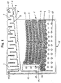
- the cooling unit shown in FIGS. 1 to 3 has an absorber 1 and one Capacitor 2.
- the absorber 1 and the capacitor 2 are made up of two on top of each other laid plates that are laser welded together. It is also possible to separate the capacitor and the absorber from each other to form two plates placed one on top of the other.
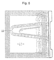
- the absorber 1 has V-shaped lines 3, each meandering are guided one above the other. At the lowest point of each V-shaped line 3, an opening 4 is provided which leads to the adjacent line 3.
- the walls the lines 3 are provided with grooves 5 and 6 to the capillary effects enlarge the walls.
- the grooves are wedge-like with an angle ⁇ of 60 ° and have a depth of 0.3 mm. The distance of two parallel grooves is approximately 1.5 mm.
- a capacitor 2 is arranged above the absorber 1 and has a meandering shape extending first channel 7 and an underlying second channel 8 has. Connections are between the first channel 7 and the second channel 8 9 provided, which serve as a liquid separator. At one end of the first channel 7 there is a connection 10 for a gaseous medium, which is led through the meandering turns. The length of the turns increases over capacitor 2. Accordingly, the second channel 8 formed obliquely downward to the horizontal, see above that excreted liquid is drained down by gravity becomes.
- a liquid collector is provided at the other end of the condenser 2, at its lower end a connection 11 to an evaporator is provided is and at its upper region a connection 112 for a pressure compensation tube is arranged.
- the steam generated in the evaporator is through a connection 12 in the absorber 1 headed.
- the steam flows through the meandering lines 3 and is absorbed by the liquid contained in the absorber 1.
- a precooler 13 for the refrigerant cleaned is arranged at the end of Lines 3 of the absorber 1 .
- Port 112 communicates through that Pressure equalization pipe with connection 12.
- the absorber 1 has a reservoir 17 in its lower region the spacer 18 for spacing the two plates from each other are. At the bottom of the reservoir 17 is a drain 16 for the rich solution provided. In the upper area of the absorber 1 there is a connection 15 arranged for poor solution to be supplied.
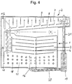
- the cooling unit is shown in the assembled state, the cooling unit is used to cool a room.
- the drain 16 from the reservoir 17 of the absorber 1 leads to a double tube heat exchanger 20, in which heat is added to the rich solution.
- the so warmed up rich solution is passed to a cooker 19 in which the refrigerant is driven out and via a line 21 to the capacitor 2 via the connection 10 is supplied.
- the poor solution generated in the cooker 19 is about Double tube heat exchanger 20 the absorber 1 in an upper area over the Port 15 forwarded.
- the vapor condensed in the condenser 2 becomes the evaporator via the connection 11 22 fed.
- the evaporator 22 is perpendicular to the plate plane of the absorber 1 and the capacitor 2 is formed and passes through a rear wall into a cold room 23.
- the evaporator 22 thus cools the cold room 23, the generated steam being fed to the absorber 1 via the connection 12 becomes.
- the plate-shaped unit is made of absorber 1 and Condenser 2 via connecting elements 24 on the rear wall of the cold room attached.
- the cooling unit is included operated an aqueous ammonia solution, hydrogen being used as the auxiliary gas becomes.
Landscapes
- Engineering & Computer Science (AREA)
- Physics & Mathematics (AREA)
- Mechanical Engineering (AREA)
- Thermal Sciences (AREA)
- General Engineering & Computer Science (AREA)
- Sorption Type Refrigeration Machines (AREA)
- Cookers (AREA)
Applications Claiming Priority (2)
| Application Number | Priority Date | Filing Date | Title |
|---|---|---|---|
| DE19654261A DE19654261A1 (de) | 1996-12-23 | 1996-12-23 | Kühlaggregat |
| DE19654261 | 1996-12-23 |
Publications (1)
| Publication Number | Publication Date |
|---|---|
| EP0851185A2 true EP0851185A2 (fr) | 1998-07-01 |
Family
ID=7816155
Family Applications (1)
| Application Number | Title | Priority Date | Filing Date |
|---|---|---|---|
| EP97121335A Withdrawn EP0851185A2 (fr) | 1996-12-23 | 1997-12-04 | Unité de réfrigération |
Country Status (7)
| Country | Link |
|---|---|
| US (1) | US5921105A (fr) |
| EP (1) | EP0851185A2 (fr) |
| JP (1) | JPH112473A (fr) |
| AU (1) | AU4921097A (fr) |
| CA (1) | CA2224545A1 (fr) |
| DE (1) | DE19654261A1 (fr) |
| NO (1) | NO975650L (fr) |
Families Citing this family (10)
| Publication number | Priority date | Publication date | Assignee | Title |
|---|---|---|---|---|
| DE19958955C2 (de) * | 1999-12-07 | 2002-12-12 | Electrolux Siegen Gmbh | Absorptionskühlanordnung |
| DE102009023929A1 (de) * | 2009-06-04 | 2010-12-09 | Stürzebecher, Wolfgang, Dr. | Absorptionskälteaggregat |
| EP3309474A1 (fr) * | 2016-10-13 | 2018-04-18 | Gadlab Engineering Oy | Système d'unité frigorifique à absorption et système frigorifique à absorption |
| US11933285B2 (en) | 2018-04-23 | 2024-03-19 | Dometic Sweden Ab | Damped mobile compressor |
| DE102018222877B4 (de) | 2018-12-21 | 2020-10-01 | Dometic Sweden Ab | Dachklimaanlageneinheit, Verfahren zur Herstellung, Montage und Installation der Dachklimaanlageneinheit und Fahrzeug mit der Dachklimaanlageneinheit |
| US11951798B2 (en) | 2019-03-18 | 2024-04-09 | Dometic Sweden Ab | Mobile air conditioner |
| WO2020188485A2 (fr) | 2019-03-18 | 2020-09-24 | Dometic Sweden Ab | Climatiseur mobile |
| DE102019212947A1 (de) | 2019-08-28 | 2021-03-04 | Dometic Sweden Ab | Klimaanlage |
| USD1010080S1 (en) | 2020-05-15 | 2024-01-02 | Dometic Sweden Ab | Housing for air conditioning apparatus |
| USD1027143S1 (en) | 2021-07-12 | 2024-05-14 | Dometic Sweden Ab | Housing shroud for an air conditioner |
Citations (2)
| Publication number | Priority date | Publication date | Assignee | Title |
|---|---|---|---|---|
| US3782134A (en) | 1969-05-13 | 1974-01-01 | Westinghouse Electric Corp | Absorption refrigeration system |
| EP0624762A1 (fr) | 1993-05-14 | 1994-11-17 | Aktiebolaget Electrolux | Absorbeur pour machines frigorifiques à absorption |
Family Cites Families (6)
| Publication number | Priority date | Publication date | Assignee | Title |
|---|---|---|---|---|
| US2243903A (en) * | 1937-11-29 | 1941-06-03 | Patentvertungs Gmbh Hermes | Absorption refrigerating apparatus |
| SE354345B (fr) * | 1971-03-18 | 1973-03-05 | Electrolux Ab | |
| US3775996A (en) * | 1972-03-16 | 1973-12-04 | Electrolux Ab | Tiltable air-cooled absorption refrigeration apparatus of the inert gas type |
| US3851497A (en) * | 1973-02-26 | 1974-12-03 | Electrolux Ab | Tiltable air-cooled absorption refrigeration apparatus of the inert gas type |
| SE428723B (sv) * | 1982-01-08 | 1983-07-18 | Electrolux Ab | Tillforselledning till absorbatorer, for absorptionskylapparat med minst tva absorbatorer |
| US5636527A (en) * | 1995-11-15 | 1997-06-10 | The Ohio State University Research Foundation | Enhanced fluid-liquid contact |
-
1996
- 1996-12-23 DE DE19654261A patent/DE19654261A1/de not_active Withdrawn
-
1997
- 1997-12-04 EP EP97121335A patent/EP0851185A2/fr not_active Withdrawn
- 1997-12-05 NO NO975650A patent/NO975650L/no unknown
- 1997-12-09 CA CA002224545A patent/CA2224545A1/fr not_active Abandoned
- 1997-12-18 US US08/993,453 patent/US5921105A/en not_active Expired - Fee Related
- 1997-12-22 JP JP9353678A patent/JPH112473A/ja active Pending
- 1997-12-23 AU AU49210/97A patent/AU4921097A/en not_active Abandoned
Patent Citations (2)
| Publication number | Priority date | Publication date | Assignee | Title |
|---|---|---|---|---|
| US3782134A (en) | 1969-05-13 | 1974-01-01 | Westinghouse Electric Corp | Absorption refrigeration system |
| EP0624762A1 (fr) | 1993-05-14 | 1994-11-17 | Aktiebolaget Electrolux | Absorbeur pour machines frigorifiques à absorption |
Also Published As
| Publication number | Publication date |
|---|---|
| CA2224545A1 (fr) | 1998-06-23 |
| US5921105A (en) | 1999-07-13 |
| AU4921097A (en) | 1998-06-25 |
| NO975650D0 (no) | 1997-12-05 |
| DE19654261A1 (de) | 1998-06-25 |
| JPH112473A (ja) | 1999-01-06 |
| NO975650L (no) | 1998-06-24 |
Similar Documents
| Publication | Publication Date | Title |
|---|---|---|
| DE3856032T3 (de) | Wärmetauscher mit verbesserter Kondensatsammlung | |
| DE3122197C2 (de) | Kondensator | |
| EP1287302B1 (fr) | Condenseur a bain a plusieurs etages | |
| DE69423595T2 (de) | Plattenwärmetauscher | |
| DE69509469T2 (de) | Kühlmittelverdampfer | |
| DE69016119T2 (de) | Wärmerohr. | |
| DE3148375C2 (fr) | ||
| DE59310250T2 (de) | Plattenwärmetauscher | |
| DE69611507T2 (de) | Verflüssiger mit einbezogenem behälter für klimaanlage eines kraftfahrzeuges | |
| DE112005001700T5 (de) | Wärmetauscher | |
| EP0131270A1 (fr) | Absorbeur utilisant une matière solide pour un cycle d'absorption | |
| DE102005013576A1 (de) | Verdampfapparat für einen Kühlkreis | |
| DE112005000797T5 (de) | Wärmetauscher | |
| DE112005001295T5 (de) | Wärmetauscher | |
| DE102005021787A1 (de) | Vorrichtung zur Behandlung des Kältemittels | |
| DE60310992T2 (de) | Hochdruckwärmetauscher | |
| EP1256772A2 (fr) | Echangeur de chaleur | |
| DE2952736C2 (fr) | ||
| EP0851185A2 (fr) | Unité de réfrigération | |
| DE69512876T2 (de) | Wärmeaustauscher | |
| DE69007709T2 (de) | Stapelverdampfer. | |
| DE3502619C2 (fr) | ||
| DE4220823C2 (de) | Heizungswärmetauscher für Personenkraftwagen mit mindestens zwei Teilwärmetauschern | |
| DE10158387B4 (de) | Anordnung zur Kühlung von elektrischen Komponenten | |
| EP2438384A2 (fr) | Tuyau collecteur pour condenseur |
Legal Events
| Date | Code | Title | Description |
|---|---|---|---|
| PUAI | Public reference made under article 153(3) epc to a published international application that has entered the european phase |
Free format text: ORIGINAL CODE: 0009012 |
|
| AK | Designated contracting states |
Kind code of ref document: A2 Designated state(s): AT BE CH DE DK ES FI FR GB GR IE IT LI LU MC NL PT SE |
|
| AX | Request for extension of the european patent |
Free format text: AL;LT;LV;MK;RO;SI |
|
| STAA | Information on the status of an ep patent application or granted ep patent |
Free format text: STATUS: THE APPLICATION IS DEEMED TO BE WITHDRAWN |
|
| 18D | Application deemed to be withdrawn |
Effective date: 20000701 |