EP0850679A2 - Membrane électrolytique solide comprenant un constituant pour l'amélioration des propriétés mécaniques et des constituants poreux pour augmenter l'activité catalytique - Google Patents
Membrane électrolytique solide comprenant un constituant pour l'amélioration des propriétés mécaniques et des constituants poreux pour augmenter l'activité catalytique Download PDFInfo
- Publication number
- EP0850679A2 EP0850679A2 EP97122945A EP97122945A EP0850679A2 EP 0850679 A2 EP0850679 A2 EP 0850679A2 EP 97122945 A EP97122945 A EP 97122945A EP 97122945 A EP97122945 A EP 97122945A EP 0850679 A2 EP0850679 A2 EP 0850679A2
- Authority
- EP
- European Patent Office
- Prior art keywords
- membrane
- constituent
- phase
- ion transport
- matrix material
- Prior art date
- Legal status (The legal status is an assumption and is not a legal conclusion. Google has not performed a legal analysis and makes no representation as to the accuracy of the status listed.)
- Granted
Links
- 239000012528 membrane Substances 0.000 title claims abstract description 125
- 239000000470 constituent Substances 0.000 title claims abstract description 51
- 239000007784 solid electrolyte Substances 0.000 title claims abstract description 21
- 230000002708 enhancing effect Effects 0.000 title claims description 5
- 230000037427 ion transport Effects 0.000 claims abstract description 88
- 239000001301 oxygen Substances 0.000 claims abstract description 63
- 229910052760 oxygen Inorganic materials 0.000 claims abstract description 63
- 238000000576 coating method Methods 0.000 claims abstract description 44
- 239000011248 coating agent Substances 0.000 claims abstract description 42
- 239000011159 matrix material Substances 0.000 claims abstract description 36
- 238000005245 sintering Methods 0.000 claims abstract description 25
- -1 oxygen ions Chemical class 0.000 claims abstract description 20
- 230000003197 catalytic effect Effects 0.000 claims abstract description 18
- 150000002500 ions Chemical class 0.000 claims abstract description 16
- 238000006557 surface reaction Methods 0.000 claims abstract description 9
- 239000000463 material Substances 0.000 claims description 60
- 239000011533 mixed conductor Substances 0.000 claims description 28
- 239000000203 mixture Substances 0.000 claims description 26
- XEEYBQQBJWHFJM-UHFFFAOYSA-N Iron Chemical compound [Fe] XEEYBQQBJWHFJM-UHFFFAOYSA-N 0.000 claims description 16
- KDLHZDBZIXYQEI-UHFFFAOYSA-N Palladium Chemical compound [Pd] KDLHZDBZIXYQEI-UHFFFAOYSA-N 0.000 claims description 13
- 229910052751 metal Inorganic materials 0.000 claims description 11
- 239000002184 metal Substances 0.000 claims description 11
- BQCADISMDOOEFD-UHFFFAOYSA-N Silver Chemical compound [Ag] BQCADISMDOOEFD-UHFFFAOYSA-N 0.000 claims description 8
- 229910052709 silver Inorganic materials 0.000 claims description 8
- 239000004332 silver Substances 0.000 claims description 8
- 229910052763 palladium Inorganic materials 0.000 claims description 7
- PXHVJJICTQNCMI-UHFFFAOYSA-N Nickel Chemical compound [Ni] PXHVJJICTQNCMI-UHFFFAOYSA-N 0.000 claims description 5
- BASFCYQUMIYNBI-UHFFFAOYSA-N platinum Chemical compound [Pt] BASFCYQUMIYNBI-UHFFFAOYSA-N 0.000 claims description 4
- 239000010949 copper Substances 0.000 claims description 3
- PCHJSUWPFVWCPO-UHFFFAOYSA-N gold Chemical compound [Au] PCHJSUWPFVWCPO-UHFFFAOYSA-N 0.000 claims description 3
- 229910052737 gold Inorganic materials 0.000 claims description 3
- 239000010931 gold Substances 0.000 claims description 3
- 229910052747 lanthanoid Inorganic materials 0.000 claims description 3
- 150000002602 lanthanoids Chemical class 0.000 claims description 3
- 229910052759 nickel Inorganic materials 0.000 claims description 3
- 238000005325 percolation Methods 0.000 claims description 3
- 229910052715 tantalum Inorganic materials 0.000 claims description 3
- GUVRBAGPIYLISA-UHFFFAOYSA-N tantalum atom Chemical compound [Ta] GUVRBAGPIYLISA-UHFFFAOYSA-N 0.000 claims description 3
- 239000010936 titanium Substances 0.000 claims description 3
- 229910052719 titanium Inorganic materials 0.000 claims description 3
- KJTLSVCANCCWHF-UHFFFAOYSA-N Ruthenium Chemical compound [Ru] KJTLSVCANCCWHF-UHFFFAOYSA-N 0.000 claims description 2
- RTAQQCXQSZGOHL-UHFFFAOYSA-N Titanium Chemical compound [Ti] RTAQQCXQSZGOHL-UHFFFAOYSA-N 0.000 claims description 2
- 229910052804 chromium Inorganic materials 0.000 claims description 2
- 239000011651 chromium Substances 0.000 claims description 2
- 229910052802 copper Inorganic materials 0.000 claims description 2
- 239000007769 metal material Substances 0.000 claims description 2
- 229910052697 platinum Inorganic materials 0.000 claims description 2
- 229910052703 rhodium Inorganic materials 0.000 claims description 2
- 239000010948 rhodium Substances 0.000 claims description 2
- MHOVAHRLVXNVSD-UHFFFAOYSA-N rhodium atom Chemical compound [Rh] MHOVAHRLVXNVSD-UHFFFAOYSA-N 0.000 claims description 2
- 229910052707 ruthenium Inorganic materials 0.000 claims description 2
- WFKWXMTUELFFGS-UHFFFAOYSA-N tungsten Chemical compound [W] WFKWXMTUELFFGS-UHFFFAOYSA-N 0.000 claims description 2
- 229910052721 tungsten Inorganic materials 0.000 claims description 2
- 239000010937 tungsten Substances 0.000 claims description 2
- 229910052720 vanadium Inorganic materials 0.000 claims description 2
- VYZAMTAEIAYCRO-UHFFFAOYSA-N Chromium Chemical compound [Cr] VYZAMTAEIAYCRO-UHFFFAOYSA-N 0.000 claims 1
- RYGMFSIKBFXOCR-UHFFFAOYSA-N Copper Chemical compound [Cu] RYGMFSIKBFXOCR-UHFFFAOYSA-N 0.000 claims 1
- 229920000914 Metallic fiber Polymers 0.000 claims 1
- ZOKXTWBITQBERF-UHFFFAOYSA-N Molybdenum Chemical compound [Mo] ZOKXTWBITQBERF-UHFFFAOYSA-N 0.000 claims 1
- XUIMIQQOPSSXEZ-UHFFFAOYSA-N Silicon Chemical compound [Si] XUIMIQQOPSSXEZ-UHFFFAOYSA-N 0.000 claims 1
- QCWXUUIWCKQGHC-UHFFFAOYSA-N Zirconium Chemical compound [Zr] QCWXUUIWCKQGHC-UHFFFAOYSA-N 0.000 claims 1
- 229910052782 aluminium Inorganic materials 0.000 claims 1
- XAGFODPZIPBFFR-UHFFFAOYSA-N aluminium Chemical compound [Al] XAGFODPZIPBFFR-UHFFFAOYSA-N 0.000 claims 1
- 229910017052 cobalt Inorganic materials 0.000 claims 1
- 239000010941 cobalt Substances 0.000 claims 1
- GUTLYIVDDKVIGB-UHFFFAOYSA-N cobalt atom Chemical compound [Co] GUTLYIVDDKVIGB-UHFFFAOYSA-N 0.000 claims 1
- 229910052742 iron Inorganic materials 0.000 claims 1
- WPBNNNQJVZRUHP-UHFFFAOYSA-L manganese(2+);methyl n-[[2-(methoxycarbonylcarbamothioylamino)phenyl]carbamothioyl]carbamate;n-[2-(sulfidocarbothioylamino)ethyl]carbamodithioate Chemical compound [Mn+2].[S-]C(=S)NCCNC([S-])=S.COC(=O)NC(=S)NC1=CC=CC=C1NC(=S)NC(=O)OC WPBNNNQJVZRUHP-UHFFFAOYSA-L 0.000 claims 1
- 229910052750 molybdenum Inorganic materials 0.000 claims 1
- 239000011733 molybdenum Substances 0.000 claims 1
- 229910052758 niobium Inorganic materials 0.000 claims 1
- 239000010955 niobium Substances 0.000 claims 1
- GUCVJGMIXFAOAE-UHFFFAOYSA-N niobium atom Chemical compound [Nb] GUCVJGMIXFAOAE-UHFFFAOYSA-N 0.000 claims 1
- 229910052710 silicon Inorganic materials 0.000 claims 1
- 239000010703 silicon Substances 0.000 claims 1
- LEONUFNNVUYDNQ-UHFFFAOYSA-N vanadium atom Chemical compound [V] LEONUFNNVUYDNQ-UHFFFAOYSA-N 0.000 claims 1
- 229910052727 yttrium Inorganic materials 0.000 claims 1
- VWQVUPCCIRVNHF-UHFFFAOYSA-N yttrium atom Chemical compound [Y] VWQVUPCCIRVNHF-UHFFFAOYSA-N 0.000 claims 1
- 229910052726 zirconium Inorganic materials 0.000 claims 1
- QVGXLLKOCUKJST-UHFFFAOYSA-N atomic oxygen Chemical compound [O] QVGXLLKOCUKJST-UHFFFAOYSA-N 0.000 description 44
- 230000004907 flux Effects 0.000 description 32
- 239000010410 layer Substances 0.000 description 28
- 230000032258 transport Effects 0.000 description 24
- 239000007789 gas Substances 0.000 description 20
- 238000012360 testing method Methods 0.000 description 19
- 239000002131 composite material Substances 0.000 description 18
- 230000009977 dual effect Effects 0.000 description 17
- 238000000034 method Methods 0.000 description 17
- 239000000919 ceramic Substances 0.000 description 16
- MCMNRKCIXSYSNV-UHFFFAOYSA-N Zirconium dioxide Chemical group O=[Zr]=O MCMNRKCIXSYSNV-UHFFFAOYSA-N 0.000 description 14
- 238000010926 purge Methods 0.000 description 14
- 239000011777 magnesium Substances 0.000 description 13
- 229910045601 alloy Inorganic materials 0.000 description 12
- 239000000956 alloy Substances 0.000 description 12
- 230000035882 stress Effects 0.000 description 12
- 239000011247 coating layer Substances 0.000 description 10
- 238000004519 manufacturing process Methods 0.000 description 10
- VNWKTOKETHGBQD-UHFFFAOYSA-N methane Chemical compound C VNWKTOKETHGBQD-UHFFFAOYSA-N 0.000 description 10
- 239000012298 atmosphere Substances 0.000 description 9
- 238000000151 deposition Methods 0.000 description 8
- 229910001316 Ag alloy Inorganic materials 0.000 description 7
- 229910001252 Pd alloy Inorganic materials 0.000 description 7
- 238000001816 cooling Methods 0.000 description 7
- 239000003792 electrolyte Substances 0.000 description 7
- 230000001965 increasing effect Effects 0.000 description 7
- 239000000047 product Substances 0.000 description 7
- KFZMGEQAYNKOFK-UHFFFAOYSA-N Isopropanol Chemical compound CC(C)O KFZMGEQAYNKOFK-UHFFFAOYSA-N 0.000 description 6
- CPLXHLVBOLITMK-UHFFFAOYSA-N Magnesium oxide Chemical compound [Mg]=O CPLXHLVBOLITMK-UHFFFAOYSA-N 0.000 description 6
- 239000004020 conductor Substances 0.000 description 6
- 239000008187 granular material Substances 0.000 description 6
- 238000012545 processing Methods 0.000 description 6
- 239000007787 solid Substances 0.000 description 6
- 230000006399 behavior Effects 0.000 description 5
- 230000008859 change Effects 0.000 description 5
- 238000005516 engineering process Methods 0.000 description 5
- 239000002002 slurry Substances 0.000 description 5
- IJGRMHOSHXDMSA-UHFFFAOYSA-N Atomic nitrogen Chemical compound N#N IJGRMHOSHXDMSA-UHFFFAOYSA-N 0.000 description 4
- 239000011575 calcium Substances 0.000 description 4
- CETPSERCERDGAM-UHFFFAOYSA-N ceric oxide Chemical compound O=[Ce]=O CETPSERCERDGAM-UHFFFAOYSA-N 0.000 description 4
- 229910000422 cerium(IV) oxide Inorganic materials 0.000 description 4
- 238000003618 dip coating Methods 0.000 description 4
- 239000000446 fuel Substances 0.000 description 4
- 238000010438 heat treatment Methods 0.000 description 4
- 239000001307 helium Substances 0.000 description 4
- 229910052734 helium Inorganic materials 0.000 description 4
- SWQJXJOGLNCZEY-UHFFFAOYSA-N helium atom Chemical compound [He] SWQJXJOGLNCZEY-UHFFFAOYSA-N 0.000 description 4
- 239000010416 ion conductor Substances 0.000 description 4
- 239000000843 powder Substances 0.000 description 4
- 241000894007 species Species 0.000 description 4
- 238000001228 spectrum Methods 0.000 description 4
- 239000000126 substance Substances 0.000 description 4
- 238000002441 X-ray diffraction Methods 0.000 description 3
- 229910052791 calcium Inorganic materials 0.000 description 3
- 230000032798 delamination Effects 0.000 description 3
- 230000000694 effects Effects 0.000 description 3
- 239000011532 electronic conductor Substances 0.000 description 3
- 239000010408 film Substances 0.000 description 3
- 239000008246 gaseous mixture Substances 0.000 description 3
- 239000000395 magnesium oxide Substances 0.000 description 3
- 229910044991 metal oxide Inorganic materials 0.000 description 3
- 230000004048 modification Effects 0.000 description 3
- 238000012986 modification Methods 0.000 description 3
- 238000000926 separation method Methods 0.000 description 3
- 229910052712 strontium Inorganic materials 0.000 description 3
- 230000008646 thermal stress Effects 0.000 description 3
- OKTJSMMVPCPJKN-UHFFFAOYSA-N Carbon Chemical compound [C] OKTJSMMVPCPJKN-UHFFFAOYSA-N 0.000 description 2
- GWEVSGVZZGPLCZ-UHFFFAOYSA-N Titan oxide Chemical compound O=[Ti]=O GWEVSGVZZGPLCZ-UHFFFAOYSA-N 0.000 description 2
- PNEYBMLMFCGWSK-UHFFFAOYSA-N aluminium oxide Inorganic materials [O-2].[O-2].[O-2].[Al+3].[Al+3] PNEYBMLMFCGWSK-UHFFFAOYSA-N 0.000 description 2
- 238000004458 analytical method Methods 0.000 description 2
- 239000011230 binding agent Substances 0.000 description 2
- 238000005229 chemical vapour deposition Methods 0.000 description 2
- 239000008199 coating composition Substances 0.000 description 2
- RKTYLMNFRDHKIL-UHFFFAOYSA-N copper;5,10,15,20-tetraphenylporphyrin-22,24-diide Chemical compound [Cu+2].C1=CC(C(=C2C=CC([N-]2)=C(C=2C=CC=CC=2)C=2C=CC(N=2)=C(C=2C=CC=CC=2)C2=CC=C3[N-]2)C=2C=CC=CC=2)=NC1=C3C1=CC=CC=C1 RKTYLMNFRDHKIL-UHFFFAOYSA-N 0.000 description 2
- 230000008021 deposition Effects 0.000 description 2
- 238000001035 drying Methods 0.000 description 2
- 239000000835 fiber Substances 0.000 description 2
- 239000001257 hydrogen Substances 0.000 description 2
- 229910052739 hydrogen Inorganic materials 0.000 description 2
- 239000011261 inert gas Substances 0.000 description 2
- 230000003993 interaction Effects 0.000 description 2
- 150000002739 metals Chemical class 0.000 description 2
- 238000002156 mixing Methods 0.000 description 2
- 229910000480 nickel oxide Inorganic materials 0.000 description 2
- 229910052757 nitrogen Inorganic materials 0.000 description 2
- GNRSAWUEBMWBQH-UHFFFAOYSA-N oxonickel Chemical compound [Ni]=O GNRSAWUEBMWBQH-UHFFFAOYSA-N 0.000 description 2
- 230000000704 physical effect Effects 0.000 description 2
- 238000005240 physical vapour deposition Methods 0.000 description 2
- 238000013001 point bending Methods 0.000 description 2
- 229920002037 poly(vinyl butyral) polymer Polymers 0.000 description 2
- 238000003825 pressing Methods 0.000 description 2
- 238000009790 rate-determining step (RDS) Methods 0.000 description 2
- 238000001878 scanning electron micrograph Methods 0.000 description 2
- 238000004611 spectroscopical analysis Methods 0.000 description 2
- 238000004528 spin coating Methods 0.000 description 2
- 238000009987 spinning Methods 0.000 description 2
- 239000007921 spray Substances 0.000 description 2
- 239000010409 thin film Substances 0.000 description 2
- OGIDPMRJRNCKJF-UHFFFAOYSA-N titanium oxide Inorganic materials [Ti]=O OGIDPMRJRNCKJF-UHFFFAOYSA-N 0.000 description 2
- 230000009466 transformation Effects 0.000 description 2
- 238000000844 transformation Methods 0.000 description 2
- XLYOFNOQVPJJNP-UHFFFAOYSA-N water Substances O XLYOFNOQVPJJNP-UHFFFAOYSA-N 0.000 description 2
- OYPRJOBELJOOCE-UHFFFAOYSA-N Calcium Chemical compound [Ca] OYPRJOBELJOOCE-UHFFFAOYSA-N 0.000 description 1
- ODINCKMPIJJUCX-UHFFFAOYSA-N Calcium oxide Chemical compound [Ca]=O ODINCKMPIJJUCX-UHFFFAOYSA-N 0.000 description 1
- 229910002451 CoOx Inorganic materials 0.000 description 1
- MYMOFIZGZYHOMD-UHFFFAOYSA-N Dioxygen Chemical compound O=O MYMOFIZGZYHOMD-UHFFFAOYSA-N 0.000 description 1
- 229910015189 FeOx Inorganic materials 0.000 description 1
- UFHFLCQGNIYNRP-UHFFFAOYSA-N Hydrogen Chemical compound [H][H] UFHFLCQGNIYNRP-UHFFFAOYSA-N 0.000 description 1
- 229910002273 La1–xSrxCoO3 Inorganic materials 0.000 description 1
- FYYHWMGAXLPEAU-UHFFFAOYSA-N Magnesium Chemical compound [Mg] FYYHWMGAXLPEAU-UHFFFAOYSA-N 0.000 description 1
- 229910000792 Monel Inorganic materials 0.000 description 1
- 241000968352 Scandia <hydrozoan> Species 0.000 description 1
- OBOYOXRQUWVUFU-UHFFFAOYSA-N [O-2].[Ti+4].[Nb+5] Chemical compound [O-2].[Ti+4].[Nb+5] OBOYOXRQUWVUFU-UHFFFAOYSA-N 0.000 description 1
- 230000004913 activation Effects 0.000 description 1
- 230000002411 adverse Effects 0.000 description 1
- 229910052784 alkaline earth metal Inorganic materials 0.000 description 1
- 150000001342 alkaline earth metals Chemical class 0.000 description 1
- 239000010425 asbestos Substances 0.000 description 1
- 229910052788 barium Inorganic materials 0.000 description 1
- DSAJWYNOEDNPEQ-UHFFFAOYSA-N barium atom Chemical compound [Ba] DSAJWYNOEDNPEQ-UHFFFAOYSA-N 0.000 description 1
- 230000008901 benefit Effects 0.000 description 1
- 230000015572 biosynthetic process Effects 0.000 description 1
- 229910000416 bismuth oxide Inorganic materials 0.000 description 1
- 239000000292 calcium oxide Substances 0.000 description 1
- 235000012255 calcium oxide Nutrition 0.000 description 1
- 230000015556 catabolic process Effects 0.000 description 1
- 239000003054 catalyst Substances 0.000 description 1
- 239000010406 cathode material Substances 0.000 description 1
- 238000006243 chemical reaction Methods 0.000 description 1
- 238000009694 cold isostatic pressing Methods 0.000 description 1
- 150000001875 compounds Chemical class 0.000 description 1
- 238000004320 controlled atmosphere Methods 0.000 description 1
- 238000005336 cracking Methods 0.000 description 1
- 239000013078 crystal Substances 0.000 description 1
- 230000007423 decrease Effects 0.000 description 1
- 238000006731 degradation reaction Methods 0.000 description 1
- 230000002939 deleterious effect Effects 0.000 description 1
- 230000001419 dependent effect Effects 0.000 description 1
- 229910003460 diamond Inorganic materials 0.000 description 1
- 239000010432 diamond Substances 0.000 description 1
- TYIXMATWDRGMPF-UHFFFAOYSA-N dibismuth;oxygen(2-) Chemical compound [O-2].[O-2].[O-2].[Bi+3].[Bi+3] TYIXMATWDRGMPF-UHFFFAOYSA-N 0.000 description 1
- 238000007598 dipping method Methods 0.000 description 1
- 239000002270 dispersing agent Substances 0.000 description 1
- 238000010494 dissociation reaction Methods 0.000 description 1
- 230000005593 dissociations Effects 0.000 description 1
- 238000002474 experimental method Methods 0.000 description 1
- 238000004817 gas chromatography Methods 0.000 description 1
- 239000011521 glass Substances 0.000 description 1
- 239000010440 gypsum Substances 0.000 description 1
- 229910052602 gypsum Inorganic materials 0.000 description 1
- 229910000856 hastalloy Inorganic materials 0.000 description 1
- 150000002431 hydrogen Chemical class 0.000 description 1
- 229910001026 inconel Inorganic materials 0.000 description 1
- KILFUJHTZJZRLZ-UHFFFAOYSA-N indium(3+) oxygen(2-) praseodymium(3+) Chemical compound [O-2].[In+3].[Pr+3].[O-2].[O-2] KILFUJHTZJZRLZ-UHFFFAOYSA-N 0.000 description 1
- 238000000608 laser ablation Methods 0.000 description 1
- 239000012705 liquid precursor Substances 0.000 description 1
- 229910052749 magnesium Inorganic materials 0.000 description 1
- 229910052748 manganese Inorganic materials 0.000 description 1
- 229910000473 manganese(VI) oxide Inorganic materials 0.000 description 1
- 230000007246 mechanism Effects 0.000 description 1
- 150000004706 metal oxides Chemical class 0.000 description 1
- 239000010445 mica Substances 0.000 description 1
- 229910052618 mica group Inorganic materials 0.000 description 1
- 230000007935 neutral effect Effects 0.000 description 1
- 239000012299 nitrogen atmosphere Substances 0.000 description 1
- 239000012811 non-conductive material Substances 0.000 description 1
- QGLKJKCYBOYXKC-UHFFFAOYSA-N nonaoxidotritungsten Chemical compound O=[W]1(=O)O[W](=O)(=O)O[W](=O)(=O)O1 QGLKJKCYBOYXKC-UHFFFAOYSA-N 0.000 description 1
- 230000003287 optical effect Effects 0.000 description 1
- 238000007254 oxidation reaction Methods 0.000 description 1
- AHKZTVQIVOEVFO-UHFFFAOYSA-N oxide(2-) Chemical compound [O-2] AHKZTVQIVOEVFO-UHFFFAOYSA-N 0.000 description 1
- HJGMWXTVGKLUAQ-UHFFFAOYSA-N oxygen(2-);scandium(3+) Chemical compound [O-2].[O-2].[O-2].[Sc+3].[Sc+3] HJGMWXTVGKLUAQ-UHFFFAOYSA-N 0.000 description 1
- BPUBBGLMJRNUCC-UHFFFAOYSA-N oxygen(2-);tantalum(5+) Chemical compound [O-2].[O-2].[O-2].[O-2].[O-2].[Ta+5].[Ta+5] BPUBBGLMJRNUCC-UHFFFAOYSA-N 0.000 description 1
- 230000000737 periodic effect Effects 0.000 description 1
- 239000012466 permeate Substances 0.000 description 1
- 230000008569 process Effects 0.000 description 1
- 230000005855 radiation Effects 0.000 description 1
- 230000009467 reduction Effects 0.000 description 1
- 230000002787 reinforcement Effects 0.000 description 1
- 229910052895 riebeckite Inorganic materials 0.000 description 1
- 238000013341 scale-up Methods 0.000 description 1
- 230000035945 sensitivity Effects 0.000 description 1
- 238000007569 slipcasting Methods 0.000 description 1
- 238000004544 sputter deposition Methods 0.000 description 1
- CIOAGBVUUVVLOB-UHFFFAOYSA-N strontium atom Chemical compound [Sr] CIOAGBVUUVVLOB-UHFFFAOYSA-N 0.000 description 1
- 239000002344 surface layer Substances 0.000 description 1
- 238000010301 surface-oxidation reaction Methods 0.000 description 1
- 229910001936 tantalum oxide Inorganic materials 0.000 description 1
- 238000009864 tensile test Methods 0.000 description 1
- 238000005382 thermal cycling Methods 0.000 description 1
- 230000001052 transient effect Effects 0.000 description 1
- 230000007704 transition Effects 0.000 description 1
- 229910052723 transition metal Inorganic materials 0.000 description 1
- 150000003624 transition metals Chemical class 0.000 description 1
- 229910001930 tungsten oxide Inorganic materials 0.000 description 1
- 238000003826 uniaxial pressing Methods 0.000 description 1
- 238000007740 vapor deposition Methods 0.000 description 1
- RUDFQVOCFDJEEF-UHFFFAOYSA-N yttrium(III) oxide Inorganic materials [O-2].[O-2].[O-2].[Y+3].[Y+3] RUDFQVOCFDJEEF-UHFFFAOYSA-N 0.000 description 1
Images


Classifications
-
- B—PERFORMING OPERATIONS; TRANSPORTING
- B01—PHYSICAL OR CHEMICAL PROCESSES OR APPARATUS IN GENERAL
- B01D—SEPARATION
- B01D61/00—Processes of separation using semi-permeable membranes, e.g. dialysis, osmosis or ultrafiltration; Apparatus, accessories or auxiliary operations specially adapted therefor
- B01D61/42—Electrodialysis; Electro-osmosis ; Electro-ultrafiltration; Membrane capacitive deionization
- B01D61/44—Ion-selective electrodialysis
- B01D61/46—Apparatus therefor
-
- B—PERFORMING OPERATIONS; TRANSPORTING
- B01—PHYSICAL OR CHEMICAL PROCESSES OR APPARATUS IN GENERAL
- B01D—SEPARATION
- B01D67/00—Processes specially adapted for manufacturing semi-permeable membranes for separation processes or apparatus
- B01D67/0039—Inorganic membrane manufacture
- B01D67/0046—Inorganic membrane manufacture by slurry techniques, e.g. die or slip-casting
-
- B—PERFORMING OPERATIONS; TRANSPORTING
- B01—PHYSICAL OR CHEMICAL PROCESSES OR APPARATUS IN GENERAL
- B01D—SEPARATION
- B01D69/00—Semi-permeable membranes for separation processes or apparatus characterised by their form, structure or properties; Manufacturing processes specially adapted therefor
- B01D69/10—Supported membranes; Membrane supports
-
- B—PERFORMING OPERATIONS; TRANSPORTING
- B01—PHYSICAL OR CHEMICAL PROCESSES OR APPARATUS IN GENERAL
- B01D—SEPARATION
- B01D69/00—Semi-permeable membranes for separation processes or apparatus characterised by their form, structure or properties; Manufacturing processes specially adapted therefor
- B01D69/12—Composite membranes; Ultra-thin membranes
- B01D69/1213—Laminated layers
-
- B—PERFORMING OPERATIONS; TRANSPORTING
- B01—PHYSICAL OR CHEMICAL PROCESSES OR APPARATUS IN GENERAL
- B01D—SEPARATION
- B01D69/00—Semi-permeable membranes for separation processes or apparatus characterised by their form, structure or properties; Manufacturing processes specially adapted therefor
- B01D69/12—Composite membranes; Ultra-thin membranes
- B01D69/1216—Three or more layers
-
- B—PERFORMING OPERATIONS; TRANSPORTING
- B01—PHYSICAL OR CHEMICAL PROCESSES OR APPARATUS IN GENERAL
- B01D—SEPARATION
- B01D69/00—Semi-permeable membranes for separation processes or apparatus characterised by their form, structure or properties; Manufacturing processes specially adapted therefor
- B01D69/14—Dynamic membranes
- B01D69/141—Heterogeneous membranes, e.g. containing dispersed material; Mixed matrix membranes
- B01D69/1411—Heterogeneous membranes, e.g. containing dispersed material; Mixed matrix membranes containing dispersed material in a continuous matrix
-
- B—PERFORMING OPERATIONS; TRANSPORTING
- B01—PHYSICAL OR CHEMICAL PROCESSES OR APPARATUS IN GENERAL
- B01D—SEPARATION
- B01D71/00—Semi-permeable membranes for separation processes or apparatus characterised by the material; Manufacturing processes specially adapted therefor
- B01D71/02—Inorganic material
- B01D71/0213—Silicon
-
- B—PERFORMING OPERATIONS; TRANSPORTING
- B01—PHYSICAL OR CHEMICAL PROCESSES OR APPARATUS IN GENERAL
- B01D—SEPARATION
- B01D71/00—Semi-permeable membranes for separation processes or apparatus characterised by the material; Manufacturing processes specially adapted therefor
- B01D71/02—Inorganic material
- B01D71/022—Metals
-
- B—PERFORMING OPERATIONS; TRANSPORTING
- B01—PHYSICAL OR CHEMICAL PROCESSES OR APPARATUS IN GENERAL
- B01D—SEPARATION
- B01D71/00—Semi-permeable membranes for separation processes or apparatus characterised by the material; Manufacturing processes specially adapted therefor
- B01D71/02—Inorganic material
- B01D71/024—Oxides
- B01D71/0271—Perovskites
-
- B—PERFORMING OPERATIONS; TRANSPORTING
- B01—PHYSICAL OR CHEMICAL PROCESSES OR APPARATUS IN GENERAL
- B01J—CHEMICAL OR PHYSICAL PROCESSES, e.g. CATALYSIS OR COLLOID CHEMISTRY; THEIR RELEVANT APPARATUS
- B01J35/00—Catalysts, in general, characterised by their form or physical properties
- B01J35/19—Catalysts containing parts with different compositions
-
- B—PERFORMING OPERATIONS; TRANSPORTING
- B01—PHYSICAL OR CHEMICAL PROCESSES OR APPARATUS IN GENERAL
- B01J—CHEMICAL OR PHYSICAL PROCESSES, e.g. CATALYSIS OR COLLOID CHEMISTRY; THEIR RELEVANT APPARATUS
- B01J35/00—Catalysts, in general, characterised by their form or physical properties
- B01J35/30—Catalysts, in general, characterised by their form or physical properties characterised by their physical properties
- B01J35/33—Electric or magnetic properties
-
- C—CHEMISTRY; METALLURGY
- C01—INORGANIC CHEMISTRY
- C01B—NON-METALLIC ELEMENTS; COMPOUNDS THEREOF; METALLOIDS OR COMPOUNDS THEREOF NOT COVERED BY SUBCLASS C01C
- C01B13/00—Oxygen; Ozone; Oxides or hydroxides in general
- C01B13/02—Preparation of oxygen
- C01B13/0229—Purification or separation processes
- C01B13/0248—Physical processing only
- C01B13/0251—Physical processing only by making use of membranes
- C01B13/0255—Physical processing only by making use of membranes characterised by the type of membrane
-
- B—PERFORMING OPERATIONS; TRANSPORTING
- B01—PHYSICAL OR CHEMICAL PROCESSES OR APPARATUS IN GENERAL
- B01D—SEPARATION
- B01D2323/00—Details relating to membrane preparation
- B01D2323/12—Specific ratios of components used
-
- B—PERFORMING OPERATIONS; TRANSPORTING
- B01—PHYSICAL OR CHEMICAL PROCESSES OR APPARATUS IN GENERAL
- B01D—SEPARATION
- B01D2325/00—Details relating to properties of membranes
- B01D2325/26—Electrical properties
-
- C—CHEMISTRY; METALLURGY
- C01—INORGANIC CHEMISTRY
- C01B—NON-METALLIC ELEMENTS; COMPOUNDS THEREOF; METALLOIDS OR COMPOUNDS THEREOF NOT COVERED BY SUBCLASS C01C
- C01B2210/00—Purification or separation of specific gases
- C01B2210/0043—Impurity removed
- C01B2210/0046—Nitrogen
Definitions
- This invention relates to compositions of solid electrolyte ion transport membranes and more particularly to such membranes having one or more constituents which enhance mechanical properties, catalytic properties and/or sintering behavior of the membranes.
- Solid electrolyte ion transport membranes have significant potential for the separation of oxygen from gas streams containing oxygen.
- mixed conductor materials that conduct both oxygen ions and electrons and which can hence be operated in a pressure driven mode without the use of external electrodes.
- Composite ceramic mixed conductor membranes comprised of multi-phase mixtures of an electronically-conductive material and an oxygen ion conductive material are disclosed by T. J. Mazanec et al. in U.S. Patent No. 5,306,411 for electrochemical reactors and partial oxidation reactions.
- M. Liu et al. disclose in U.S. Patent No. 5,478,444 composite mixed conductor materials containing oxygen-ion-conducting materials such as bismuth oxide and electronically conductive materials.
- True mixed conductors exemplified by perovskites such as La .2 Sr .8 CoO x , La .2 Sr .8 FeO x , La .2 Sr .8 Fe .8 Co .1 Cr .1 O x and others, are materials that possess intrinsic conductivity for both electrons and ions. Some of these materials possess among the highest oxygen ion conductivity known and also rapid surface exchange kinetics.
- perovskite tubes has required complex, carefully controlled process steps sometimes involving a sophisticated, controlled atmosphere sintering process. This increases the cost and complexity of fabrication and could result in problems during transient operation of the manufactured elements involving temperature, atmospheric or compositional changes.
- the use of the composite mixed conductors in the prior art is mostly confined to materials comprising multi-phase mixtures of oxygen ion conductors and electronic conductors.
- the primary objective in the prior art was to introduce electronic conductivity into the ionic conductor. In general, this requires the electronically conductive second phase to be present in greater than 30% to 35% by volume when randomly distributed to enable operation above the percolation limit.
- the '542 patent describes ceramic/metallic materials having a predominantly electronic conducting metal phase providing enhanced mechanical properties compared to a predominantly ionic conducting ceramic phase alone.
- Composite bulk superconducting materials have been synthesized to achieve desirable physical properties and high T c superconducting characteristics.
- Wong et al. in U.S. Patent No. 5,470,821 describe composite bulk superconducting materials with continuous superconducting ceramic and elemental metal matrices. The elemental metal is situated within the interstices between the crystalline grains to increase transport current density.
- Oxygen transport is driven by the partial pressure of the oxygen in the gas streams.
- the Nernst potential is developed internally, and drives the flux of oxygen vacancies against the ionic resistance of the electrolyte as disclosed in commonly assigned U.S. Patent No. 5,547,494 by Prasad et al. entitled “Staged Electrolyte Membrane", which is incorporated herein by reference.
- thin electrolyte films are desirable because the ideal oxygen flux is inversely proportional to their thickness.
- thinner films lead to higher oxygen fluxes, reduced area, lower operating temperatures and lower oxygen pressure differentials across the electrolytes.
- a reactive gas such as methane or hydrogen
- the oxygen activity on the anode side reduces significantly, thus leading to higher oxygen flux across the membrane.
- the surface resistance to transport become more pronounced and ultimately dominate the overall resistance to transport. Surface resistance arise from various mechanisms involved in converting an oxygen molecule in the gas phase to oxygen ions in the crystal lattice and vice versa. Even for dense ion transport membranes, surface kinetics on the cathode or the anode side may limit the oxygen flux across the membrane.
- U.S. Patent No. 4,791,079 discloses catalytic ceramic membranes consisting of two layers, an impervious mixed ion and electronic conducting ceramic layer and a porous catalyst-containing ion conducting ceramic layer.
- the preferred composition for the porous ceramic layer is zirconia stabilized with approximately 8 to 15 mole percent calcia, yttria, scandia, magnesia, and/or mixtures thereof.
- U.S. Patent No. 5,240,480 discloses multi-layer composite solid state membranes, comprising a multicomponent metallic oxide porous layer and dense layer, which are capable of separating oxygen from oxygen-containing gaseous mixtures at elevated temperature.
- U.S. Patent No. 5,569,633 discloses surface catalyzed multi-layer ceramic membranes consisting of a dense mixed conducting multicomponent metallic oxide layer, and a catalyzed metal or metal oxide coating on the feed (air) side to enhance the oxygen flux. Catalytic coating on both sides did not enhance the oxygen flux.
- Yet another object of this invention is to provide such a membrane which does not require a special atmosphere during its processing or operation.
- a still further object of this invention is to provide such a membrane which adapts to changes in temperature and atmosphere.
- This invention comprises a solid electrolyte ion transport membrane having a matrix material which conducts at least one type of ion, preferably oxygen ions, and at least one constituent which is physically distinct from the matrix material and which enhances the mechanical properties, the catalytic properties, and/or the sintering behavior of the matrix material.
- the constituent is present in a manner which precludes continuous electronic conductivity through the constituent across the membrane.
- the matrix material is a mixed conductor which exhibits both electronic and oxygen ion conductivity.
- the constituent is preferably a metal such as silver, palladium, or a mixture thereof. In other embodiments, the constituent is a ceramic or other electrically nonconductive material.
- This invention also comprises a solid electrolyte ion transport membrane composite for separating a gaseous species from a gaseous mixture in which the composite has a dense matrix material and a porous coating.
- the dense membrane has a first surface and a second surface, and is comprised of a matrix material which conducts at least one type of ions, and at least one membrane constituent which is physically distinguishable from the matrix material, enhances at least one of the mechanical properties, catalytic properties and sintering behaviors of the matrix material, and is present in a manner which precludes continuous electronic conductivity through the membrane constituent across the membrane.
- the porous coating is disposed on at least one of the first and second surfaces of the membrane to enhance the rate of surface reactions involving the gaseous species.
- the term "dual phase” refers to the combination of a phase which conducts at least one type of ion, and a phase comprising the constituent.
- This invention may be accomplished by a solid electrolyte ion transport membrane comprising a matrix material which conducts at least type of ion, preferably oxygen ions, and at least one constituent which is physically distinct from the matrix material and which enhances the mechanical properties, the catalytic properties and/or the sintering behavior of the matrix material.
- the constituent is present a manner which precludes continuous electronic conductivity through the constituent across the membrane.
- the invention thus relates to a multi-phase, composite material comprised preferably of a first mixed conductor phase such as a perovskite and a second constituent phase which can prevent microcracking during fabrication, eliminate special atmospheric control during processing and operation, and improve the mechanical properties, thermal cyclability, atmosphere cyclability and/or surface exchange rates over that of the mixed conductor phase alone.
- a first mixed conductor phase such as a perovskite
- a second constituent phase which can prevent microcracking during fabrication, eliminate special atmospheric control during processing and operation, and improve the mechanical properties, thermal cyclability, atmosphere cyclability and/or surface exchange rates over that of the mixed conductor phase alone.
- the invention introduces a suitable second constituent phase into the mixed conductor to establish a composition with improved mechanical properties, and preferably with improved catalytic properties, without sacrificing its oxygen transport performance.
- This second phase can relieve compositional and other stresses generated during sintering, inhibit the propagation of microcracks in the mixed conductor phase and hence improve the mechanical properties (especially tensile strength) significantly. Since atmosphere control can be eliminated during sintering, it is easier and less costly to scale up manufacturing. The ability to eliminate atmosphere control during thermal cycling makes it substantially easier to deploy the membranes in practical systems which are more robust with respect to variation in temperature or gas composition.
- This invention may also be accomplished by a solid electrolyte ion transport membrane composite having a dense membrane and a porous coating for separating a gaseous component from a gaseous mixture.
- the dense membrane has a first surface and a second surface, and is comprised of a matrix material which conducts at least one type of ions, and includes a constituent which enhances at least one of the mechanical properties, catalytic properties and sintering behaviors of the matrix material, and is present in a manner which precludes continuous electronic conductivity through the membrane constituent across the membrane.
- the porous coating is deposited on at least one of the first and second surfaces of the membrane to enhance the rate of surface reactions involving the gaseous species.
- the invention introduces a porous coating onto a multiphase dense solid electrolyte ion transport membrane to establish a composition with improved catalytic properties by enhancing the surface kinetic exchange to the dense membrane.
- the porous coating provides a significantly enhanced catalytic activity or surface exchange rate over the dense electrolyte transport membrane alone.
- the porous coating layer is deposited on the reactive surface of the dense membrane.
- the surface reaction rate of methane can be greatly increased by affording greater surface area to the membrane surface.
- the rate limiting step generally reside on the anode side of the membrane when methane is the reacting component of the purge gas.
- the rate limiting step may be certain chemical reactions in which the rate limiting step reside on the cathode side of the membrane. In such a case, the porous coating is deposited on at least the cathode side.
- the coating is deposited on the surfaces of both the anode and cathode side. This is particularly preferred because of the ease in manufacturing dual-coated dense membranes.
- Depositing a coating layer onto both sides of the dense matrix material balances the coatings to prevent or reduce the possible effects of mechanical stress on the membrane surface.
- the porous coating layer may produce mechanical stress on one side of the dense matrix material if the coating occurs only on one side. Accordingly, it is preferred to deposit a coating layer on both sides of the dense matrix material to reduce unbalanced stress as a result of the coating.
- Dense membranes of mixed conducting oxides that transport oxide ions have an infinite oxygen/nitrogen selectivity. Examples of such materials are given in Table I below and include several oxides with a perovskite structure or a structure that can be derived from that such as A 2 B 2 O 5 , a brownmillerite.
- a common problem of such ceramic membranes is their fragility and low mechanical strength in tension which makes it difficult to fabricate large elements such as tubes and use them in high reliability commercial systems.
- a dual phase material comprised of a mixed conductor such as a perovskite and a suitable second constituent phase such as a metal to prevent the microcracking during fabrication in air, improve the mechanical properties, enhance thermal/atmosphere cyclability and possibly yield surface exchange rates over that of mixed conductor phase alone.
- Suitable ion transport membrane materials include ionic only and mixed conductors that can transport oxygen ions.
- the ion transport materials comprising the first phase preferably transport both oxygen ions and electrons independent of the presence of the second constituent phase.
- suitable ion transport membrane materials include mixed conductors that can transport oxygen ions.
- the mixed conductor phase may transport both oxygen ions and electrons independent of the presence of the second electronic conducting phase.
- Examples of mixed conducting solid electrolytes of this invention are provided in Table I below, but this invention is not limited solely to these material compositions listed therein. Dense matrix materials other than those comprised only of mixed conductors are also contemplated by this invention.
- the major considerations in the selection of the second, constituent phase materials are: (1) thermal expansion coefficient (TEC) match between second phase and the ion transport material; (2) chemical compatibility between second phase and the ion transport material; (3) good bonding between the second phase and the matrix of the ion transport material; (4) the ductility of the second phase to release the stresses during sintering and cooling; and (5) low cost.
- TEC match is important because stress is usually set up within and around the second phase as the composite material cools down from the fabrication. Selection of an incorrect second phase material may cause possible delamination or cracking by the thermal stress induced during fabrication and operation. This can be minimized by reducing the difference in the two expansion coefficients between the ion transport material and the second phase.
- the ion transport material is described as a matrix material and the second phase as a constituent.
- Chemical compatibility is important because the high temperature operation and processing of ion transport materials will cause interactions and interdiffusion between the ion transport material and the second phase that may lead to the degradation of the materials and reduce the membrane performance. Therefore, the second phase should be chemically inert towards or should not react undesirably with the ion transport material to prevent adverse interactions and interdiffusion at high temperatures.
- Good bonding is important because delaminations occurring between the second phase and the ion transport material could be deleterious to the strength of the material. Cracks or flaws could easily link up and cause a failure of the material.
- Ductility of the second, constituent phase is important because many ion transport materials have very high thermal expansion coefficient. High TEC's give rise to high thermal stress during the processing and operation of the ion transport materials, which may result in failure of the materials. The ductility of the second phase may release the stresses generated during sintering and/or cooling.
- the catalytic activity of the second phase preferably improves surface reaction kinetics of the composite ion transport membranes. Increased catalytic activity therefore may mitigate an otherwise higher cost for a given constituent or electronic conducting phase.
- the constituent phase according to the present invention is not electronically continuous across the ion transport membrane.
- the constituents may be physically continuous if formed of non-electronically-conductive materials. Randomly distributed electronically conductive constituents preferably are less than thirty percent by volume to ensure that such constituents are present in a manner below the percolation limit of electrons across the membrane.
- the second, constituent phase can be chosen from metals, such as silver, palladium, platinum, gold, rhodium, titanium, nickel, ruthenium, tungsten, tantalum, or alloys of two or more of such metals which are stable at membrane operating temperatures. Suitable high-temperature alloys include inconel, hastelloy, monel, and ducrolloy. Silver, palladium, or silver/palladium alloy are preferred.
- the second phase can be also chosen from ceramics, such as praseodymium-indium oxide mixture, niobium-titanium oxide mixture, titanium oxide, nickel oxide, tungsten oxide, tantalum oxide, ceria, zirconia, magnesia, or a mixture thereof. Some ceramic second phases, such as titanium oxide or nickel oxide, can be introduced in the form of oxides, then reduced to metal during the operation under a reduction atmosphere.
- non-electronically-conductive second constituent phases, such as glass, asbestos, ceria, zirconia or magnesia fibers or wires, or flakes of a material such as mica, to reinforce the ion transport matrix.
- the continuous second phase can be distributed substantially uniformly in the ion transport matrix, provide structural reinforcement and enhance the mechanical properties of the ion transport membrane.
- the fibers typically have a diameter less than one mm, preferably less than 0.1mm, more preferably less than 0.01mm and most preferably less than one micron.
- the aspect ratio (length to diameter) typically is greater than 10, preferably greater than 100, and more preferably greater than 1000.
- Example 1 Mechanically Enhanced Ion Transport Membrane of La .2 Sr .8 Fe .69 Co .1 Cr .2 Mg .01 O x and 50Ag/50Pd alloy
- Mechanically enhanced ion transport materials were prepared by mixing various weight ratios (5, 10, and 20 wt%) of a Ag/Pd alloy 50% Ag and 50% Pd by weight, hereinafter 50Ag/50Pd, available from Degussa Corp., South Plainfield, NJ, and La .2 Sr .8 Fe .69 Co .1 Cr .2 Mg .01 O x mixed conductor powder from SSC, Inc., Woodinville, WA, now PSC of Praxair Surface Technologies, Inc., using a Spex mixer (Spex Industries, Inc., Edison, NJ), for 15-20 mins. The powders were then added into a 2-propanol solution containing 3 wt% of PVB (Butvar of Monsanto, St.
- Microstructures of the sintered discs were examined by using an optical microscope and scanning electron microscope (SEM) with energy dispersed spectroscopy (EDS) for the chemical compositions analysis.
- X-ray diffraction (XRD) analysis were performed using a Rigaku miniflex diffractometer with Cu K ⁇ radiation for the compatibility study of the second phase with the ion transport matrix.
- the mechanical strength was measured at room temperature by a 3-point bending test with a span of 19 mm and a cross-head speed of 0.5 mm/min using an Instron tensile testing machine.
- Samples (30 x 4 x 3 mm) were prepared by dry uni-axial pressing followed by cold isostatic pressing at 30 kpsi, then sintered at 1250°C for 2 hours.
- the objective of the mechanically enhanced ion transport material is to increase the mechanical strength of the ion transport matrix and possibly eliminate the need for a nitrogen atmosphere during sintering.
- Our initial results show that the second phase (Ag/Pd alloy) can relieve compositional and other stresses generated during sintering, inhibit the propagation of micro-cracks in the mixed conductor phase and hence improve the mechanical strength of the ion transport material disc.
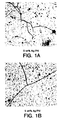
- Fig. 1 shows the crack density of the sintered ion transport material disc can be greatly reduced by increasing the amount of the second phase.
- the effect of the second phase concentration on the fracture strength of the ion transport material by 3-point bending tests is shown as curve 90 in Fig. 2.
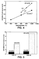
- Oxygen transport tests were performed on a 0.85 mm disc at temperature of 900-1000°C under an air/helium gradient with flow rates of 500 sccm (standard cubic centimeters per minute) for each stream at 1.2 atm pressure.
- the O 2 fluxes are 0.5, 0.7, 0.9 sccm/cm 2 at 900, 950, 997°C, respectively, curve 110, with the activation energy of 1.0 eV which is comparable to those obtained for single phase specimen, curve 112, as shown in Fig. 4. Therefore, the use of the second phase does not appear to diminish the oxygen transport performance of the material.
- Example II Mechanically Enhanced Ion Transport Membrane of La .2 Sr .8 Fe .69 Co .1 Cr .2 Mg .01 O x and 65Ag/35Pd alloy
- a dense dual phase disc of La .2 Sr .8 Fe .69 Co .1 Cr .2 Mg .01 O x with 20% 65Ag/35Pd (65 wt% Ag and 35 wt% Pd) was prepared according to the method of Example I except that 65Ag/35Pd is substituted for 50Ag/50Pd as a second phase.
- Room temperature N 2 permeation test confirmed that the disc is gas-tight.
- the disc also showed good mechanical strength after sintering at 1200°C in air with no microcracks being observed.
- Oxygen transport test was performed on a 0.9 mm disc at temperature of 1000°C under an air/helium gradient.
- the O 2 flux was 0.8 sccm/cm 2 at 1000°C which is comparable to that of dual phase specimen in Example I (with 20 wt% of 50Pd/50Ag second phase).
- the reactive purge test of this disc was also performed at 1000°C by using 10%H 2 -90%N 2 mixture on the purge side.
- An O 2 fluxes of 4.5 sccm/cm 2 was obtained at 1000°C which is also comparable to that of dual phase specimen with 20 wt% of 50Pd/50Ag alloy.
- Example III Mechanically Enhanced Ion Transport Membrane of La .2 Sr .8 Fe .69 Co .1 Cr .2 Mg .01 O x and 90Ag/10Pd alloy
- Dense dual phase discs of La .2 Sr .8 Fe .69 Co .1 Cr .2 Mg .01 O x with 20 wt% 90Ag/10Pd were prepared according to the method of Example 1 except that 90Ag/10Pd (supplied by Praxair Surface Technologies, Inc.) was substituted for 50Ag/50Pd as a second phase.
- the discs and bars were prepared by dry pressing under a pressure of 10.4 kpsi followed by binder burn-out (1°C/min from 25 to 400°C and hold for 1 hour), and sintered at 1200°C for 1 hour with a heating/cooling rate of 2°C/min in air.
- microcracking is often present in a ABO 3 perovskite structure, or a structure that can be derived from that (e.g. brownmillerite, A 2 B 2 O 5 ), as a result of a phase transition during the sintering and cooling.
- the microcracks are reduced in the La .2 Sr .8 Fe .69 Co .1 Cr .2 Mg .01 O x perovskite by adding the various amount of Ag/Pd second phase as shown in Example I and II.
- the invention disclosed herein is intended to cover suitable mixed conducting oxides presented by the structure A r A' s A'' t B u B' v B'' w O x where A,A',A'' are chosen from the Groups 1, 2, 3 and the F block lanthanides; and B,B',B' are chosen from the D block transition metals according to the Periodic Table of the Elements adopted by the IUPAC wherein 0 ⁇ r ⁇ 1, 0 ⁇ s ⁇ 1, 0 ⁇ t ⁇ 1, 0 ⁇ u ⁇ 1, 0 ⁇ v ⁇ 1, 0 ⁇ w ⁇ 1, and x is a number which renders the compound charge neutral.
- A,A' or A'' of the enumerated structure is a Group 2 metal selected from the group consisting of magnesium, calcium, strontium and barium.
- Preferred mixed conducting oxides are presented by the formula: A s A' t B u B' v B'' w O x wherein A represents a lanthanide, Y, or mixture thereof, A' represents an alkaline earth metal or mixture thereof; B represents Fe; B' represents Cr, Ti, or mixture thereof and B'' represents Mn, Co, V, Ni, Cu or mixture thereof and s, t, u, v and w each represents a number from 0 to about 1.
- Suitable first phase materials also include other ion-conducting ceramics in which microcracks may occur during sintering due to a high temperature polymorphic symmetry change, a compositional stress or a highly anisotropic thermal expansion coefficient.
- zirconia exhibits phase transformations at 1170°C (monoclinic to tetragonal) and 2370°C (tetragonal to cubic).
- the high temperature polymorphic symmetry changes usually result in cracks during sintering. Therefore, zirconia is usually stabilized in the fluorite-type cubic phase by introducing an appropriate di- or trivalent oxide to obtain the cubic symmetry.
- the invention herein is also intended to cover mechanical enhancement of other ceramics such as zirconia or ceria if they encounter a high temperature polymorphic symmetry change, a compositional stress or a highly anisotropic thermal expansion coefficient.
- an electronic/ionic conductor such as (B-MgLaCrO) 0.5 (YSZ) 0.5 , or a primarily ionic conductor such as zirconia or ceria combined with a perovskite, may be further combined with a constituent according to the present invention to form a membrane having at least three phases.
- Alternative embodiments of this invention are directed to coating a dense membrane by depositing the porous coating on at least one surface of the membrane.
- the coating modifies the surface of the membrane, thus believed to provide a catalytic effect during ion transport as well as providing structural stability on the surface layer.
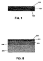
- FIG. 7 shows porous coating layers 702 and 703 deposited on both surfaces of dense solid electrolyte ion conducting membrane 701 .
- Fig. 8 shows another embodiment in which porous coating layers 802 and 803 are deposited on both surfaces of dense solid electrolyte ion conducting membrane 801 .
- Membrane 801 is supported on a porous support comprising intermediate support layer 804 and support layer 805 , with porous coating layer 803 between membrane 801 and intermediate support layer 804 .
- one preferred manufacturing process comprises dipping the dense membrane into a liquid precursor of the porous coating (e.g., slurry, colloidal solution), and subsequently drying and curing the resulting coating layer.
- a liquid precursor of the porous coating e.g., slurry, colloidal solution
- This method is a comparatively easier and more cost effective method for depositing a porous coating layer onto a dense surface over other methods available in the art.
- Suitable ion transport membrane materials include mixed conductors that can transport oxygen ions.
- the mixed conductor phase may transport both oxygen ions and electrons independent of the presence of the second electronic conducting phase.
- Examples of mixed conducting solid electrolytes of this invention are provided in Table I above, but this invention is not limited solely to these material compositions listed therein. Dense matrix materials other than those comprised only of mixed conductors are also contemplated by this invention.
- Suitable coating compositions may comprise of mixed conducting oxides that transport oxide ion as well as electron conductivity.
- Examples of the porous coating mixed conductor are given in Table I above, and may be the same or different from the mixed conducting oxides of the dense membrane.
- the coating may comprise a composition having a mixed conductor phase and a coating constituent.
- Suitable porous coating compositions include a combination of a mixed conductor and a coating constituent that can transport oxygen ions and/or electrons.
- the mixed conductors may transport both oxygen ions and conduct electrons independent of the presence of the coating constituent. It is preferred that the coating constituent constitute less than about thirty percent by volume of the total porous coating.
- the porous coating may be coated using various methods known to the skilled artisan.
- a preferred method is the slurry dip coating procedure. This method is preferred because of the ease and cost efficiency of coating the dense membrane.
- Other methods may include spin coating, chemical vapor deposition (CVD), electrochemical vapor deposition (EVD), physical vapor deposition (PVD) such as laser ablation and sputtering, thermal spray, plasma spray, RF plasma deposition and a combination thereof.
- the layer of porous coating should be thin relative to the surface of the dense membrane, such that the coating enhances the rate of surface reaction of the dense membrane. Accordingly, the porous coating layer has a thickness of less than about 50 microns, preferably less than 10 microns, and more preferably less than 5 microns.
- a porous support can also be used to enhance the structural stability of the membrane.
- the porous support may include inert, ionic conducting, mixed conducting and electronic conducting (metallic) material, or a combination thereof. Additionally, the porous support may contain catalytically enhancing constituents in combination with any of the inert, ionic conducting, mixed conducting and electronic conducting material, or a combination thereof.
- the porous support is particularly important where the dense matrix material is thin and fragile. Structurally, it is preferable to have at least one of the dense membrane and the porous coating being deposited on the porous support. An example of this embodiment is found in Fig. 8 as described above.
- a single-phase dense La .2 Sr .8 Fe .69 CO .1 Cr .2 Mg .01 O x (“LSFCCM”) powder (SSC) solid electrolyte ion conducting tube (7.1 mm ID, 9.7 mm OD, and approximately 15 cm long) was extruded, then sintered at 1250°C in nitrogen for 1 hour with a heating/cooling rate of 2°C/min.
- a purge gas containing 60% CH 4 , 10% CO 2 and 30% inert gas such as N 2 or Ar bubbled through water
- Example 5 presents an embodiment of the electrolyte membrane of the present invention.
- a single-phase dense LSFCCM solid electrolyte ion conducting tube similar to that of Example 4 was prepared.
- the tube was coated with a slurry dip coating procedure via Chemat Technology Model 201 to deploy a porous layer of approximately 1 ⁇ m size granules of a single-phase LSFCCM ion transport material on both surfaces of the tube.
- the coated material was then tested under the same manner as that described in Example 4. Enhancement of O 2 flux across the ion transport membrane with the aid of a porous coating is illustrated by the following table based on the experimental data.
- the coated ion transport tube showed a substantially higher O 2 flux (4 times) than the uncoated ion transport tube. In this case, data points with similar feed flow rates are shown.
- the coated single-phase tube was observed to remove more oxygen from similar feed-streams.
- Example 6 A dual-phase ion transport tube of LSFCCM with 20
- wt% 50Ag/50Pd 50 wt.% Ag and 50 wt.% Pd
- Dual phase LSFCCM ion transport membrane slip was prepared by mixing 20 wt% of the 50Ag/50Pd alloy (DeGussa) and La .2 Sr .8 Fe .69 CO .1 Cr .2 Mg .01 O x powder (SSC) and 2 drops Darvan C dispersant with water to a 35% solids concentration.
- the slip was milled for 5 hours, slipcast in a gypsum mold, then sintered at 1250°C in air for 1 hour with a heating/cooling rate of 2°C/min.
- the dual-phase tubes was tested in the same manner as that described in Example 4.
- Example 7 presents another embodiment of the present invention.
- a dual-phase LSFCCM ion transport tube similar to that of Example 6 was prepared.
- the tube was coated using a slurry dip coating procedure via Chemat Technology Model 201 was used to deploy a porous layer of approximately 1 ⁇ m size granules of a single-phase LSFCCM ion transport material on both surfaces of one of the tubes, whereas the the tube from Eample 6 was left uncoated.
- Substantial O 2 -flux enhancement (3.8 times) was observed with the porous single-phase ion transport layer deployed on the tubes.
- data points with similar product O 2 concentrations were chosen.
- a much higher feed flow could be used in the coated dual-phase tube to remove O 2 to a comparable extent.
- Example 8 presents yet another embodiment of the present invention.
- An extruded dual-phase LSFCCM ion transport tube similar to that of Example 4 was prepared.
- the tube was coated using a slurry dip coating procedure via Chemat Technology Model 201 was used to deploy a porous layer of approximately 1 ⁇ m size granules of a dual phase LSFCCM ion transport material comprising LSFCCM and a constituent on both surfaces of one of the tubes.
- the constituent is made from 50Ag/50Pd and is about 20 wt.% (approximately 11 vol.%) of the entire porous layer.
- Substantial O 2 -flux enhancement (3.7 times) was observed with the porous single-phase ion transport layer deployed on the tubes.
- Dual-phase ion transport tube with a 20 m porous coating of 1 m single-phase ion transport granules (Example 7): 17.8 20.9 % 5.34 % 790 660 1062 7.3 C.
- Dual-phase ion transport tube with a 20 m porous coating of 1 m dual-phase ion transport granules (Example 8): 37.7 20.9 % 12.92 % 2884 2620 1017 7.0 Note that in each example the ion transport tube with the mixed conductor and electronic conductor porous layer, the oxygen flux increased nearly four times that of the dense uncoated ion transport tube.
- a dual phase disc was prepared. Both surfaces of sintered discs were then polished to obtain a thickness of 0.9 mm.
- the oxygen permeation rate was measured on the disc at 900°C under an air/helium gradient.
- the disc specimen was sealed in an alumina test cell with Ag paste.
- a HP 5890 Gas Chromatograph and oxygen analyzer were used to analyze the gas compositions and calculate the oxygen fluxes. The flux results (in sccm/cm 2 ) at 900°C are summarized in Table IV.
- Example 10 presents another embodiment of the electrolyte membrane of the present invention.
- a dual phase disc similar to that of Example 9 was prepared and was polished to obtain a thickness of 0.6 mm.
- LSFCCM ion transport material similar to that from Example 5 were deposited onto the surface of the disc which was fixed on a spinning coater. A spinning speed of 3500 rpm for 20 seconds was used for the deposition of modification layer. After spin-coating, the as-deposited coating of LSFCCM ion transport material on the disc was dried on a hot plate at 80°C for 5 minutes, then transferred to a ceramic-top hot plate and heated at approximately 300°C for at least 5 minutes. The entire coating and drying process was repeated until a 1 ⁇ m LSFCCM film formed on the membrane surface. The dual phase disc was then tested in the same manner as described in Example 9.
- suitable first phase materials may conduct proton ions instead of or together with oxygen ions for applications involving hydrogen.
Landscapes
- Chemical & Material Sciences (AREA)
- Chemical Kinetics & Catalysis (AREA)
- Engineering & Computer Science (AREA)
- Inorganic Chemistry (AREA)
- Organic Chemistry (AREA)
- Materials Engineering (AREA)
- Water Supply & Treatment (AREA)
- Dispersion Chemistry (AREA)
- Urology & Nephrology (AREA)
- Health & Medical Sciences (AREA)
- Manufacturing & Machinery (AREA)
- Analytical Chemistry (AREA)
- Separation Using Semi-Permeable Membranes (AREA)
- Fuel Cell (AREA)
- Conductive Materials (AREA)
- Catalysts (AREA)
- Compositions Of Oxide Ceramics (AREA)
Applications Claiming Priority (4)
| Application Number | Priority Date | Filing Date | Title |
|---|---|---|---|
| US08/775,683 US5911860A (en) | 1996-12-31 | 1996-12-31 | Solid electrolyte membrane with mechanically-enhancing constituents |
| US775683 | 1996-12-31 | ||
| US08/850,672 US5938822A (en) | 1997-05-02 | 1997-05-02 | Solid electrolyte membrane with porous catalytically-enhancing constituents |
| US850672 | 1997-05-02 |
Publications (3)
| Publication Number | Publication Date |
|---|---|
| EP0850679A2 true EP0850679A2 (fr) | 1998-07-01 |
| EP0850679A3 EP0850679A3 (fr) | 1998-08-05 |
| EP0850679B1 EP0850679B1 (fr) | 2005-03-30 |
Family
ID=27119081
Family Applications (1)
| Application Number | Title | Priority Date | Filing Date |
|---|---|---|---|
| EP97122945A Revoked EP0850679B1 (fr) | 1996-12-31 | 1997-12-29 | Membrane électrolytique solide comprenant un constituant pour l'amélioration des propriétés mécaniques |
Country Status (10)
| Country | Link |
|---|---|
| EP (1) | EP0850679B1 (fr) |
| JP (1) | JP3699264B2 (fr) |
| KR (1) | KR100354727B1 (fr) |
| CN (1) | CN1235304C (fr) |
| BR (1) | BR9706487A (fr) |
| CA (1) | CA2225871C (fr) |
| DE (1) | DE69732894T2 (fr) |
| ES (1) | ES2236779T3 (fr) |
| ID (1) | ID19327A (fr) |
| NO (1) | NO318928B1 (fr) |
Cited By (7)
| Publication number | Priority date | Publication date | Assignee | Title |
|---|---|---|---|---|
| EP0982068A2 (fr) * | 1998-08-26 | 2000-03-01 | Praxair Technology, Inc. | Procédé pour preparation d'une membrane céramique |
| EP1026123A2 (fr) * | 1999-02-02 | 2000-08-09 | Praxair Technology, Inc. | Membrane solide multiphase conductrice d'ions et d'électrons, à faible pourcentage volumétrique de phase conductrice d'électrons, et procédés pour sa préparation |
| EP1027916A1 (fr) * | 1999-02-02 | 2000-08-16 | Praxair Technology, Inc. | Perovskite mixte conductrice pour une membrane céramique de transport d'ions |
| WO2001089010A1 (fr) | 2000-05-18 | 2001-11-22 | Corning Incorporated | Piles a combustible oxyde solide possedant des electrodes composites symetriques |
| KR100315894B1 (ko) * | 1999-12-30 | 2001-12-24 | 박호군 | 고분자 전해질을 이용한 알켄 분리용 고체상 촉진 수송분리막 |
| KR100315896B1 (ko) * | 1999-12-30 | 2001-12-24 | 박호군 | 고체 고분자 전해질을 이용한 촉진 수송 분리막 |
| EP1531149A2 (fr) * | 2003-11-17 | 2005-05-18 | Air Products And Chemicals, Inc. | Chauffage contrôlé et refroidissement contrôlé de matériaux d'oxyde de métal de conducteur mixte |
Families Citing this family (6)
| Publication number | Priority date | Publication date | Assignee | Title |
|---|---|---|---|---|
| US7229712B2 (en) * | 2003-03-07 | 2007-06-12 | Microcell Corporation | Fuel cell structures and assemblies |
| US7229537B2 (en) * | 2003-07-10 | 2007-06-12 | Praxair Technology, Inc. | Composite oxygen ion transport element |
| KR100612570B1 (ko) * | 2004-04-21 | 2006-08-11 | 주식회사 엘지화학 | 신규 결정 구조를 갖는 금속 복합 산화물 및 이들의 이온전도체로서의 용도 |
| JP4652001B2 (ja) * | 2004-09-17 | 2011-03-16 | 株式会社ノリタケカンパニーリミテド | 酸化物イオン伝導体および酸素分離膜エレメント |
| CN100361730C (zh) * | 2005-01-14 | 2008-01-16 | 山东理工大学 | 用于空分制氧的陶瓷中空纤维膜反应器及其制法和应用 |
| KR101335464B1 (ko) * | 2012-06-29 | 2013-11-29 | 한국과학기술연구원 | 산화 비스무스를 포함하는 세리아계 조성물, 세리아계 복합 전해질 분말 및 이를 이용한 소결 방법 및 소결체 |
Citations (4)
| Publication number | Priority date | Publication date | Assignee | Title |
|---|---|---|---|---|
| WO1992000934A2 (fr) * | 1990-07-06 | 1992-01-23 | Igr Enterprises, Inc. | Composites ceramiques ductiles |
| EP0663232A2 (fr) * | 1994-01-12 | 1995-07-19 | Air Products And Chemicals, Inc. | Membranes de transport d'ions avec couche dense contenant un catalyseur |
| US5616223A (en) * | 1992-05-11 | 1997-04-01 | Gas Research Institute | Mixed ionic-electronic conducting composites for oxygen separation and electrocatalysis |
| US5624542A (en) * | 1992-05-11 | 1997-04-29 | Gas Research Institute | Enhancement of mechanical properties of ceramic membranes and solid electrolytes |
Family Cites Families (5)
| Publication number | Priority date | Publication date | Assignee | Title |
|---|---|---|---|---|
| NO304808B1 (no) * | 1989-05-25 | 1999-02-15 | Standard Oil Co Ohio | Fast multikomponent membran, fremgangsmaate for fresmtilling av en slik membran samt anvendelse av denne |
| JPH06103988A (ja) * | 1992-09-17 | 1994-04-15 | Ngk Insulators Ltd | 固体電解質型燃料電池 |
| JPH0769720A (ja) * | 1993-06-17 | 1995-03-14 | Toho Gas Co Ltd | 複合材分散強化型固体電解質材料 |
| JP3331056B2 (ja) * | 1994-07-14 | 2002-10-07 | 東邦瓦斯株式会社 | 分散強化型固体電解質材料及びこれを用いた固体電解質焼結体 |
| JPH0987022A (ja) * | 1995-09-28 | 1997-03-31 | Shin Etsu Chem Co Ltd | 繊維強化導電性セラミックス |
-
1997
- 1997-12-18 ID IDP973922A patent/ID19327A/id unknown
- 1997-12-26 JP JP36698597A patent/JP3699264B2/ja not_active Expired - Fee Related
- 1997-12-29 DE DE69732894T patent/DE69732894T2/de not_active Expired - Fee Related
- 1997-12-29 KR KR1019970076162A patent/KR100354727B1/ko not_active IP Right Cessation
- 1997-12-29 ES ES97122945T patent/ES2236779T3/es not_active Expired - Lifetime
- 1997-12-29 BR BR9706487A patent/BR9706487A/pt not_active IP Right Cessation
- 1997-12-29 CN CNB971297355A patent/CN1235304C/zh not_active Expired - Fee Related
- 1997-12-29 NO NO19976092A patent/NO318928B1/no unknown
- 1997-12-29 EP EP97122945A patent/EP0850679B1/fr not_active Revoked
- 1997-12-29 CA CA002225871A patent/CA2225871C/fr not_active Expired - Fee Related
Patent Citations (4)
| Publication number | Priority date | Publication date | Assignee | Title |
|---|---|---|---|---|
| WO1992000934A2 (fr) * | 1990-07-06 | 1992-01-23 | Igr Enterprises, Inc. | Composites ceramiques ductiles |
| US5616223A (en) * | 1992-05-11 | 1997-04-01 | Gas Research Institute | Mixed ionic-electronic conducting composites for oxygen separation and electrocatalysis |
| US5624542A (en) * | 1992-05-11 | 1997-04-29 | Gas Research Institute | Enhancement of mechanical properties of ceramic membranes and solid electrolytes |
| EP0663232A2 (fr) * | 1994-01-12 | 1995-07-19 | Air Products And Chemicals, Inc. | Membranes de transport d'ions avec couche dense contenant un catalyseur |
Non-Patent Citations (3)
| Title |
|---|
| BAMBA N ET AL: "Fabrication and mechanical properties of nanosized SiC particulate reinforced yttria stabilized zirconia composites" NANOSTRUCTURED MATERIALS, vol. 1-8, no. 9, 1997, page 497-500 XP004065183 * |
| OE K -I ET AL: "Toughening of ionic conductive zirconia ceramics utilizing a non -linear effect" SOLID STATE IONICS, vol. 1-2, no. 91, 1 October 1996, page 131-136 XP004071614 * |
| VAN DE GOOR G ET AL: "Electrically conductive ceramic composites" SOLID STATE IONICS, vol. 2002, no. 101-103, November 1997, page 1163-1170 XP004103752 * |
Cited By (13)
| Publication number | Priority date | Publication date | Assignee | Title |
|---|---|---|---|---|
| EP0982068A2 (fr) * | 1998-08-26 | 2000-03-01 | Praxair Technology, Inc. | Procédé pour preparation d'une membrane céramique |
| JP2000128545A (ja) * | 1998-08-26 | 2000-05-09 | Praxair Technol Inc | セラミック膜を作製する方法 |
| EP0982068A3 (fr) * | 1998-08-26 | 2000-11-02 | Praxair Technology, Inc. | Procédé pour preparation d'une membrane céramique |
| EP1026123A2 (fr) * | 1999-02-02 | 2000-08-09 | Praxair Technology, Inc. | Membrane solide multiphase conductrice d'ions et d'électrons, à faible pourcentage volumétrique de phase conductrice d'électrons, et procédés pour sa préparation |
| EP1027916A1 (fr) * | 1999-02-02 | 2000-08-16 | Praxair Technology, Inc. | Perovskite mixte conductrice pour une membrane céramique de transport d'ions |
| EP1026123A3 (fr) * | 1999-02-02 | 2003-01-29 | Praxair Technology, Inc. | Membrane solide multiphase conductrice d'ions et d'électrons, à faible pourcentage volumétrique de phase conductrice d'électrons, et procédés pour sa préparation |
| KR100315894B1 (ko) * | 1999-12-30 | 2001-12-24 | 박호군 | 고분자 전해질을 이용한 알켄 분리용 고체상 촉진 수송분리막 |
| KR100315896B1 (ko) * | 1999-12-30 | 2001-12-24 | 박호군 | 고체 고분자 전해질을 이용한 촉진 수송 분리막 |
| WO2001089010A1 (fr) | 2000-05-18 | 2001-11-22 | Corning Incorporated | Piles a combustible oxyde solide possedant des electrodes composites symetriques |
| EP1293004A1 (fr) * | 2000-05-18 | 2003-03-19 | Corning Incorporated | Piles a combustible oxyde solide possedant des electrodes composites symetriques |
| EP1293004A4 (fr) * | 2000-05-18 | 2007-09-12 | Corning Inc | Piles a combustible oxyde solide possedant des electrodes composites symetriques |
| EP1531149A2 (fr) * | 2003-11-17 | 2005-05-18 | Air Products And Chemicals, Inc. | Chauffage contrôlé et refroidissement contrôlé de matériaux d'oxyde de métal de conducteur mixte |
| EP1531149A3 (fr) * | 2003-11-17 | 2011-07-13 | Air Products And Chemicals, Inc. | Chauffage contrôlé et refroidissement contrôlé de matériaux d'oxyde de métal de conducteur mixte |
Also Published As
| Publication number | Publication date |
|---|---|
| JPH10214519A (ja) | 1998-08-11 |
| KR19980064774A (ko) | 1998-10-07 |
| NO318928B1 (no) | 2005-05-23 |
| ID19327A (id) | 1998-07-02 |
| EP0850679A3 (fr) | 1998-08-05 |
| KR100354727B1 (ko) | 2003-01-24 |
| NO976092L (no) | 1998-07-01 |
| CA2225871C (fr) | 2002-03-26 |
| DE69732894D1 (de) | 2005-05-04 |
| ES2236779T3 (es) | 2005-07-16 |
| CA2225871A1 (fr) | 1998-06-30 |
| MX9710396A (es) | 1998-08-30 |
| EP0850679B1 (fr) | 2005-03-30 |
| CN1195205A (zh) | 1998-10-07 |
| JP3699264B2 (ja) | 2005-09-28 |
| NO976092D0 (no) | 1997-12-29 |
| DE69732894T2 (de) | 2006-04-06 |
| CN1235304C (zh) | 2006-01-04 |
| BR9706487A (pt) | 1999-08-10 |
Similar Documents
| Publication | Publication Date | Title |
|---|---|---|
| US5938822A (en) | Solid electrolyte membrane with porous catalytically-enhancing constituents | |
| US5911860A (en) | Solid electrolyte membrane with mechanically-enhancing constituents | |
| US6187157B1 (en) | Multi-phase solid electrolyte ionic transport membrane and method for fabricating same | |
| US20100015014A1 (en) | Mixed Ionic and Electronic Conducting Membrane | |
| US6235417B1 (en) | Two-phase hydrogen permeation membrane | |
| US5342703A (en) | Solid electrolyte type fuel cell and method for producing the same | |
| US6332964B1 (en) | Multi-phase solid ion and electron conducting membrane with low volume percentage electron conducting phase and methods for fabricating | |
| EP0982068A2 (fr) | Procédé pour preparation d'une membrane céramique | |
| EP0850679B1 (fr) | Membrane électrolytique solide comprenant un constituant pour l'amélioration des propriétés mécaniques | |
| US8012380B2 (en) | Proton conducting ceramic membranes for hydrogen separation | |
| JP2014510014A (ja) | 低pO2雰囲気中で得られるセラミックデバイスのための焼結添加剤 | |
| US6146445A (en) | Stabilized perovskite for ceramic membranes | |
| US20100092829A1 (en) | Gas electrode, method for making the same and uses thereof | |
| EP0994083B1 (fr) | Matériau céramique stratifié | |
| JP2005503246A (ja) | 酸化物イオン導電性セラミック膜構造/微細構造、空気から酸素を分離するための使用 | |
| JP2007134133A (ja) | 固体電解質型燃料電池 | |
| Jue et al. | Electrochemical Vapor Deposition of CeO2: Kinetics of Deposition of a Composite, Two‐Layer Electrolyte | |
| Jeon et al. | Oxygen permeation through dense La0. 1Sr0. 9Co0. 8Fe0. 2O3− δ perovskite membranes: Catalytic effect of porous La0. 1Sr0. 9Co0. 8Fe0. 2O3− δ layers | |
| MXPA97010396A (en) | Solid electrolyte membrane with mechanically improving components and catalytically poro improvers | |
| Brinkman et al. | Kinetics of the EVD process for growing thin zirconia/yttria films on porous alumina substrates | |
| KR20000062853A (ko) | 낮은 부피 비의 전자 전도상을 갖는 다상 고체 이온 및 전자 전도막과 그 제조 방법 | |
| AU1484000A (en) | Multi-phase solid ion and electron conducting membrane with low volume percentage electron conducting pahse and methods for fabricating same | |
| Haldane | Ceramic fuel cell anode enhancement by polarized electrochemical vapour deposition |
Legal Events
| Date | Code | Title | Description |
|---|---|---|---|
| PUAI | Public reference made under article 153(3) epc to a published international application that has entered the european phase |
Free format text: ORIGINAL CODE: 0009012 |
|
| PUAL | Search report despatched |
Free format text: ORIGINAL CODE: 0009013 |
|
| AK | Designated contracting states |
Kind code of ref document: A2 Designated state(s): BE DE ES FR GB IT NL |
|
| AX | Request for extension of the european patent |
Free format text: AL;LT;LV;MK;RO;SI |
|
| AK | Designated contracting states |
Kind code of ref document: A3 Designated state(s): AT BE CH DE DK ES FI FR GB GR IE IT LI LU MC NL PT SE |
|
| AX | Request for extension of the european patent |
Free format text: AL;LT;LV;MK;RO;SI |
|
| 17P | Request for examination filed |
Effective date: 19980812 |
|
| AKX | Designation fees paid |
Free format text: BE DE ES FR GB IT NL |
|
| RBV | Designated contracting states (corrected) |
Designated state(s): BE DE ES FR GB IT NL |
|
| 17Q | First examination report despatched |
Effective date: 20020327 |
|
| GRAP | Despatch of communication of intention to grant a patent |
Free format text: ORIGINAL CODE: EPIDOSNIGR1 |
|
| RTI1 | Title (correction) |
Free format text: SOLID ELECTROLYTE MEMBRANE WITH MECHANICALLY-ENHANCING CONSTITUENT |
|
| GRAS | Grant fee paid |
Free format text: ORIGINAL CODE: EPIDOSNIGR3 |
|
| GRAA | (expected) grant |
Free format text: ORIGINAL CODE: 0009210 |
|
| 18D | Application deemed to be withdrawn |
Effective date: 20040811 |
|
| D18D | Application deemed to be withdrawn (deleted) | ||
| AK | Designated contracting states |
Kind code of ref document: B1 Designated state(s): BE DE ES FR GB IT NL |
|
| REF | Corresponds to: |
Ref document number: 69732894 Country of ref document: DE Date of ref document: 20050504 Kind code of ref document: P |
|
| REG | Reference to a national code |
Ref country code: ES Ref legal event code: FG2A Ref document number: 2236779 Country of ref document: ES Kind code of ref document: T3 |
|
| PGFP | Annual fee paid to national office [announced via postgrant information from national office to epo] |
Ref country code: NL Payment date: 20051129 Year of fee payment: 9 |
|
| PGFP | Annual fee paid to national office [announced via postgrant information from national office to epo] |
Ref country code: FR Payment date: 20051216 Year of fee payment: 9 |
|
| PGFP | Annual fee paid to national office [announced via postgrant information from national office to epo] |
Ref country code: GB Payment date: 20051221 Year of fee payment: 9 |
|
| PGFP | Annual fee paid to national office [announced via postgrant information from national office to epo] |
Ref country code: ES Payment date: 20051226 Year of fee payment: 9 |
|
| PLBI | Opposition filed |
Free format text: ORIGINAL CODE: 0009260 |
|
| PGFP | Annual fee paid to national office [announced via postgrant information from national office to epo] |
Ref country code: DE Payment date: 20060131 Year of fee payment: 9 |
|
| PLAX | Notice of opposition and request to file observation + time limit sent |
Free format text: ORIGINAL CODE: EPIDOSNOBS2 |
|
| PGFP | Annual fee paid to national office [announced via postgrant information from national office to epo] |
Ref country code: BE Payment date: 20060202 Year of fee payment: 9 |
|
| 26 | Opposition filed |
Opponent name: AIR PRODUCTS AND CHEMICALS, INC. Effective date: 20051221 |
|
| ET | Fr: translation filed | ||
| NLR1 | Nl: opposition has been filed with the epo |
Opponent name: AIR PRODUCTS AND CHEMICALS, INC. |
|
| PLAF | Information modified related to communication of a notice of opposition and request to file observations + time limit |
Free format text: ORIGINAL CODE: EPIDOSCOBS2 |
|
| PLBB | Reply of patent proprietor to notice(s) of opposition received |
Free format text: ORIGINAL CODE: EPIDOSNOBS3 |
|
| PG25 | Lapsed in a contracting state [announced via postgrant information from national office to epo] |
Ref country code: BE Free format text: LAPSE BECAUSE OF NON-PAYMENT OF DUE FEES Effective date: 20061231 |
|
| PG25 | Lapsed in a contracting state [announced via postgrant information from national office to epo] |
Ref country code: NL Free format text: LAPSE BECAUSE OF NON-PAYMENT OF DUE FEES Effective date: 20070701 |
|
| PG25 | Lapsed in a contracting state [announced via postgrant information from national office to epo] |
Ref country code: DE Free format text: LAPSE BECAUSE OF NON-PAYMENT OF DUE FEES Effective date: 20070703 |
|
| GBPC | Gb: european patent ceased through non-payment of renewal fee |
Effective date: 20061229 |
|
| NLV4 | Nl: lapsed or anulled due to non-payment of the annual fee |
Effective date: 20070701 |
|
| REG | Reference to a national code |
Ref country code: FR Ref legal event code: ST Effective date: 20070831 |
|
| PG25 | Lapsed in a contracting state [announced via postgrant information from national office to epo] |
Ref country code: GB Free format text: LAPSE BECAUSE OF NON-PAYMENT OF DUE FEES Effective date: 20061229 |
|
| BERE | Be: lapsed |
Owner name: *PRAXAIR TECHNOLOGY INC. Effective date: 20061231 |
|
| REG | Reference to a national code |
Ref country code: ES Ref legal event code: FD2A Effective date: 20061230 |
|
| PG25 | Lapsed in a contracting state [announced via postgrant information from national office to epo] |
Ref country code: FR Free format text: LAPSE BECAUSE OF NON-PAYMENT OF DUE FEES Effective date: 20070102 Ref country code: ES Free format text: LAPSE BECAUSE OF NON-PAYMENT OF DUE FEES Effective date: 20061230 |
|
| PGFP | Annual fee paid to national office [announced via postgrant information from national office to epo] |
Ref country code: IT Payment date: 20071228 Year of fee payment: 11 |
|
| RDAF | Communication despatched that patent is revoked |
Free format text: ORIGINAL CODE: EPIDOSNREV1 |
|
| RDAF | Communication despatched that patent is revoked |
Free format text: ORIGINAL CODE: EPIDOSNREV1 |
|
| RDAG | Patent revoked |
Free format text: ORIGINAL CODE: 0009271 |
|
| STAA | Information on the status of an ep patent application or granted ep patent |
Free format text: STATUS: PATENT REVOKED |
|
| 27W | Patent revoked |
Effective date: 20081113 |