EP0849865B1 - Manufacturing method of a permanent magnets commutator motor with a lower pole number and high resolution rotation sensor - Google Patents
Manufacturing method of a permanent magnets commutator motor with a lower pole number and high resolution rotation sensor Download PDFInfo
- Publication number
- EP0849865B1 EP0849865B1 EP97121588A EP97121588A EP0849865B1 EP 0849865 B1 EP0849865 B1 EP 0849865B1 EP 97121588 A EP97121588 A EP 97121588A EP 97121588 A EP97121588 A EP 97121588A EP 0849865 B1 EP0849865 B1 EP 0849865B1
- Authority
- EP
- European Patent Office
- Prior art keywords
- magnetized
- poles
- motor housing
- rotor
- commutator
- Prior art date
- Legal status (The legal status is an assumption and is not a legal conclusion. Google has not performed a legal analysis and makes no representation as to the accuracy of the status listed.)
- Expired - Lifetime
Links
Images

Classifications
-
- H—ELECTRICITY
- H02—GENERATION; CONVERSION OR DISTRIBUTION OF ELECTRIC POWER
- H02K—DYNAMO-ELECTRIC MACHINES
- H02K15/00—Methods or apparatus specially adapted for manufacturing, assembling, maintaining or repairing of dynamo-electric machines
- H02K15/02—Methods or apparatus specially adapted for manufacturing, assembling, maintaining or repairing of dynamo-electric machines of stator or rotor bodies
- H02K15/03—Methods or apparatus specially adapted for manufacturing, assembling, maintaining or repairing of dynamo-electric machines of stator or rotor bodies having permanent magnets
-
- H—ELECTRICITY
- H02—GENERATION; CONVERSION OR DISTRIBUTION OF ELECTRIC POWER
- H02K—DYNAMO-ELECTRIC MACHINES
- H02K15/00—Methods or apparatus specially adapted for manufacturing, assembling, maintaining or repairing of dynamo-electric machines
Definitions
- the invention relates to a method of manufacture a permanently excited low-pole commutator motor with a multi-pole pole wheel as a rotary pulse encoder according to claim 1; electric motors manufactured in this way are in particular for use as servomotors in electric clutch actuators or automatic brake actuators in Motor vehicles provided.
- Motors of the aforementioned type must have a particular size axial, compact and closed with moisture-proof Design with simple manufacturing and assembly technology his.
- an actuator with such an electric motor depending on the smallest changes in movement to be able to control, also turns detection with high Resolution required with only a small metrological Circuit complexity advantageous due to a multipolar magnetized Magnet wheel as angular momentum encoder is achievable, however technologically a relatively large diameter of the magnet wheel to apply the large number of necessary magnetic poles of the circumferential area.
- JP 52 44 754 is a method for external magnetization a fully assembled commutator motor with held within the motor housing on the inner circumference of the housing, to magnetize stator magnets and axially in front of the commutator motor known on the rotor shaft arranged rotor.
- DE 40 01 273 C2 describes the static structure of a Commutator motor with a commutator on its one axial End and a magnet wheel of a frequency generator in comparison to the larger diameter commutator at its other axial end.
- the multi-pole magnetic pole wheel in a simple way between the bearings of the rotor of the electric motor and use it to protect against moisture inside the motor housing, without the magnetization of the Permanent excitation of the electric motor provided on the inner circumference of the housing arranged magnetizable shell parts with the rotor plugged into the motor housing by an outside magnetization device attached to the motor is dispensed with must be the one for the magnetization of the shell parts strong magnetic field with one for the number of poles for the angular momentum encoder provided pole wheel different number of poles generated.
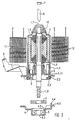
- FIG. 3 shows an exploded view using a commutator servomotor for an electric clutch actuator in a motor vehicle a pre-assembly position with a upper first component unit, a lower second component unit and an intermediate component in the form of the multi-pole magnetized magnet wheel; all component units or Components are to be assembled to form a servomotor according to FIG. 1.
- the first upper component unit contains essential individual components a cup-shaped motor housing 1.1 with stator side fixed, by a magnetizing device 11; 12 with for the generation of a two-pole magnetic field opposite on the circumference of the motor housing 1.1 Magnetizing coils 11 and 12 to be magnetized shell parts 1.2; 1.2 and a plugged into the motor housing 1.1, as a magnetic yoke for magnetization the magnetizing device 11; 12 also used rotor 1.3-1.6 with one at its upper shaft end in a spherical floating bearing 10 rotatably mounted rotor shaft in the motor housing 1.1 1.3 with the rotor laminated core 1.4 held thereon, in one introduced a commutator 1.6 connected rotor winding 1.5 is, as well as with an axially from the open end of the motor housing 1.1 retractable brush holder 2 with brushes 2.1.
- the rotor winding 1.5 is on the commutator 1.6 grinding brushes guided in the brush holder 2 2.1 fed by an external feed or control line, the can be fed via an external connector 9.
- One of those Angular momentum encoder in the form of the magnetized magnet wheel 3 assigned angular momentum receiver 6 in the form of a Circuit arrangement with two here - in particular from FIG. 2 obvious - Hall IC's is advantageously without separate Self-holder on the brush holder 2 close to brought the pole wheel 3.
- the second lower Component unit consisting of a bearing plate 4 and a second bearing 5 pre-assembled therein, in particular a fixed ball bearing, out against the motor housing 1.1 and on this attached; can press on the bearing 5 on the free one shaft end of the rotor shaft 1.3 in turn the support tool 8 advantageously used for a corresponding back pressure become.
- a lead out through a central opening 4.3 of the bearing plate 4 and compared to the surrounding end shield 4 and / or in the implementation through the brush holder 2 opposite this sealable output shaft end 1.31 of the rotor shaft 1.3 is in present application with an output toothing, in particular a toothing axially loading the rotor shaft 1.3, to drive an electrical clutch actuator provided in a motor vehicle.
- the one such an output caused axial pressure on the rotor shaft will certainly be advantageous in terms of manufacturing technology caught on the motor side in that the rotor shaft bearing 5 in one axial direction against the bottom of the pot 4.1 a cup-shaped depression formed in the bearing plate 4 rests and in the other axial direction in the sense a fixed bearing through from the pot rim 4.2 over the outer circumference the caulking of the fixed bearing part 4.21 is firmly positionable.
Description
Die Erfindung bezieht sich auf ein Verfahren zur Herstellung eines permanenterregten niederpoligen Kommutatormotors mit einem hochpoligen Polrad als Drehimpuls-Geber gemäß Patentanspruch 1; derartig hergestellte Elektromotore sind insbesondere zum Einsatz als Stellmotore in elektrischen Kupplungs-Stellantrieben bzw. automatischen Brems-Stellantrieben in Kraftfahrzeugen vorgesehen.The invention relates to a method of manufacture a permanently excited low-pole commutator motor with a multi-pole pole wheel as a rotary pulse encoder according to claim 1; electric motors manufactured in this way are in particular for use as servomotors in electric clutch actuators or automatic brake actuators in Motor vehicles provided.
Motore der vorgenannten Art müssen in ihrer Baugröße, insbesondere axial, kompakt und bei feuchtigkeitsdicht geschlossenen Bauart fertigungs- bzw. montagetechnisch einfach aufgebaut sein. Um einen Stellantrieb mit einem derartigen Elektromotor in Abhängigkeit von kleinsten Bewegungsänderungen ansteuern zu können, wird außerdem eine Dreherkennung mit hoher Auflösung gefordert, die bei nur geringem meßtechnischen Schaltungsaufwand vorteilhaft durch ein vielpolig magnetisiertes Polrad als Drehimpuls-Geber erreichbar ist, jedoch technologisch einen relativ großen Durchmesser des Polrades zur Aufbringung der Vielzahl von notwendigen Magnetpolen auf der Umfangssfläche voraussetzt. Üblicherweise werden bei derartigen Forderungen bzw. Voraussetzungen separate Dreherkennungssysteme verwendet, die außerhalb des eigentlichen Motorgehäuses des Elektromotors nach dessen Zusammenbau montiert werden und die durch jeweils einen gesonderten Tragkörper, einen Hall-IC-Drehimpulsempfänger mit gesonderten Anschlußleitungen und ein Polrad axial außerhalb der Lagerstellen des Stellmotors gekennzeichnet sind. Motors of the aforementioned type must have a particular size axial, compact and closed with moisture-proof Design with simple manufacturing and assembly technology his. To an actuator with such an electric motor depending on the smallest changes in movement to be able to control, also turns detection with high Resolution required with only a small metrological Circuit complexity advantageous due to a multipolar magnetized Magnet wheel as angular momentum encoder is achievable, however technologically a relatively large diameter of the magnet wheel to apply the large number of necessary magnetic poles of the circumferential area. Usually such Requirements and requirements separate turn detection systems used that outside of the actual engine case of the electric motor after it has been assembled and each by a separate support body, a Hall IC rotary pulse receiver with separate connection lines and a magnet wheel axially outside of the bearings of the Actuator are marked.
Durch die JP 52 44 754 ist ein Verfahren zur externen Magnetisierung eines komplett montierten Kommutatormotors mit innerhalb des Motorgehäuses am Gehäuseinnenumfang gehaltenen, zu magnetisierenden Stator-Magneten und axial vor dem Kommutatormotor auf der Rotorwelle angeordnetem Polrad bekannt.JP 52 44 754 is a method for external magnetization a fully assembled commutator motor with held within the motor housing on the inner circumference of the housing, to magnetize stator magnets and axially in front of the commutator motor known on the rotor shaft arranged rotor.
Die DE 40 01 273 C2 beschreibt den statischen Aufbau eines Kommutatormotors mit einem Kommutator an seinem einen axialen Ende und einem Polrad eines Frequenzgenerators mit im Vergleich zu dem Kommutator größeren Durchmesser an seinem anderen axialen Ende.DE 40 01 273 C2 describes the static structure of a Commutator motor with a commutator on its one axial End and a magnet wheel of a frequency generator in comparison to the larger diameter commutator at its other axial end.
Gemäß Aufgabe der vorliegenden Erfindung soll ein dem gegenüber mit fertigungs- bzw. montagetechnisch geringerem Aufwand herstellbarer Stellmotor mit hochauflösender Dreherkennung geschaffen werden.According to the object of the present invention, one should with less manufacturing or assembly technology producible servomotor with high-resolution rotation detection be created.
Die Lösung der vorgenannten Aufgabe gelingt erfindungsgemäß durch ein Verfahren zur Herstellung eines permanenterregten niederpoligen Elektromotors mit einem hochpoligen Polrad gemäß Patentanspruch 1; vorteilhafte Ausgestaltungen des erfindungsgemäßen Verfahrens sind jeweils Gegenstand der Unteransprüche.The above object is achieved according to the invention through a process to produce a permanently excited low-pole electric motor with a high-pole pole wheel according Claim 1; advantageous embodiments of the invention Procedures are the subject of the subclaims.
Bei dem erfindungsgemäßen Verfahren läßt sich in kompakter Bauform das hochpolig magnetische Polrad auf einfache Weise zwischen den Lagerstellen des Rotors des Elektromotors und damit feuchtigkeitsgeschützt innerhalb des Motorgehäuses anbringen, ohne daß deswegen auf die Magnetisierung der für die Permanenterregung des Elektromotors vorgesehenen, am Innenumfang des Gehäuses angeordneten magnetisierbaren Schalenteilen bei in das Motorgehäuses eingestecktem Rotor durch eine außen am Motor angesetzte Magnetisierungsvorrichtung verzichtet werden muß, die für die Magnetisierung der Schalenteile ein starkes Magnetfeld mit einer zur Polzahl des für den Drehimpuls-Geber vorgesehenen Polrades unterschiedlichen Polzahl erzeugt.In the method according to the invention can be compact Design the multi-pole magnetic pole wheel in a simple way between the bearings of the rotor of the electric motor and use it to protect against moisture inside the motor housing, without the magnetization of the Permanent excitation of the electric motor provided on the inner circumference of the housing arranged magnetizable shell parts with the rotor plugged into the motor housing by an outside magnetization device attached to the motor is dispensed with must be the one for the magnetization of the shell parts strong magnetic field with one for the number of poles for the angular momentum encoder provided pole wheel different number of poles generated.
Die Erfindung sowie weitere vorteilhafte Ausgestaltungen der Erfindung gemäß Merkmalen der Unteransprüche werden im folgenden anhand schematisch dargestellter Ausführungsbeispiele in der Zeichnung näher erläutert; darin zeigen:
- FIG 1
- in einem axialen Längsschnitt einen Kommutator-Stellmotor für einen elektrischen Kupplungs-Stellantrieb in einem Kraftfahrzeug;
- FIG 2
- die axiale kommutatorseitige Stirnansicht des mit der Bürstenhalterung versehenen Motorgehäuses bei abgenommenen kommutatorseitigen Lagerschild;
- FIG 3
- die Anordnung gemäß FIG 1 in einer Vormontagestellung vor dem Magnetisieren der für die Dauermagneterregung vorgesehenen magnetischen Schalenteile im Motorgehäuses sowie vor dem Aufdrücken des hochpolig magnetisierten Polrades auf die Rotorwelle und vor der Montage des kommutatorseitigen Lagerschildes mit darin vormontierten Rotorwellen-Lager an dem ansonsten bestückten Motorgehäuse.
- FIG. 1
- an axial longitudinal section of a commutator actuator for an electric clutch actuator in a motor vehicle;
- FIG 2
- the axial commutator-side end view of the motor housing provided with the brush holder with the commutator-side bearing plate removed;
- FIG 3
- the arrangement according to FIG 1 in a pre-assembly position before magnetizing the magnetic shell parts provided for permanent magnet excitation in the motor housing and before pressing the pole magnet magnetized on the rotor shaft and before mounting the commutator-side bearing plate with pre-assembled rotor shaft bearings on the otherwise equipped motor housing.
FIG 3 zeigt in einer Explosionsdarstellung anhand eines Kommutator-Stellmotors für einen elektrischen Kupplungs-Stellantrieb in einem Kraftfahrzeug eine Vormontagestellung mit einer oberen ersten Bauteileinheit, einer unteren zweiten Bauteileinheit sowie einem Zwischenbauteil in Form des hochpoligen magnetisierten Polrades; sämtliche Bauteileinheiten bzw. Bauteile sind zu einem Stellmotor gemäß FIG 1 zusammenzubauen. 3 shows an exploded view using a commutator servomotor for an electric clutch actuator in a motor vehicle a pre-assembly position with a upper first component unit, a lower second component unit and an intermediate component in the form of the multi-pole magnetized magnet wheel; all component units or Components are to be assembled to form a servomotor according to FIG. 1.
Die erste obere Bauteileinheit enthält als wesentliche Einzelbauteile
ein topfförmiges Motorgehäuse 1.1 mit daran statorseitig
fest angeordneten, durch eine Magnetisierungsvorrichtung
11;12 mit für die Erzeugung eines zweipoligen Magnetfeldes
am Umfang des Motorgehäuses 1.1 gegenüberliegenden
Magnetisierungsspulen 11 bzw.12 zu magnetisierenden Schalenteilen
1.2;1.2 und einem in das Motorgehäuse 1.1 eingesteckten,
als Magnetrückschlußteil für die Magnetisierung durch
die Magnetisierungsvorrichtung 11;12 mitbenutzten Rotor
1.3-1.6 mit einer an ihrem oberen Wellenende in einem Kalotten-Loslager
10 im Motorgehäuse 1.1 drehbar gelagerten Rotorwelle
1.3 mit darauf gehaltenem Rotorblechpaket 1.4, in das eine an
einen Kommutator 1.6 angeschlossene Rotorwicklung 1.5 eingebracht
ist, sowie mit einer axial vom offenen Ende des Motorgehäuses
1.1 her einschiebbaren Bürstenhalterung 2 mit Bürsten
2.1. Die Rotorwicklung 1.5 wird über den Kommutator 1.6
beschleifende, in der Bürstenhalterung 2 geführte Bürsten 2.1
von einer äußeren Speise- bzw. Steuerleitung gespeist, die
über einen äußeren Anschlußstecker 9 zuführbar ist. Ein dem
Drehimpuls-Geber in Form des hochpolig magnetisierten Polrades
3 zugeordneter Drehimpuls-Empfänger 6 in Form einer
Schaltungsanordnung mit hier zwei - insbesondere aus FIG 2
ersichtlichen - Hall-IC's ist in vorteilhafter Weise ohne gesonderte
Eigenhalterung auf der Bürstenhalterung 2 in Nähe zu
dem Polrad 3 mituntergebracht.The first upper component unit contains essential individual components
a cup-shaped motor housing 1.1 with stator side
fixed, by a
Das für eine hochauflösende Dreherkennung als Drehimpuls-Geber
vorgesehene hochpolig magnetisierte Polrad 3 wird gemäß
dem erfindungsgemäßen Herstellungsverfahren bei der Aufmagnetisierung
der für die Permanenterregung des Elektromotors
vorgesehenen, am Innenumfang des Motorgehäuses angeordneten
magnetisierbaren Schalenteile 1.2;1.2 durch die Magnetisierungsvorrichtung
11,12 in solcher Entfernung gehalten, daß
die Magnetisierung des Polrades 3 von dem relativ starken Magnetfeld
der Magnetisierungsvorrichtung 11;12 unbeeinflußt
bleibt. Erst nach der Magnetisierung der Schalenteile 1.2;1.2
wird das hochpolig magnetisierte Polrad 3 auf das freie eine Wellenende
der Rotorwelle 1 aufgedrückt; dabei ist eine Abstützung
der Rotorwelle 1 in Gegenrichtung in vorteilhafter Weise
dadurch möglich, daß durch eine Öffnung 1.7 im
Topfboden des topfförmigen Motorgehäuses 1.1 ein Abstützwerkzeug 8
in Gegendruckrichtung zum Polrad 3 gegen das andere Wellenende
der Rotorwelle 1.3 anlegbar ist. Bei einem Kommutatormotor
wird in vorteilhafter Weise auch die Bürstenhalterung 2 erst
nach dem Magnetisieren der Schalenteile 1.2;1.2 montiert bzw.
vorgesehen, daß während des Magnetisierungsvorgangs die Bürsten
2.1 nicht mit dem Kommutatotor 1.6 kontaktiert sind.For high-resolution rotation detection as an angular momentum encoder
provided multi-pole
Nach dem Aufdrücken des hochpolig magnetisierten Polrades 3
auf das freie eine Wellenende der Rotorwelle 1.3 wird die zweite untere
Bauteileinheit, bestehend aus einem Lagerschild 4 und einem
darin vormontierten zweiten Lager 5, insbesondere einem Kugel-Festlager,
gegen das Motorgehäuse 1.1 geführt und an diesem
befestigt; dabei kann zum Aufdrücken des Lagers 5 auf das
freie eine Wellenende der Rotorwelle 1.3 wiederum das Abstützwerkzeug
8 vorteilhaft für einen entsprechenden Gegendruck eingesetzt
werden.After pressing on the
Nach dem Aufdrücken des Polrades 3 und nach dem Aufziehen des
Lagers 5 zusammen mit dem Lagerschild 4 wird das Abstützwerkzeug
8 axial entfernt und die Öffnung 1.7 im Topfboden
des topfförmigen Gehäuses 1.1 im Sinne einer insgesamt feuchtigkeitsabgeschlossenen
Motoreinheit durch einen Verschlußstopfen
7 abgedichtet.After pressing the
Ein durch eine Mittelöffnung 4.3 des Lagerschildes 4 herausführbares
und gegenüber dem umgebenden Lagerschild 4 und/oder
in der Durchführung durch die Bürstenhalterung 2 gegenüber
dieser abdichtbares Abtriebs-Wellenende 1.31 der Rotorwelle 1.3 ist im
vorliegenden Anwendungsfall mit einer Abtriebsverzahnung,
insbesondere einer die Rotorwelle 1.3 axial belastenden Verzahnung,
zum Antrieb einer elektrischen Kupplungsstelleinrichtung
in einem Kraftfahrzeug versehen. Der durch einen
derartigen Abtrieb hervorgerufene Axialdruck auf die Rotorwelle
wird in fertigungstechnisch vorteilhafter Weise mit Sicherheit
motorseitig dadurch aufgefangen, daß das Rotorwellen-Lager
5 in der einen Axialrichtung gegen den Topfboden
4.1 einer in den Lagerschild 4 eingeformten topfförmigen Vertiefung
anliegt und in der anderen axialen Richtung im Sinne
eines Festlagers durch aus dem Topfrand 4.2 über den Außenumfang
des feststehenden Lagerteils herausgearbeitete Verstemmungen
4.21 fest positionierbar ist.A lead out through a central opening 4.3 of the bearing plate 4
and compared to the surrounding end shield 4 and / or
in the implementation through the
Claims (9)
- Method for producing a commutator motor which has permanent-magnet excitation, a small number of poles and a rotor-side pole wheel (3) with a large number of poles as a rotation-pulse encoder on one end of the rotor shaft (1.3), comprising the following successive method steps:shell parts (1.2) which can be magnetized are attached to the internal circumference of the motor housing (1.1);the rotor (1.2-1.6) is positioned in the motor housing (1.1);the shell parts (1.2) which can be magnetized are magnetized by means of a magnetization apparatus (1.1; 1.2) which can be positioned outside the motor housing (1.1) to form excitation poles for the permanent-magnet excitation of the electric motor (1);once the brush holder (2) of the commutator motor has been fitted the commutator-side and pole-wheel-side end of the motor housing (1.1), the pole wheel (3) which is magnetized with a large number of poles, is positioned axially externally in front of the commutator (1.6), which is arranged on one free shaft end of the rotor shaft (1.3).
- Method according to Claim 1, comprising the following method step:the shell parts (1.2) which can be magnetized are positioned on the internal circumference of the motor housing (1.1) in the form of a pot;the rotor (1.2-1.6) is pushed from the open end of the pot-shaped motor housing (1.1) into said motor housing (1.1) and is positioned with the other shaft end of the rotor shaft (1.3) on the pot-base side in a bearing (10), in particular a cup-type bearing, such that it can rotate;the pole wheel (3) which is magnetized with a large number of poles, is positioned on the one free shaft end of the rotor shaft (1.3) in the region of the open end of the motor housing (1.1).
- Method according to Claim 1 and/or 2 having the following method step:the pole wheel (3) which is magnetized with a large number of poles has a larger diameter than that of the commutator (1.6).
- Method according to Claim 2 and/or 3, having the following method step:the pole wheel (3) which is magnetized with a large number of poles is arranged at least in the axial vicinity of a brush holder (2) which is associated with the commutator (1.6);a rotation-pulse receiver (6), in particular Hall IC receiver, which is associated with the pole wheel (3) which is magnetized with a large number of poles is arranged on the brush holder (2).
- Method according to at least one of Claims 1-4 having the following method step:a supporting tool (8) is pressed against the other shaft end of the rotor shaft (1.3) by pressing it onto the one free shaft end during positioning of the pole wheel (3) which is magnetized with a large number of poles.
- Method according to Claim 2 or 5, having the following method step:the supporting tool (8) is passed through an opening (1.7) on the pot-base side of the pot-shaped motor housing (1);the opening (1.7) is closed once the supporting tool (8) has been pulled back through a sealing cap (7).
- Method according to one of Claims 1-6 having the following method step:a bearing plate (4) is positioned on the open end of the motor housing (1.1) once the pole wheel (3), which is magnetized with a large number of poles, has been pushed on;the rotor shaft (1.3) is mounted such that it can rotate in the bearing plate (4) via a bearing (5), in particular a ball bearing.
- Method according to Claim 7, having the following method step:an output drive shaft end (1.31) of the rotor shaft (1.3) is passed through a central opening (4.3) in the bearing plate (4).
- Method according to Claim 8, having the following method step:an output drive shaft end (1.31) of the rotor shaft (1.3) which axially loads the rotor bearing is passed out through the central opening (4.3) in the bearing plate (4).
Applications Claiming Priority (2)
| Application Number | Priority Date | Filing Date | Title |
|---|---|---|---|
| DE19653208 | 1996-12-19 | ||
| DE19653208A DE19653208B4 (en) | 1996-12-19 | 1996-12-19 | Process for the production of a permanently excited low-pole electric motor with a high-pole angular momentum encoder |
Publications (2)
| Publication Number | Publication Date |
|---|---|
| EP0849865A1 EP0849865A1 (en) | 1998-06-24 |
| EP0849865B1 true EP0849865B1 (en) | 2001-08-01 |
Family
ID=7815476
Family Applications (1)
| Application Number | Title | Priority Date | Filing Date |
|---|---|---|---|
| EP97121588A Expired - Lifetime EP0849865B1 (en) | 1996-12-19 | 1997-12-08 | Manufacturing method of a permanent magnets commutator motor with a lower pole number and high resolution rotation sensor |
Country Status (2)
| Country | Link |
|---|---|
| EP (1) | EP0849865B1 (en) |
| DE (2) | DE19653208B4 (en) |
Families Citing this family (3)
| Publication number | Priority date | Publication date | Assignee | Title |
|---|---|---|---|---|
| DE19819410A1 (en) * | 1998-04-30 | 1999-12-30 | Miele & Cie | Method for producing a laundry treatment device or for mounting a drive motor in such a laundry treatment device |
| DE59915039D1 (en) | 1999-08-04 | 2009-07-30 | Brose Fahrzeugteile | Method for magnetizing polepieces held in a yoke housing of a brush-fed permanent magnet commutator motor and apparatus for carrying out the method |
| DE10056986A1 (en) * | 2000-11-17 | 2002-05-23 | Bsh Bosch Siemens Hausgeraete | Fitting or removing drive elements in domestic machine involves fitting extension adapter part to free end of shaft, carrying out fitting and removal of drive elements using adapter part |
Citations (2)
| Publication number | Priority date | Publication date | Assignee | Title |
|---|---|---|---|---|
| US4049984A (en) * | 1975-05-22 | 1977-09-20 | Sony Corporation | Electric motor |
| EP0547935A1 (en) * | 1991-12-06 | 1993-06-23 | Valeo Systemes D'essuyage | Device for measuring the instantaneous angular position of the rotor of an electrodynamic machine |
Family Cites Families (4)
| Publication number | Priority date | Publication date | Assignee | Title |
|---|---|---|---|---|
| ES2040796T3 (en) * | 1988-09-21 | 1993-11-01 | Siemens Aktiengesellschaft | DRIVE BY ELECTRIC MOTOR, ESPECIALLY REGULATION DRIVE FOR A MOTORIZED VEHICLE. |
| JPH0649086Y2 (en) * | 1989-01-21 | 1994-12-12 | マブチモーター株式会社 | Small motor with frequency generator |
| JPH0697825B2 (en) * | 1989-02-20 | 1994-11-30 | 株式会社三ツ葉電機製作所 | External magnetizing method and external magnetizing device in permanent magnet rotating electric machine |
| JPH05244754A (en) * | 1992-02-26 | 1993-09-21 | Mitsuba Electric Mfg Co Ltd | Magnetizing method for motor with rotation detecting device |
-
1996
- 1996-12-19 DE DE19653208A patent/DE19653208B4/en not_active Expired - Fee Related
-
1997
- 1997-12-08 EP EP97121588A patent/EP0849865B1/en not_active Expired - Lifetime
- 1997-12-08 DE DE59704186T patent/DE59704186D1/en not_active Expired - Lifetime
Patent Citations (2)
| Publication number | Priority date | Publication date | Assignee | Title |
|---|---|---|---|---|
| US4049984A (en) * | 1975-05-22 | 1977-09-20 | Sony Corporation | Electric motor |
| EP0547935A1 (en) * | 1991-12-06 | 1993-06-23 | Valeo Systemes D'essuyage | Device for measuring the instantaneous angular position of the rotor of an electrodynamic machine |
Also Published As
| Publication number | Publication date |
|---|---|
| DE19653208A1 (en) | 1998-06-25 |
| DE19653208B4 (en) | 2004-04-15 |
| DE59704186D1 (en) | 2001-09-06 |
| EP0849865A1 (en) | 1998-06-24 |
Similar Documents
| Publication | Publication Date | Title |
|---|---|---|
| EP0359853B1 (en) | Electromotor drive, in particular driving servo for a vehicle | |
| DE102005013326B4 (en) | Electric motor | |
| EP0918996B1 (en) | Motor with speed of rotation detected by a hall sensor | |
| EP0691727B1 (en) | Electric motor excited by the use of permanent magnets, particularly for inner rotor or outer rotor motor | |
| DE112015000638T5 (en) | Engine control device and power steering device | |
| DE102006019689A1 (en) | Motor and brush holder for this | |
| WO2015044034A2 (en) | Electric machine and connecting unit for an electric machine | |
| EP0645875A1 (en) | Motor-pump set, in particular antiblocking brake device for automotive vehicles | |
| WO2002033804A1 (en) | Rotor unit for an electromotor and an internal rotor electromotor | |
| DE19523789C2 (en) | Brushless electric motor | |
| DE102006059135A1 (en) | Electrical machine, particularly brushless direct current motor for hard disk drives, motor vehicle area, has driving shaft, which is arranged in center of machine and is connected with rotor arrangement by cast part | |
| DE2425135A1 (en) | 6-POLE PERMANENT MAGNETIC ELECTRIC MOTOR | |
| EP0849865B1 (en) | Manufacturing method of a permanent magnets commutator motor with a lower pole number and high resolution rotation sensor | |
| EP1524751B1 (en) | Brushless electric motor | |
| DE102017223622A1 (en) | Rotor for an electric motor and electric motor | |
| EP0849866A1 (en) | Commutator servomotor with high resolution rotation sensor | |
| DE102019202115A1 (en) | Method for setting a sensor system of an electric motor and electric motor | |
| DE19637192C2 (en) | Electric motor, in particular external rotor motor, with an integrated electronic unit connected to the stator winding | |
| DE102006017233B4 (en) | Rotor arrangement for an electric machine and claw pole motor | |
| EP1420502B1 (en) | Electric motor | |
| DE69631461T2 (en) | Wheel hub dynamo for a bicycle | |
| DE4403820C2 (en) | commutator | |
| EP0849863B1 (en) | Electric motor, in particular with integrated rotation detection | |
| EP1075077B1 (en) | Method for the magnetization of pole pieces of a PM commutator motor and device for carrying out the same | |
| EP1515419A2 (en) | Method for magnetizing magnet elements for an electric machine |
Legal Events
| Date | Code | Title | Description |
|---|---|---|---|
| PUAI | Public reference made under article 153(3) epc to a published international application that has entered the european phase |
Free format text: ORIGINAL CODE: 0009012 |
|
| AK | Designated contracting states |
Kind code of ref document: A1 Designated state(s): DE FR GB IT |
|
| AX | Request for extension of the european patent |
Free format text: AL;LT;LV;MK;RO;SI |
|
| 17P | Request for examination filed |
Effective date: 19980720 |
|
| AKX | Designation fees paid |
Free format text: DE FR GB IT |
|
| RBV | Designated contracting states (corrected) |
Designated state(s): DE FR GB IT |
|
| 17Q | First examination report despatched |
Effective date: 19991025 |
|
| GRAG | Despatch of communication of intention to grant |
Free format text: ORIGINAL CODE: EPIDOS AGRA |
|
| GRAG | Despatch of communication of intention to grant |
Free format text: ORIGINAL CODE: EPIDOS AGRA |
|
| GRAH | Despatch of communication of intention to grant a patent |
Free format text: ORIGINAL CODE: EPIDOS IGRA |
|
| GRAH | Despatch of communication of intention to grant a patent |
Free format text: ORIGINAL CODE: EPIDOS IGRA |
|
| GRAA | (expected) grant |
Free format text: ORIGINAL CODE: 0009210 |
|
| AK | Designated contracting states |
Kind code of ref document: B1 Designated state(s): DE FR GB IT |
|
| REF | Corresponds to: |
Ref document number: 59704186 Country of ref document: DE Date of ref document: 20010906 |
|
| GBT | Gb: translation of ep patent filed (gb section 77(6)(a)/1977) |
Effective date: 20011101 |
|
| ET | Fr: translation filed | ||
| REG | Reference to a national code |
Ref country code: GB Ref legal event code: IF02 |
|
| ET | Fr: translation filed | ||
| PLBE | No opposition filed within time limit |
Free format text: ORIGINAL CODE: 0009261 |
|
| STAA | Information on the status of an ep patent application or granted ep patent |
Free format text: STATUS: NO OPPOSITION FILED WITHIN TIME LIMIT |
|
| 26N | No opposition filed | ||
| PGFP | Annual fee paid to national office [announced via postgrant information from national office to epo] |
Ref country code: GB Payment date: 20041207 Year of fee payment: 8 |
|
| PG25 | Lapsed in a contracting state [announced via postgrant information from national office to epo] |
Ref country code: IT Free format text: LAPSE BECAUSE OF NON-PAYMENT OF DUE FEES Effective date: 20051208 Ref country code: GB Free format text: LAPSE BECAUSE OF NON-PAYMENT OF DUE FEES Effective date: 20051208 |
|
| GBPC | Gb: european patent ceased through non-payment of renewal fee |
Effective date: 20051208 |
|
| PGFP | Annual fee paid to national office [announced via postgrant information from national office to epo] |
Ref country code: DE Payment date: 20101231 Year of fee payment: 14 |
|
| PGFP | Annual fee paid to national office [announced via postgrant information from national office to epo] |
Ref country code: FR Payment date: 20111219 Year of fee payment: 15 |
|
| REG | Reference to a national code |
Ref country code: FR Ref legal event code: TP Owner name: BROSE FAHRZEUGTEILE GMBH & CO. KOMMANDITGESELL, DE Effective date: 20120125 |
|
| REG | Reference to a national code |
Ref country code: DE Ref legal event code: R119 Ref document number: 59704186 Country of ref document: DE Effective date: 20120703 |
|
| PG25 | Lapsed in a contracting state [announced via postgrant information from national office to epo] |
Ref country code: DE Free format text: LAPSE BECAUSE OF NON-PAYMENT OF DUE FEES Effective date: 20120703 |
|
| REG | Reference to a national code |
Ref country code: FR Ref legal event code: ST Effective date: 20130830 |
|
| PG25 | Lapsed in a contracting state [announced via postgrant information from national office to epo] |
Ref country code: FR Free format text: LAPSE BECAUSE OF NON-PAYMENT OF DUE FEES Effective date: 20130102 |