EP0849819A2 - Lithium ion secondary battery and method of fabricating thereof - Google Patents
Lithium ion secondary battery and method of fabricating thereof Download PDFInfo
- Publication number
- EP0849819A2 EP0849819A2 EP97121267A EP97121267A EP0849819A2 EP 0849819 A2 EP0849819 A2 EP 0849819A2 EP 97121267 A EP97121267 A EP 97121267A EP 97121267 A EP97121267 A EP 97121267A EP 0849819 A2 EP0849819 A2 EP 0849819A2
- Authority
- EP
- European Patent Office
- Prior art keywords
- active material
- separator
- lithium ion
- secondary battery
- ion secondary
- Prior art date
- Legal status (The legal status is an assumption and is not a legal conclusion. Google has not performed a legal analysis and makes no representation as to the accuracy of the status listed.)
- Withdrawn
Links
Images


Classifications
-
- H—ELECTRICITY
- H01—ELECTRIC ELEMENTS
- H01M—PROCESSES OR MEANS, e.g. BATTERIES, FOR THE DIRECT CONVERSION OF CHEMICAL ENERGY INTO ELECTRICAL ENERGY
- H01M10/00—Secondary cells; Manufacture thereof
- H01M10/05—Accumulators with non-aqueous electrolyte
-
- H—ELECTRICITY
- H01—ELECTRIC ELEMENTS
- H01M—PROCESSES OR MEANS, e.g. BATTERIES, FOR THE DIRECT CONVERSION OF CHEMICAL ENERGY INTO ELECTRICAL ENERGY
- H01M4/00—Electrodes
- H01M4/02—Electrodes composed of, or comprising, active material
- H01M4/04—Processes of manufacture in general
- H01M4/0402—Methods of deposition of the material
- H01M4/0409—Methods of deposition of the material by a doctor blade method, slip-casting or roller coating
-
- H—ELECTRICITY
- H01—ELECTRIC ELEMENTS
- H01M—PROCESSES OR MEANS, e.g. BATTERIES, FOR THE DIRECT CONVERSION OF CHEMICAL ENERGY INTO ELECTRICAL ENERGY
- H01M10/00—Secondary cells; Manufacture thereof
- H01M10/05—Accumulators with non-aqueous electrolyte
- H01M10/052—Li-accumulators
- H01M10/0525—Rocking-chair batteries, i.e. batteries with lithium insertion or intercalation in both electrodes; Lithium-ion batteries
-
- H—ELECTRICITY
- H01—ELECTRIC ELEMENTS
- H01M—PROCESSES OR MEANS, e.g. BATTERIES, FOR THE DIRECT CONVERSION OF CHEMICAL ENERGY INTO ELECTRICAL ENERGY
- H01M4/00—Electrodes
- H01M4/02—Electrodes composed of, or comprising, active material
- H01M4/04—Processes of manufacture in general
-
- H—ELECTRICITY
- H01—ELECTRIC ELEMENTS
- H01M—PROCESSES OR MEANS, e.g. BATTERIES, FOR THE DIRECT CONVERSION OF CHEMICAL ENERGY INTO ELECTRICAL ENERGY
- H01M4/00—Electrodes
- H01M4/02—Electrodes composed of, or comprising, active material
- H01M4/04—Processes of manufacture in general
- H01M4/0402—Methods of deposition of the material
- H01M4/0404—Methods of deposition of the material by coating on electrode collectors
-
- H—ELECTRICITY
- H01—ELECTRIC ELEMENTS
- H01M—PROCESSES OR MEANS, e.g. BATTERIES, FOR THE DIRECT CONVERSION OF CHEMICAL ENERGY INTO ELECTRICAL ENERGY
- H01M4/00—Electrodes
- H01M4/02—Electrodes composed of, or comprising, active material
- H01M4/04—Processes of manufacture in general
- H01M4/0402—Methods of deposition of the material
- H01M4/0416—Methods of deposition of the material involving impregnation with a solution, dispersion, paste or dry powder
-
- H—ELECTRICITY
- H01—ELECTRIC ELEMENTS
- H01M—PROCESSES OR MEANS, e.g. BATTERIES, FOR THE DIRECT CONVERSION OF CHEMICAL ENERGY INTO ELECTRICAL ENERGY
- H01M4/00—Electrodes
- H01M4/02—Electrodes composed of, or comprising, active material
- H01M4/04—Processes of manufacture in general
- H01M4/043—Processes of manufacture in general involving compressing or compaction
- H01M4/0435—Rolling or calendering
-
- H—ELECTRICITY
- H01—ELECTRIC ELEMENTS
- H01M—PROCESSES OR MEANS, e.g. BATTERIES, FOR THE DIRECT CONVERSION OF CHEMICAL ENERGY INTO ELECTRICAL ENERGY
- H01M50/00—Constructional details or processes of manufacture of the non-active parts of electrochemical cells other than fuel cells, e.g. hybrid cells
- H01M50/40—Separators; Membranes; Diaphragms; Spacing elements inside cells
- H01M50/46—Separators, membranes or diaphragms characterised by their combination with electrodes
- H01M50/461—Separators, membranes or diaphragms characterised by their combination with electrodes with adhesive layers between electrodes and separators
-
- Y—GENERAL TAGGING OF NEW TECHNOLOGICAL DEVELOPMENTS; GENERAL TAGGING OF CROSS-SECTIONAL TECHNOLOGIES SPANNING OVER SEVERAL SECTIONS OF THE IPC; TECHNICAL SUBJECTS COVERED BY FORMER USPC CROSS-REFERENCE ART COLLECTIONS [XRACs] AND DIGESTS
- Y02—TECHNOLOGIES OR APPLICATIONS FOR MITIGATION OR ADAPTATION AGAINST CLIMATE CHANGE
- Y02E—REDUCTION OF GREENHOUSE GAS [GHG] EMISSIONS, RELATED TO ENERGY GENERATION, TRANSMISSION OR DISTRIBUTION
- Y02E60/00—Enabling technologies; Technologies with a potential or indirect contribution to GHG emissions mitigation
- Y02E60/10—Energy storage using batteries
-
- Y—GENERAL TAGGING OF NEW TECHNOLOGICAL DEVELOPMENTS; GENERAL TAGGING OF CROSS-SECTIONAL TECHNOLOGIES SPANNING OVER SEVERAL SECTIONS OF THE IPC; TECHNICAL SUBJECTS COVERED BY FORMER USPC CROSS-REFERENCE ART COLLECTIONS [XRACs] AND DIGESTS
- Y02—TECHNOLOGIES OR APPLICATIONS FOR MITIGATION OR ADAPTATION AGAINST CLIMATE CHANGE
- Y02P—CLIMATE CHANGE MITIGATION TECHNOLOGIES IN THE PRODUCTION OR PROCESSING OF GOODS
- Y02P70/00—Climate change mitigation technologies in the production process for final industrial or consumer products
- Y02P70/50—Manufacturing or production processes characterised by the final manufactured product
Definitions
- This invention relates to a lithium ion secondary battery in which a separator which keeps electrolytes is sandwiched between facing positive and negative electrodes, more particularly to a battery structure in which electric connection between positive and negative electrodes and separator is improved so that it can be made into thin form and the like optional forms without requiring a strong armor metal case and to a production method for the formation of said structure.
- the lithium ion secondary battery has a positive electrode, a negative electrode and an ion conducting layer inserted between these electrodes.
- a plate-shaped material prepared by mixing powder of a lithium-cobalt oxide or the like active material with powder of an electron conducting substance and a binder resin and coating the mixture on an aluminum collector is used as the positive electrode
- another plate-shaped material prepared by mixing powder of a carbonaceous active material with a binder resin and coating the mixture on a copper collector is used as the negative electrode.
- a porous film such as of polyethylene, polypropylene or the like filled with a lithium ion-containing non-aqueous solution is used as the ion conducting layer.
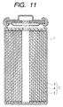
- Fig.11 is a sectional view showing the structure of a prior art cylindrical lithium ion secondary battery disclosed in JP-A-B-83608 (the term "JP-A" as used herein means an "unexamined published Japanese patent application”).
- 1 is an armor case made of stainless steel or the like which also serves as a negative electrode terminal
- 2 is an electrode body contained in the armor case 1
- the electrode body 2 has a structure in which a positive electrode 3, a separator 4 and a negative electrode 5 are coiled in a spiral shape.
- separator 4 and negative electrode 5 In order to maintain electric connection among respective surfaces of the positive electrode 3, separator 4 and negative electrode 5, it is necessary to apply external pressure to the electrode body 2.
- JP-A-5-159802 discloses a production method in which an ion conductive solid electrolyte layer and positive and negative electrodes are integrated into one body by their heat treatment using a thermoplastic resin binder.
- the electrodes are closely adhered to each other by integrating the positive and negative electrodes and the solid electrolyte layer into one body, so that electric connection among the positive and negative electrodes and the solid electrolyte layer is maintained and the integrated body functions as a battery without applying external force.
- a battery which uses a strong armor case to ensure adhesiveness and electric connection between positive and negative electrodes and a separator is disadvantageous in producing a battery having high energy density, because the ratio of volume and weight of the non-electricity generating part armor case to the entire battery portion becomes large.
- a method in which a positive electrode and a negative electrode are closely adhered to a separator via an adhesive resin has been proposed, it causes a problem in that ionic conduction resistance inside the battery cell increases and the battery characteristics are reduced due to large resistance of the adhesive resin layer, when a solid electrolyte layer (corresponds to the separator) is closely adhered to the positive and negative electrodes simply via the adhesive resin.
- the present invention has been accomplished as a result of intensive studies on the suitable bonding method of a separator and positive and negative electrodes, conducted by the present inventors with the aim of resolving the aforementioned problems, and it contemplates providing a lithium ion secondary battery having excellent charge and discharge characteristics, which can bond the positive and negative electrodes to the separator without increasing ionic conduction resistance between the positive and negative electrodes and without using a strong armor case, so that it has high energy density and can be made into a thin and optional shape.
- a first aspect of the lithium ion secondary battery of the present invention is a lithium ion secondary battery which comprises: a positive electrode active material layer bonded to a positive electrode collector; a negative electrode active material layer bonded to a negative electrode collector; a separator which has surfaces facing respective surfaces of said active material layers; and a lithium ion-containing electrolytic solution kept within said separator, said active material layers and therebetween, wherein convex and concave parts are formed on at least one of the facing surfaces of said positive active material layer and said separator, and at least one of the facing surfaces of said negative material layer and said separator, and two pairs of said facing surfaces are bonded by an adhesive resin layer respectively, so that voids having a predetermined depth are formed by a bonded surface of said convex parts and said concave parts, and the lithium ion-containing electrolytic solution are kept in the voids.
- a second aspect of the lithium ion secondary battery of the present invention is the battery according to the first aspect wherein the depth of voids is 30 ⁇ m or less.
- a third aspect of the lithium ion secondary battery of the present invention is the battery according to the second aspect wherein the depth of voids is 10 ⁇ m or less.
- a forth aspect of the lithium ion secondary battery of the present invention is the battery according to the first aspect wherein the area of bonded surface between respective surfaces is 10 to 30% of the total area of respective facing surfaces.
- a fifth aspect of the lithium ion secondary battery of the present invention is the battery according to the first aspect wherein bonding strength of each of positive and negative electrode active material layers with the separator is equal to or larger than respective bonding strength of each of the positive and negative electrode active material layers with each of the positive electrode collector and the negative electrode collector.
- a sixth aspect of the lithium ion secondary battery of the present invention is the battery according to the first aspect wherein the adhesive resin layer is porous.
- a seventh aspect of the lithium ion secondary battery of the present invention is the battery according to the first aspect wherein the adhesive resin layer is adhered between each of the positive and negative electrode active material layers and the separator partially .
- a eighth aspect of the lithium ion secondary battery of the present invention is the battery according to the first aspect wherein the convex and concave parts are formed on the surface of the positive and negative electrode active material layers.
- a ninth aspect of the lithium ion secondary battery of the present invention is the battery according to the seventh aspect wherein the adhesive resin layer is adhered only on the convex parts of the positive and negative electrode active material layers.
- a tenth aspect of the lithium ion secondary battery of the present invention is the battery according to the first aspect wherein the convex and concave parts are formed on the surface of the separator.
- a eleventh aspect of the lithium ion secondary battery of the present invention is the battery according to the seventh aspect wherein the adhesive resin layer is adhered selectively only on the bonded surface of said convex parts.
- a twelfth aspect of the lithium ion secondary battery of the present invention is the battery according to the first aspect wherein the convex and concave parts are formed on both surfaces of separator and the active material layers facing the separator regularly so that the convex parts on the separator and those on the active material layers are bonded each other through the adhesive resin layer.
- a thirteenth aspect of the lithium ion secondary battery of the present invention is the battery according to the first aspect wherein bonded regions of the separator with each of the active material layers are matched each other on both sides of the separator.
- a fourteenth aspect of the method of the present invention of fabricating a lithium ion secondary battery comprises steps of: adhering a positive electrode active material layer to a positive electrode collector; adhering a negative electrode active material layer to a negative electrode collector; forming convex parts and concave parts on at least one of a surface of the positive electrode active material layer and a surface of the separator facing to the positive electrode active material layer, and on at lest one of a surface of the negative electrode active material layer and a surface of the separator facing to the negative electrode active material layer; adhering the adhesive resin layer to at least one of the surface of the positive electrode active material layer and the facing surface of the separator and to at least one of the surface of the negative electrode active material layer and the facing surface of the separator; fitting one surface of the positive electrode active material layer and one surface of the negative electrode active material layer upon respective surfaces of said separator to form voids having a predetermined depth by a bonded surface of said convex parts and concave parts to form a laminated body; and
- a fifteenth aspect of the method of the present invention of fabricating a lithium ion secondary battery is the method according to the fourteenth aspect wherein the step of fitting comprises a step of heating a laminated body while pressing.
- a sixteenth aspect of the method of the present invention of fabricating a lithium ion secondary battery is the method according to the fourteenth aspect wherein the step of supplying comprises a step of dipping the laminated body into the lithium ion-containing electrolytic solution and a step of injecting them while reducing pressure of the lithium ion-containing electrolytic solution.
- a seventeenth aspect of the method of the present invention of fabricating a lithium ion secondary battery is the method according to the fourteenth aspect wherein the step of supplying further comprises a step of drying the laminated body while heating.
- a eighteenth aspect of the method of the present invention of fabricating a lithium ion secondary battery is the method according to the fourteenth aspect wherein the step of supplying comprises steps of: covering the laminated body with a flexible package; fitting air-tightly outsides of the laminated body to the flexible package by exhausting the flexible package; injecting the lithium ion-containing electrolytic solution from an opening of the flexible package into said separator, said active material layers and said therebetween including the voids in the laminated body; and sealing the opening of the flexible package.
- a nineteenth aspect of the method of the present invention of fabricating a lithium ion secondary battery is the method according to the eighteenth aspect wherein the flexible package is made of resin laminated aluminum and the step of sealing comprises a step of heat-pressing.
- a twelfth aspect of the method of the present invention of fabricating a lithium ion secondary battery is the method according to the fourteenth aspect wherein the step of adhering comprises a step of adhering the adhesive resin layer only on the convex parts of the positive and negative electrode active material layers locally so that the adhesive resin layer is adhered selectively only on the bonded surface of said convex parts.
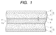
- Fig. 1 is a sectional view of the principal part showing a practical mode of the lithium ion secondary battery of the present invention.
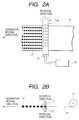
- Fig. 2 is an explanation drawing showing a method for coating an adhesive resin solution using a roller having minute openings, according to a practical mode of the present invention.
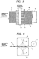
- Fig. 3 is an explanation drawing showing a method for coating an adhesive resin solution by screen printing as a practical mode of the present invention.
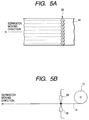
- Fig. 4 is an explanation drawing showing a method for coating an adhesive resin solution using a spray gun and a screen, as a practical mode of the present invention.
- Fig. 5 is an explanation drawing showing a method for coating an adhesive resin solution by a dispenser, as a practical mode of the present invention.
- Figs. 6A and 6B are a sectional illustration showing an example of the lithium ion secondary battery of the present invention and a magnification of magnifying a part of the lithium ion secondary battery.
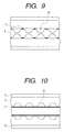
- Figs. 7 -10 are sectional illustration showing another examples of the lithium ion secondary battery of the present invention.
- Fig. 11 is a sectional view showing the structure of a prior art lithium ion secondary battery.
- 3 is a positive electrode
- 4 is a separator
- 5 is a negative electrode
- 6 is a positive electrode collector
- 7 is a positive electrode active material layer
- 9 is a negative electrode active material layer
- 10 is a negative electrode collector
- 11 is an adhesive resin layer
- 11a is a bonded surface
- 12 is void and L is depth of void.
- Fig. 1 is a sectional view of the principal part showing a practical mode of the lithium ion secondary battery of the present invention, in which 3 is a positive electrode prepared by bonding a positive electrode active material layer 7 to a positive electrode collector 6, 5 is a negative electrode prepared by bonding a negative electrode active material layer 9 to a negative electrode collector 10 and 4 is a separator which is arranged between the positive electrode 3 and negative electrode 5 and keeps a lithium ion-containing electrolytic solution, wherein convex parts and concave parts are formed on the surfaces of the separator 4 facing the active material layers 7, 9 and on the surfaces of the positive electrode active material layer 7 and negative electrode active material layer 9 adjacent (facing) to the facing surfaces of the separator 4.
- the part 11 is an adhesive resin layer which bonds the facing surfaces of separator 4 to the adjacent surfaces of active material layers 7, 9, thereby bonding these three members through its adhesion to the convex parts.
- 12 is voids having a predetermined depth L, which are formed between the electrodes (namely active material layers 7, 9) and the separator 4 by a bonded surface 11a of the convex parts and the concave parts, and a lithium ion-containing electrolytic solution is kept in the voids 12.
- convex and concave parts are formed on surfaces of the positive and negative electrode active material layers 7, 9 and the separator which becomes a electrolyte layer, and adhesiveness between the electrodes and separator is ensured by the convex parts of bonded surface 11a via the adhesive resin layer 11, so that it becomes possible to prevent peeling between the electrodes and separator, which was difficult to achieve in the conventional batteries.
- an electrolytic solution can be kept in the voids 12 which have a predetermined depth and are formed between them by the bonded surface 11a of the convex parts and the concave parts, so that excellent ion conductivity of the electrode-electrolyte interface can be ensured and ionic conduction resistance can be reduced.
- Coming and going quantity of ions in the active material layers inside the electrodes (positive and negative) and drift speed and drift quantity of ions into facing electrodes can be controlled to the same levels of the prior art lithium ion batteries which use armor cases. Electric connection between the active material layers 7, 9 and the separator 4 can be maintained without applying external force.
- a strong armor case is not required for keeping the battery structure, so that lightening and thinning of the battery can be made, optional shapes can be formed and excellent charge and discharge characteristics and battery performance can be obtained which are similar to those of the conventional batteries that use an electrolytic solution.
- the depth L of the voids 12 which are formed between the active material layers 7, 9 and the separator 4 by the bonded surface 11a of the convex parts and the concave parts varies depending on the conductivity of the electrolytic solution, but in the case of about 10 -2 S/cm which id usually used, it is desirable to adjust the depth to 30 ⁇ m or less because, if the depth is 30 ⁇ m or less, ionic conduction resistance between the active material layers 7, 9 and the separator 4 becomes sufficiently small which renders possible the use of the battery at a high load factor that does not fall behind those of the liquid electrolyte type batteries.
- the depth L of the voids 12 it is more desirable to adjust the depth L of the voids 12 to 10 ⁇ m or less, because dispersion of reaction species progresses more smoothly by adjusting the depth to 10 ⁇ m or less so that the ionic conduction resistance can be reduced more effectively. It is most desirable to adjust the depth L of the voids 12 to a few ⁇ m or less, because it is said that an adhesive layer (diffusion layer) of a few ⁇ m exists on the surface of the active material layers 7, 9 where the electrode reaction occurs, even when the solution is stirred, so that diffusion of reaction species seems to progress most smoothly when the depth L of the voids 12 is adjusted to this level or less.
- the area of the bonded surface 11a is 30% or less of the total area of respective facing surfaces of the active material layers 7, 9 and the separator 4, because, by adjusting the area to 30% or less, increase in the ion conductivity resistance between the active material layers 7, 9 and the separator 4 can be prevented so that the battery can be used at a large load factor which does not fall behind the prior art liquid electrolyte type batteries.
- bonding strength of the separator 4 with the positive and negative electrode active material layers 7, 9 becomes weak when the area of bonded surface 11a is adjusted to less than 10%, so that it is desirable that the area of bonded surface 11a between respective surfaces is adjusted to 10 to 30%, most preferably about 20%, of the total area of respective facing surfaces.
- the adhesive resin layer 11 when the adhesive resin layer 11 is porous, ionic conduction resistance in the adhesive resin layer and bonded parts can be reduced and resistance between the electrodes can be reduced. In addition, even if the adhesive resin layer 11 is adhered to all of the bonded surface 11a, both surfaces (facing surfaces) of the separator 4 or surfaces of the active material layers 7, 9 adjacent to the facing surfaces, ion conductivity can be ensured via minutes pores of the adhesive resin layer 11, so that coating of the adhesive resin layer 11 becomes easy.
- the ionic conduction resistance can further be reduced by forming voids to which the adhesive resin layer 11 is not adhered.
- the lithium ion secondary battery constructed in the aforementioned manner is produced by carrying out a step in which convex parts and concave parts are formed on at least two surfaces among one surface of the positive electrode active material layer 7, one surface of the negative electrode active material layer 9 and two facing surfaces of the separator 4, a step in which a resin layer is adhered to at least two surfaces among one surface of the positive electrode active material layer 7, one surface of the negative electrode active material layer 9 and two facing surfaces of the separator 4, and a step in which one surface of the positive electrode active material layer 7 and one surface of the negative electrode active material layer 9 are put upon respective surfaces of the separator 4 and adhered each other to form voids having a predetermined depth by the bonded surface 11a of the convex parts and the concave parts.
- the following methods can be exemplified as the means for locally adhering the adhesive resin layer 11 and the method for coating the adhesive resin on both sides of the separator 4 within a short period of time and in a large amount.
- Figs. 2A and B are an explanation drawing showing a method for coating an adhesive resin using a spin roller having minute pores on its surface, in which Fig. 2A is a plan view and Fig. 2B is a side view.
- An adhesive resin is filled within the spin roller 13 having minute pores 13a on its surface and the adhesive resin is extruded through the minutes pores 13a by applying a pressure to the inner portion of the spin roller 13 using a pressurizer 16.
- the entire spin roller 13 is rotated while moving a separator material 14 supplied from a separator roller 15, thereby coating the adhesive resin 17 in dots on both sides of the separator material 14.
- FIG. 3 there is a method for the coating of an adhesive resin in which a screen through which openings are bored in dots or lines and a spin roller are used.
- a caterpillar-like screen 19 through which openings 19a are bored in dots is arranged close to the surface of a separator material 14, an adhesive resin 17 is dropped from an adhesive resin dropping outlet 20 on the screen 19 arranged on the moving separator material 14 and then the thus supplied adhesive resin is rolled using a spin roller 21, thereby transferring a pattern of the adhesive resin 17, which reflects the shape of the openings 19a of the screen 19, onto the separator material 14.
- the adhesive resin can be coated in dots on both sides of the separator material 14.
- FIG. 4 is an explanation drawing showing a method for coating an adhesive resin using a spray gun.
- a caterpillar-like screen 26 through which openings are bored in a dot, line or lattice form is arranged close to the surface of a separator material 14, and a liquid adhesive resin or a adhesive resin solution prepared by dissolving an adhesive resin in a solvent is packed in a spray gun 23 and then sprayed on the separator material 14 through the screen 26.
- the adhesive resin 17 is adhered to the separator material 14 according to the shape of openings of the screen 26, for example in a dotted pattern.
- the adhesive resin can be coated in a dotted pattern on both sides of the separator material 14, by arranging at least one spray gun 23 on each side of the separator material 14 and continuously spraying the adhesive resin solution while moving the separator material 14.
- a net or the like may be used in stead of the screen 26.
- an adhesive resin may be coated in a dotted pattern by arranging at least one or more of a dispenser 28 packed with an adhesive resin solution on a separator material 14 and dropping the adhesive resin solution intermittently in concert with the movement of a separator 27.
- Fig. 5A in the drawing is a plan view and Fig. 5B is a side view.
- complex oxides of lithium with cobalt, nickel, manganese and the like transition metals, lithium-containing chalcogen compounds or complex compounds thereof, as well as these complex oxides, lithium-containing chalcogen compounds or complex compounds thereof further having additional elements may be used in the positive electrode, and easy-graphitized carbon, hard-graphitized carbon, polyacene, polyacetylene and the like carbonaceous compounds and pyrene, perylene and the like acene structure-containing aromatic hydrocarbon compounds may be used preferably in the negative electrode.
- any other material may also be used with the proviso that it can occlude and release lithium ion which becomes the core of the battery actuation.
- these active materials are used in a granular form, and their useful particle size is 0.3 to 20 ⁇ m, most preferably 0.3 to 5 ⁇ m.
- any resin can be used, provided that it is insoluble in the electrolytic solution and does not generate electrochemical reactions in the laminated electrode body. Its illustrative examples include vinylidene fluoride, ethylene fluoride, acrylonitrile, ethylene oxide and the like homopolymers or copolymers thereof and ethylene propylene diamine rubber.
- any metal which is stable in the battery can be used as the collector, but aluminum is preferably used in the positive electrode and copper in the negative electrode.
- foil, net, expand metal and the like shapes can be employed, but net, expand metal or the like shape having a large void area is desirable in terms of its feasibility to keep the electrolytic solution after bonding.
- any material can be used as the separator, with the proviso that it is electron insulating material having sufficient strength, such as a porous membrane, a net, non-woven fabric or the like.
- electron insulating material having sufficient strength
- its construction material is not particularly limited, polyethylene or polypropylene is desirable from the viewpoint of adhesiveness and safety.
- non-aqueous solvents and lithium-containing electrolyte salts used in conventional batteries can be used.
- the solvent include dimethoxyethane, diethoxyethane, diethyl ether, dimethyl ether and the like ether solvents and propylene carbonate, ethylene carbonate, diethyl carbonate, dimethyl carbonate and the like ester solvents, which may be used as a single solution or as a mixture solution of two of the same or different solvents.
- Illustrative examples of the electrolyte salt include LiPF 6 , LiAsF 6 , LiClO 4 , LiBF 4 , LiCF 3 SO 3 , LiN(CF 3 SO 2 ) 2 , LiC(CF 3 SO 2 ) 3 , LiN(C 2 F 5 SO 2 ) 2 and the like.
- any resin can be used as the adhesive resin to be used in the adhesion of collectors and electrodes, with the proviso that it is insoluble in the electrolytic solution and does not generate electrochemical reactions in the battery similar to the case of the adhesive resin to be used in the adhesion of electrodes and separator, but a resin which becomes porous membrane is more desirable.
- Its illustrative examples include vinylidene fluoride, 4-ethylene fluoride and the like polymers which has fluorine atom in its molecular structure, or their mixtures with methyl polymethacrylate, polystyrene, polyethylene, polypropylene and the like.
- a positive electrode active material paste prepared by dispersing 87 parts by weight of LiCoO 2 , 8 parts by weight of graphite powder and 5 parts by weight of polyvinylidene fluoride in N-methylpyrrolidone was coated in a thickness of 300 ⁇ m by the doctor blade method to form an active material thin film.
- An aluminum net having a thickness of 30 ⁇ m to be used as a positive electrode collector was put on the film, on which was again coated the positive electrode active material paste prepared to a thickness of 300 ⁇ m by the doctor blade method, thereby preparing a laminated body of the positive electrode collector and positive electrode active material paste.
- the laminate was made into a half-dried state by allowing it to stand for 60 minutes in an oven of 60°C, and then the laminate was rolled to a thickness of 400 ⁇ m using a spin roller whose roll clearance has been adjusted to 400 ⁇ m, thereby preparing a positive electrode having convex and concave parts on the surface of the positive electrode active material layer 7.
- a spin roller whose roll clearance has been adjusted to 400 ⁇ m, thereby preparing a positive electrode having convex and concave parts on the surface of the positive electrode active material layer 7.
- thickness of the electrode and degree of the irregularity can be adjusted by adjusting roll clearance of the spin roller in the rolling step.
- the shape of irregularity formed on the surface of the positive electrode active material layer 7 can be changed by changing shapes (mesh size, mesh roughness, opening area rate and the like) of the net to be used as the positive electrode collector.
- the thus prepared positive electrode was soaked in an electrolytic solution and then peel strength of the positive electrode active material layer and positive electrode collector was measured. As a measured peel strength, value of 20 to 25 gf/cm is obtained.
- a negative electrode active material paste prepared by dispersing 95 parts by weight of Meso-Phase-Microbeads Carbon (trade name: manufactured by Osaka Gas) and 5 parts by weight of polyvinylidene fluoride in N-methylpyrrolidone (to be referred to as NMP hereinafter) was coated in a thickness of 300 ⁇ m by the doctor blade method to form an active material thin film.
- a copper net having a thickness of 20 ⁇ m to be used as a negative electrode collector was put on the film, on which was again coated the negative electrode active material paste prepared to a thickness of 300 ⁇ m by the doctor blade method, thereby preparing a laminated body of the negative electrode collector and negative electrode active material paste.
- the laminate was made into a half-dried state by allowing it to stand for 60 minutes in an oven of 60°C, and then the laminate was closely adhered by rolling it to a thickness of 400 ⁇ m using a spin roller whose roll clearance has been adjusted to 400 ⁇ m, thereby preparing a negative electrode having convex and concave parts on the surface of the negative electrode active material layer 9. Similar to the case of the positive electrode, convex and concave parts reflecting the shape of the net can be formed on the surface of the negative electrode active material layer 9, by sandwiching the copper net as the collector in stead of planer copper foil.
- the thus prepared negative electrode was soaked in an electrolytic solution and then peel strength of the negative electrode active material layer and negative electrode collector was measured. As a measured peel strength, a value of 10 to 15 gf/cm is obtained.
- a viscous adhesive resin solution was prepared by mixing 5 parts by weight of polyvinylidene fluoride and 95 parts by weight of N-methylpyrrolidone (to be referred to as NMP hereinafter) at that compositional ratio and thoroughly stirring the mixture until it became uniform solution.
- NMP N-methylpyrrolidone
- a separator material to be used as a separator namely a rolled-up porous polypropylene sheet (trade name Cell Guard #2400, manufactured by Hoechst) having a width of 12 cm and a thickness of 25 ⁇ m.
- a separator material 14 was took out from a separator roll 15 and sandwiched by the spin roller 13 having minute openings 13a on its surface.
- the spin roller 13 has such a structure that the aforementioned adhesive resin solution is filled in its inside portion and oozed out through the minute openings 13a on its surface. It was able to coat the adhesive resin 17 in a dotted pattern on both sides of the separator material 14 by applying pressure to the inside of the spin roller 13 having minute openings 13a and simultaneously rotating the roller. Also, it was able to control coating mass of the adhesive resin by changing its discharge from the minute openings 13a through the adjustment of inner pressure of the spin roller 13.
- the positive and negative electrode active material layers 7, 9 were closely adhered and laminated in such a way that they faced each other sandwiching the separator, thereby obtaining an electrode laminate.
- the thus pasted electrode laminate was allowed to stand for 2 hours in a hot air dryer of 60°C to effect evaporation of NMP.
- the adhesive resin layer 17 becomes a porous film (adhesive resin layer) which has voids communicating from the separator side into the positive and negative electrode sides.
- This adhesive resin layer was adjusted to a thickness of about 1 ⁇ m.
- an electrolytic solution prepared using ethylene carbonate and diethyl carbonate as the solvent and LiPF 6 as the solute was injected into the electrode laminate.
- the injecting step is performed by dipping the electrode laminate in the electrolytic solution kept at a low pressure.
- peel strengths of the positive electrode active material and separator and of the negative electrode active material and separator were measured at this stage, the strengths were 25 to 30 gf/cm and 15 to 20 gf/cm, respectively.
- FIG. 6 is a sectional illustration showing an example of the lithium ion secondary battery of this invention.
- 30 is an armor aluminum laminate pack and 8 is the electrode laminate sealed in the armor aluminum laminate pack.
- the electrode laminate 8 is composed of a positive electrode 3, a separator 4 and a negative electrode 5.
- convex and concave parts are formed on the surfaces of the separator 4 facing both of the active material layers 7, 9 and on the surfaces adjacent to the surfaces of the separator 4 facing the positive electrode active material layer 7 and negative electrode active material layer 9, so that the positive electrode 3, separator 4 and negative electrode 5 are closely adhered via the adhesive resin layer 11 which is adhered to the bonded surface 11a of the convex parts, and a lithium ion-containing electrolytic solution is kept in the voids 12 which are formed by the bonded surface 11a of the convex parts and the concave parts (generated in response to the surface irregularity when the electrodes are adhered to the separator).
- the active material layers 7, 9 and the separator 4 are not completely covered with the adhesive resin layer 11 and the electrolytic solution is kept in the voids 12, increase in the internal resistance between the active material layers 7, 9 and the separator 4 is prevented and excellent ionic conductivity is secured, and the bonding strength of the active material layers 7, 9 with the separator 4 is maintained by the bonded surface 11a of the convex parts of the adhesive resin layer 11, thus rendering possible production of a thin and light battery having excellent charge and discharge characteristics, which does not require external pressurization, namely which does not require a strong armor case.
- the convex and concave parts are formed on both surfaces of separator 4 and the active material layers 3,7 facing the separator regularly and the convex parts on the separator and those on the active material layers are bonded each other through the adhesive resin layer. And bonded regions of the separator with each of the active material layers are matched each other on both sides of the separator 4. According to the structure, in the case that a large force is supplied to the bonded surface, strong bonding strength is kept.
- bonded regions of the separator with each of the active material layers can be formed so as to deviate each other on both sides of the separator 4.
- a twisting force is applied to the separator. Therefore, the bond is easy to being destroyed in comparison with the structure as shown in Fig.6B.
- convex parts and concave parts are formed both surfaces of the separator and the active material layers.
- convex parts and concave parts can be formed only on the surface of the positive and negative active material layers.
- fluoride resin film whose surfaces are roughened so as to have convex parts and concave parts can be used as a separator, and active material layers having plane surfaces are used as the positive and negative active material layers.
- an adhesive resin layer 11 is formed only on a bonded region, however as shown in fig.10, an adhesive resin layer 11 is formed on a whole facing surface.
- adhesive resin layer is formed only on a bonded region, it is required that positions of convex parts on the positive and negative active material layers are matched to the coating positions of adhesive material layer.
- the lithium ion-containing electrolytic solution can be supplied effectively.
- the laminated body is dried by heating, after being supplied.
- a lithium ion secondary battery can be fabricated by the method as follows. After mounting the laminated body, the laminated body is covered with a flexible package; fitted air-tightly outsides of the laminated body to the flexible package by exhausting the flexible package; injected the lithium ion-containing electrolytic solution from an opening of the flexible package into said separator, said active material layers and said therebetween including the voids in the laminated body; and sealing the opening of the flexible package.
- the lithium ion-containing electrolytic solution when the lithium ion-containing electrolytic solution is injected, back side of the negative and positive electrode collector is covered with the flexible package air-tightly, therefore the lithium ion-containing electrolytic solution is prevented to be reached to the backward of the negative and positive electrode collector and unrequired solution not depend to the electrolytic operation is not injected. So total weight of the lithium ion secondary battery can be reduced.
- viscous adhesive resin solutions were used which have been prepared by mixing N-methylpyrrolidone with each of the following compounds 1-9 in stead of polyvinylidene fluoride at the same compositional ratio as Embodiment 1 respectively.
- the electrode laminate 8 was prepared by the same method of Embodiment 1 respectively.
- peel strengths of the positive electrode active material layer 7 and separator 4 and of the negative electrode active material layer 9 and separator 4 in this electrode laminate 8 were measured, the strengths were converged at 15 to 70 gf/cm and 10 to 70 gf/cm, respectively.
- lithium ion batteries were prepared by injecting an electrolytic solution, packing with an aluminum laminate film and sealing the opening in the same manner as described in Embodiment 1. Similar to the case of Embodiment 1, thin and light batteries having excellent charge and discharge characteristics were obtained.
- a positive electrode active material paste was coated in a thickness of 300 ⁇ m by the doctor blade method on an aluminum net having a thickness of 30 ⁇ m and an opening area rate of 70%, allowed to stand for 60 minutes in a dryer of 60°C and then again pressed to a thickness of 250 ⁇ m, thereby obtaining the positive electrode 3.
- the negative electrode 5 was prepared in the same manner using a copper net, an adhesive resin was partially coated in a dotted pattern by the same method described in Embodiment 1 and then the positive electrode 3, the separator 4 and the negative electrode 5 were closely adhered to one another to prepare an electrode laminate. Since the void depth L of the electrode laminate 8 of this example was adjusted to 10 ⁇ m or less, dispersion of the reaction species progresses easily and the ionic conduction resistance of the interfaces between the active material layers 7, 9 and the separator can be reduced, so that the lithium ion secondary battery produced using this laminate can be used at a large load factor which does not fall behind those of the conventional liquid electrolyte type batteries.
- the depth L of the voids 12 can be controlled for example by the rolling pressure at the time of the formation of the positive and negative electrodes or the mesh size of the net.
- a positive electrode active material paste was coated in a thickness of 300 ⁇ m by the doctor blade method on an aluminum net having a thickness of 30 ⁇ m and an opening area rate of 80%, allowed to stand for 60 minutes in a dryer of 60°C and then again pressed to a thickness of 200 ⁇ m, thereby obtaining the positive electrode 3 in which convex parts and concave parts were formed on the surface of the active material layer 7.
- the negative electrode 5 was prepared in the same manner using a copper net. Convex parts and concave parts were also formed on the surface of the negative electrode active material layer 9.
- an adhesive resin was coated by the same method described in Embodiment 1 and then the positive electrode 3, the separator 4 and the negative electrode 5 were closely adhered to one another to prepare the electrode laminate 8.
- area of the bonded surface 11a was adjusted to 20% of the total area of each of the active material layers 7, 9. Since the coated portion of the adhesive resin layer was 20%, increase in the ionic conduction resistance between the active material layers 7, 9 was able to be prevented, so that the battery was able to be used at a large load factor which did not fall behind those of the conventional liquid electrolyte type batteries.
- the area of the bonded surface 11a can be adjusted based on the surface shapes of the active material layers 7, 9 and the separator 4, which are controlled by mesh size, opening area rate and the like of the net, and coating (adhering) conditions of the adhesive resin.
- a positive electrode active material paste was coated in a thickness of 300 ⁇ m by the doctor blade method on an aluminum net having a thickness of 30 ⁇ m and an opening area rate of 80%, allowed to stand for 60 minutes in a dryer of 60°C and then again pressed to a thickness of 250 ⁇ m, thereby obtaining the positive electrode 3 in which convex parts and concave parts were formed on the surface of the active material layer 7.
- the negative electrode 5 was prepared in the same manner using a panting metal made of copper, in which convex parts and concave parts were formed on the surface of the active material layer 9.
- the depth L of the voids 12 formed between the active material layers 7, 9 and the separator 4 by the bonded surface 11a of the convex parts and the concave parts was adjusted to 10 ⁇ m or less.
- the void depth L can be controlled for example by the rolling pressure at the time of the electrode formation or the opening area rate, opening shape and the like of the panting metal.
- a positive electrode active material paste was coated in a thickness of 300 ⁇ m by the doctor blade method on an aluminum panting metal collector material having a thickness of 30 ⁇ m and an opening area rate of 80%, allowed to stand for 60 minutes in a dryer of 60°C and then again pressed to a thickness of 200 ⁇ m, thereby obtaining the positive electrode 3 in which convex parts and concave parts were formed on the surface of the active material layer 7.
- the negative electrode 5 was prepared in the same manner using a copper panting metal in which convex parts and concave parts were also formed on the surface of the negative electrode active material layer 9.
- an adhesive resin was coated by the same method described in Embodiment 1 and then the positive electrode 3, the separator 4 and the negative electrode 5 were closely adhered to one another to prepare the electrode laminate 8. Since the area of the bonded surface 11a between the active material layers 7, 9 and the separator was adjusted to 20% of the total area of each of the active material layers 7, 9 in this method, increase in the ionic conduction resistance between the active material layers 7, 9 and the separator was able to be prevented, or the resistance was able to be reduced in other words, so that the battery was able to be used at a large load factor which did not fall behind those of the conventional liquid electrolyte type batteries.
- a positive electrode active material paste was coated in a thickness of 300 ⁇ m by the doctor blade method on an aluminum foil collector material having a thickness of 30 ⁇ m and allowed to stand for 60 minutes in a dryer of 60°C, and an expanded metal having a thickness of 30 ⁇ m and an opening area rate of 20% was pressed on the surface of the active material paste and then the expanded metal was removed from the surface.
- an active material layer 7 which has convex and concave parts having a depth of 30 ⁇ m on the surface thereof are formed . And subsequently the thus treated active material layer 7 are pressed to a total thickness of 250 ⁇ m to form the positive electrode 3.
- the negative electrode 5 was prepared in the same manner using a copper foil collector material.
- the depth L of the voids 12 formed between the active material layers 7, 9 and the separator 4 by the concave parts on the surface of the active material layers 7, 9 was adjusted to 10 ⁇ m or less.
- a positive electrode active material paste was coated in a thickness of 300 ⁇ m by the doctor blade method on an aluminum foil collector material having a thickness of 30 ⁇ m and allowed to stand for 60 minutes in a dryer of 60°C, and an panting metal having a thickness of 30 ⁇ m and an opening area rate of 20% was pressed on the surface of the active material paste and the panting metal was then removed from the surface.
- an active material layer 7 which has convex and concave parts having a depth of 30 ⁇ m are formed on the surface thereof. And subsequently the thus treated active material layer 7 are pressed to a total thickness of 250 ⁇ m to form the positive electrode 3.
- the negative electrode 5 was prepared in the same manner using a copper foil collector material.
- an adhesive resin was coated by the same method described in Embodiment 1 and then the positive electrode 3, the separator 4 and the negative electrode 5 were closely adhered to one another to prepare the electrode laminate 8. Since the area of the bonded surface 11a between the active material layers 7, 9 and the separator 4 was adjusted to 20% of the total area of the active material layers 7, 9 in this method, increase in the ionic conduction resistance between the active material layers 7, 9 and the separator 4 was able to be prevented so that the battery was able to be used at a high load factor which did not fall behind those of the conventional liquid electrolyte type batteries.
- a rolled-up porous polypropylene sheet (trade name Cell Guard #2400, manufactured by Hoechst) having a width of 12 cm and a thickness of 25 ⁇ m to be used as a separator material 14 was took out, and a caterpillar-like screen 19 in which openings 19a having a diameter of 100 ⁇ m have been bored in a dotted pattern was pressed on the separator material 14.
- the adhesive resin solution shown in Embodiment 1 was applied dropwise on the screen 19, and the adhesive resin was rolled on the screen with a coating roller 21, thereby effecting transfer and coating of the adhesive resin solution in a dotted pattern on the separator.
- the separator material was twisted to an angle of 180 degree to transfer and coat the adhesive resin on the un-coated side of the separator, which enabled coating of the adhesive resin 17 on both sides of the separator material 14.
- the adhesive resin solution shown in Embodiment 2 was used, it was able also to coat the adhesive resin suitably on both sides of the separator material 14 in a dotted pattern.
- a lithium secondary battery having excellent characteristics similar to the case of Embodiments 1 to 8 was obtained even by the use of a separator material 14 to which an adhesive resin layer was adhered.
- a rolled-up porous polypropylene sheet (trade name Cell Guard #2400, manufactured by Hoechst) having a width of 12 cm and a thickness of 25 ⁇ m to be used as a separator material 14 was took out, and the separator 14 was sandwiched between two caterpillar-like screens 26 in which openings have been bored in a dotted pattern.
- the adhesive resin solution was sprayed on the separator material 14.
- this spraying method it was able to coat the adhesive resin solution in a dotted pattern on both sides of the separator material 14. Also, it was able to control coating mass of the adhesive resin by changing the spray velocity.
- Embodiment 2 When the adhesive resin solution shown in Embodiment 2 was used, it was able also to coat the adhesive resin solution properly on both sides of the separator material 14 in a dotted pattern. Also, a lithium secondary battery having excellent characteristics was obtained by the use of a separator to which an adhesive resin layer was adhered.
- a rolled-up porous polypropylene sheet (trade name Cell Guard #2400, manufactured by Hoechst) having a width of 12 cm and a thickness of 25 ⁇ m to be used as a separator material 14 was took out, and the adhesive resin solution shown in Embodiment 1 was filled in 8 on one side, 16 in total, of dispensers 28 arranged on both sides of the separator material 14. It was able to coat the adhesive resin solution in a dotted pattern, by dropping the thus prepared adhesive resin solution intermittently on the surface of the separator material 14 simultaneously with the movement of the separator material 14. When the adhesive resin solution shown in Embodiment 2 was used, it was able also to coat the adhesive resin solution properly on both sides of the separator material 14. Also, a lithium secondary battery having excellent characteristics was obtained by the use of a separator material 14 to which an adhesive resin layer was adhered.
- the battery is equipped with a positive electrode active material layer bonded to a positive electrode collector, a negative electrode active material layer bonded to a negative electrode collector and a separator which has surfaces facing respective surfaces of said active material layers and keeps a lithium ion-containing electrolytic solution, in which convex and concave parts formed on said facing surfaces or on the surface of each of said active material layers adjacent to said facing surfaces are bonded by an adhesive resin layer to each of said facing surfaces and the surface of each of said active material layers adjacent to said facing surfaces, thus having voids of a predetermined depth formed by a bonded surface of said convex parts and said concave parts and also having a lithium ion-containing electrolytic solution kept in the voids, so that adhesiveness between the positive and negative electrode active material layers and the separator can be secured by the bonded surface of convex parts and proper ion conductivity between the positive and negative electrode active material layers and the separator can be secured by the electrolytic solution kept in
- the depth of voids according to the first aspect is adjusted to 30 ⁇ m or less, so that dispersion of the reaction species progresses easily and the ionic conduction resistance between the positive and negative electrode active material layers and the separator can therefore be reduced, thus rendering possible its use at a large load factor which does not fall behind the conventional liquid electrolyte type batteries.
- the depth of voids is adjusted to 10 ⁇ m or less, so that diffusion of the reaction species progresses more easily, thus rendering possible its use at a higher load factor.
- the area of bonded surface between respective surfaces according to the first aspect is adjusted to 10 to 30% of the total area of respective facing surfaces, so that increase in the ionic conduction resistance between the positive and negative electrode active material layers and the separator can be repressed, thus rendering possible its use at a large load factor which does not fall behind the conventional liquid electrolyte type batteries.
- bonding strengths between the separator and the positive and negative electrode active material layers according to the first aspect are equal to or larger than respective bonding strengths between the positive electrode collector and the positive electrode active material layer and the negative electrode collector and the negative electrode active material layer, so that destruction of the electrodes (peeling of the active material layers from the collectors) occurs taking preference over peeling between the active material layers and the separator. Also, adhesiveness between the active material layers and the separator can be fully secured and maintained without using a strong armor case
- the adhesive resin layer according to the first aspects is in a porous form, so that resistance between the positive and negative electrodes can be kept at a low level.
- voids to which the adhesive resin layer is not adhered are formed in the first aspect, so that increase in the ionic conduction resistance can further be repressed.
- the method of the present invention for the production of a lithium ion secondary battery, it comprises a step of forming convex parts and concave parts on at least two surfaces among one surface of the positive electrode active material layer, one surface of the negative electrode active material layer and two facing surfaces of the separator, a step of adhering the adhesive resin layer to at least two surfaces among one surface of the positive electrode active material layer, one surface of the negative electrode active material layer and two facing surfaces of the separator, and a step of putting one surface of the positive electrode active material layer and one surface of the negative electrode active material layer upon respective surfaces of said separator and pressing them to form voids having a predetermined depth by a bonded surface of said convex parts and said concave parts, so that it exerts an effect in obtaining excellent lithium ion secondary batteries simply and easily with good workability.
- resistance between the positive and negative electrodes inside the battery can be kept at a low level by locally adhering the adhesive resin layer to effect formation of voids to which the adhesive resin layer is not adhered.
Landscapes
- Chemical & Material Sciences (AREA)
- Engineering & Computer Science (AREA)
- Manufacturing & Machinery (AREA)
- Chemical Kinetics & Catalysis (AREA)
- Electrochemistry (AREA)
- General Chemical & Material Sciences (AREA)
- Dispersion Chemistry (AREA)
- Materials Engineering (AREA)
- Secondary Cells (AREA)
- Battery Electrode And Active Subsutance (AREA)
- Cell Separators (AREA)
Abstract
Description
Claims (20)
wherein convex and concave parts are formed on at least one of the facing surfaces of said positive active material layer (7) and said separator (4), and on at least one of the facing surfaces of said negative material layer (9) and said separator (4), and two pairs of said facing surfaces are bonded by an adhesive resin layer (11) respectively, so that voids (12) having a predetermined depth are formed at the bonded surface by said convex parts and said concave parts, and the lithium ion-containing electrolytic solution is held in said voids (12).
Applications Claiming Priority (3)
| Application Number | Priority Date | Filing Date | Title |
|---|---|---|---|
| JP337099/96 | 1996-12-17 | ||
| JP33709996A JP3303694B2 (en) | 1996-12-17 | 1996-12-17 | Lithium ion secondary battery and method of manufacturing the same |
| JP33709996 | 1996-12-17 |
Publications (2)
| Publication Number | Publication Date |
|---|---|
| EP0849819A2 true EP0849819A2 (en) | 1998-06-24 |
| EP0849819A3 EP0849819A3 (en) | 2003-09-24 |
Family
ID=18305435
Family Applications (1)
| Application Number | Title | Priority Date | Filing Date |
|---|---|---|---|
| EP97121267A Withdrawn EP0849819A3 (en) | 1996-12-17 | 1997-12-03 | Lithium ion secondary battery and method of fabricating thereof |
Country Status (4)
| Country | Link |
|---|---|
| US (1) | US5981107A (en) |
| EP (1) | EP0849819A3 (en) |
| JP (1) | JP3303694B2 (en) |
| KR (1) | KR100287004B1 (en) |
Cited By (13)
| Publication number | Priority date | Publication date | Assignee | Title |
|---|---|---|---|---|
| EP0982789A1 (en) * | 1998-03-17 | 2000-03-01 | Mitsubishi Denki Kabushiki Kaisha | Lithium ion battery and method of manufacture thereof |
| EP0994522A2 (en) * | 1998-10-13 | 2000-04-19 | Samsung Display Devices Co., Ltd. | Lithium polymer battery |
| WO2000060690A1 (en) * | 1999-03-31 | 2000-10-12 | Koninklijke Philips Electronics N.V. | Method of bonding a separator and an electrode, more particularly a cathode or an anode, as well as a battery |
| WO2008058757A1 (en) * | 2006-11-17 | 2008-05-22 | Li-Tec Vermögensverwaltungs GmbH | Electrode arrangement for a battery or secondary battery |
| WO2009125272A1 (en) * | 2008-04-07 | 2009-10-15 | Toyota Jidosha Kabushiki Kaisha | Negative electrode element for lithium-ion secondary battery, lithium-ion secondary battery and method of manufacturing the same |
| US7759004B2 (en) * | 2003-12-12 | 2010-07-20 | Panasonic Corporation | Electrode for lithium ion secondary batteries, lithium ion secondary battery using the same, and method for manufacturing the battery |
| CN102035015A (en) * | 2009-09-24 | 2011-04-27 | 大日本网屏制造株式会社 | Battery manufacturing method and battery |
| EP2696395A1 (en) * | 2011-04-06 | 2014-02-12 | LG Chem, Ltd. | Separator and electrochemical device including same |
| US20140106213A1 (en) * | 2011-06-28 | 2014-04-17 | Murata Manufacturing Co., Ltd. | Electrical storage device element and electrical storage device |
| US9276247B2 (en) | 2011-04-06 | 2016-03-01 | Lg Chem, Ltd. | Separator and electrochemical device comprising the same |
| EP3033784A4 (en) * | 2013-08-15 | 2017-03-15 | Robert Bosch GmbH | Li/metal cell with structured surface separator |
| CN109935761A (en) * | 2018-11-13 | 2019-06-25 | 万向一二三股份公司 | A kind of lithium ion battery composite pole piece and preparation method thereof |
| CN115149108A (en) * | 2021-03-30 | 2022-10-04 | 宁德新能源科技有限公司 | Electrochemical device and electronic device |
Families Citing this family (88)
| Publication number | Priority date | Publication date | Assignee | Title |
|---|---|---|---|---|
| JP3481797B2 (en) * | 1996-10-03 | 2003-12-22 | 片山特殊工業株式会社 | Method for manufacturing battery electrode substrate and battery electrode substrate |
| JP3225864B2 (en) | 1996-12-04 | 2001-11-05 | 三菱電機株式会社 | Lithium ion secondary battery and method of manufacturing the same |
| DE964468T1 (en) * | 1997-01-27 | 2000-06-08 | Kanebo, Ltd. | ORGANIC, ELECTROLYTIC BATTERY |
| JPH10284131A (en) | 1997-02-04 | 1998-10-23 | Mitsubishi Electric Corp | Lithium ion secondary battery and its manufacture |
| CN1192445C (en) * | 1997-04-23 | 2005-03-09 | 日本电池株式会社 | Electrode and battery |
| FR2766296B1 (en) * | 1997-07-17 | 1999-08-20 | Alsthom Cge Alcatel | METHOD FOR MANUFACTURING AN ELECTROCHEMICAL GENERATOR WITH UNIT STRUCTURE |
| US6225010B1 (en) * | 1997-11-19 | 2001-05-01 | Mitsubishi Denki Kabushiki Kaisha | Lithium ion secondary battery and manufacture thereof |
| KR100397043B1 (en) * | 1997-11-19 | 2003-09-02 | 미쓰비시덴키 가부시키가이샤 | Lithium ion secondary battery and manufacture thereof |
| JP3475759B2 (en) * | 1997-12-11 | 2003-12-08 | 松下電器産業株式会社 | Non-aqueous electrolyte secondary battery |
| EP1043796A4 (en) | 1997-12-18 | 2003-05-02 | Mitsubishi Electric Corp | Manufacture of lithium ion secondary battery |
| KR20010033603A (en) * | 1997-12-25 | 2001-04-25 | 다니구찌 이찌로오, 기타오카 다카시 | Lithium ion secondary battery |
| JP3426253B2 (en) | 1998-01-19 | 2003-07-14 | 三菱電機株式会社 | Battery |
| US6811928B2 (en) | 1998-01-22 | 2004-11-02 | Mitsubishi Denki Kabushiki Kaisha | Battery with adhesion resin layer including filler |
| WO1999040639A1 (en) | 1998-02-06 | 1999-08-12 | Mitsubishi Denki Kabushiki Kaisha | Electrode, method for manufacturing thereof, and battery using the electrode |
| JP3428452B2 (en) * | 1998-08-27 | 2003-07-22 | 三菱電機株式会社 | Battery with spiral electrode body and method of manufacturing the same |
| JP3980505B2 (en) * | 1998-08-31 | 2007-09-26 | 株式会社東芝 | Thin lithium ion secondary battery |
| JP4031405B2 (en) * | 1998-09-17 | 2008-01-09 | 株式会社東芝 | Non-aqueous electrolyte secondary battery |
| US6146791A (en) * | 1998-11-25 | 2000-11-14 | Materials And Electrochemical Research (Mer) Corporation | Hydrogenated fullerenes as an additive to carbon anode for rechargeable lithium-ion batteries |
| US6485862B1 (en) | 1998-12-28 | 2002-11-26 | Mitsubishi Denki Kabushiki Kaisha | Thin battery and method of manufacturing |
| KR20000066416A (en) * | 1999-04-16 | 2000-11-15 | 김순택 | lithum polymer battery and manufacturing method thereof |
| EP1115166A4 (en) | 1999-06-22 | 2004-09-15 | Mitsubishi Electric Corp | Separator for cell, cell, and method for producing separator |
| US6376125B2 (en) | 1999-07-19 | 2002-04-23 | Mitsubishi Denki Kabushiki Kaisha | Lithium ion secondary battery and process for producing the same |
| US20030170536A1 (en) * | 1999-09-22 | 2003-09-11 | Mitsubishi Denki Kabushiki Kaisha | Bttery with adhesion resin layer including filler |
| JP2004500686A (en) | 1999-12-09 | 2004-01-08 | 日本特殊陶業株式会社 | Lithium ion battery separator and / or lithium ion polymer battery |
| JP2001176497A (en) * | 1999-12-15 | 2001-06-29 | Sanyo Electric Co Ltd | Nonaqueous electrolyte secondary battery |
| WO2001056097A1 (en) | 2000-01-24 | 2001-08-02 | Mitsubishi Denki Kabushiki Kaisha | Package for nonaqueous electrolyte cell and cell comprising the same |
| EP1273058B1 (en) | 2000-03-24 | 2008-07-30 | Cymbet Corporation | Method for producing a thin-film battery having an ultra-thin electrolyte |
| US6432586B1 (en) | 2000-04-10 | 2002-08-13 | Celgard Inc. | Separator for a high energy rechargeable lithium battery |
| KR100789558B1 (en) | 2000-06-07 | 2007-12-28 | 상요 지에스 소프트 에너지 가부시끼가이샤 | Battery |
| KR20020000015A (en) * | 2000-06-20 | 2002-01-04 | 김순택 | Lithium secondary cell and method thereof |
| US6482544B1 (en) | 2000-06-30 | 2002-11-19 | Mitsubishi Denki Kabushiki Kaisha | Battery package |
| KR100337707B1 (en) * | 2000-09-25 | 2002-05-22 | 정근창 | Pocketed electrode plate for use in lithium ion secondary battery, its manufacturing method and lithium ion secondary battery using the same |
| US7037621B2 (en) * | 2000-11-01 | 2006-05-02 | Sony Corporation | Cell, cell production method, welded article production method and pedestal |
| US6727017B1 (en) | 2001-04-06 | 2004-04-27 | Changs Ascending Enterprise Co., Ltd. | Methods of fabricating binding layers for a Li-ion polymer battery |
| KR20030047040A (en) * | 2001-12-07 | 2003-06-18 | 삼성에스디아이 주식회사 | Lithium battery |
| JP4053003B2 (en) * | 2001-12-21 | 2008-02-27 | 三洋電機株式会社 | Nonaqueous electrolyte secondary battery |
| JP2003217673A (en) * | 2002-01-23 | 2003-07-31 | Japan Storage Battery Co Ltd | Non-aqueous electrolyte secondary battery and manufacturing method for it |
| US6803545B2 (en) * | 2002-06-05 | 2004-10-12 | Philip Morris Incorporated | Electrically heated smoking system and methods for supplying electrical power from a lithium ion power source |
| US6906436B2 (en) | 2003-01-02 | 2005-06-14 | Cymbet Corporation | Solid state activity-activated battery device and method |
| TWI244789B (en) * | 2003-08-01 | 2005-12-01 | Hon Hai Prec Ind Co Ltd | A battery and make same |
| JP4601338B2 (en) * | 2004-06-24 | 2010-12-22 | 日東電工株式会社 | Battery positive electrode / reactive polymer-supported porous film / negative electrode laminate |
| KR100601550B1 (en) * | 2004-07-28 | 2006-07-19 | 삼성에스디아이 주식회사 | Lithium Ion Secondary battery |
| JP4526352B2 (en) | 2004-11-08 | 2010-08-18 | 日東電工株式会社 | Reactive polymer-supported porous film for battery separator and battery manufacturing method using the same |
| JP4833064B2 (en) * | 2005-03-31 | 2011-12-07 | 富士重工業株式会社 | Lithium ion capacitor |
| WO2007011899A2 (en) | 2005-07-15 | 2007-01-25 | Cymbet Corporation | Thin-film batteries with polymer and lipon electrolyte layers and method |
| US7776478B2 (en) | 2005-07-15 | 2010-08-17 | Cymbet Corporation | Thin-film batteries with polymer and LiPON electrolyte layers and method |
| US20070172735A1 (en) * | 2006-01-26 | 2007-07-26 | David R. Hall | Thin-film Battery |
| KR100914108B1 (en) * | 2007-05-03 | 2009-08-27 | 삼성에스디아이 주식회사 | Electrode assembly and rechargeable battery with the same |
| US8852787B2 (en) * | 2007-09-28 | 2014-10-07 | A123 Systems Llc | Batteries having inorganic/organic porous films |
| US8377583B2 (en) * | 2008-01-30 | 2013-02-19 | Lg Chem, Ltd. | Separator for providing a uniting force to electrode and electrochemical cell containing the same |
| DE112010000853T5 (en) * | 2009-01-12 | 2012-12-06 | A123 Systems, Inc. | Laminated battery cell and method for its production |
| US8470468B2 (en) | 2010-02-12 | 2013-06-25 | GM Global Technology Operations LLC | Lithium-ion batteries with coated separators |
| KR101101695B1 (en) * | 2010-06-10 | 2011-12-30 | 삼성전기주식회사 | Electrolyte for Lithium ion capacitor and Lithium ion capacitor comprising the same |
| US9583757B2 (en) | 2010-12-22 | 2017-02-28 | Enevate Corporation | Electrodes, electrochemical cells, and methods of forming electrodes and electrochemical cells |
| JP6044083B2 (en) * | 2011-06-21 | 2016-12-14 | 日産自動車株式会社 | Multilayer battery and manufacturing method thereof |
| JP5610076B2 (en) * | 2011-06-28 | 2014-10-22 | 株式会社村田製作所 | Electric storage device and manufacturing method thereof |
| US11996517B2 (en) | 2011-06-29 | 2024-05-28 | Space Charge, LLC | Electrochemical energy storage devices |
| US11527774B2 (en) | 2011-06-29 | 2022-12-13 | Space Charge, LLC | Electrochemical energy storage devices |
| US10601074B2 (en) | 2011-06-29 | 2020-03-24 | Space Charge, LLC | Rugged, gel-free, lithium-free, high energy density solid-state electrochemical energy storage devices |
| US9853325B2 (en) | 2011-06-29 | 2017-12-26 | Space Charge, LLC | Rugged, gel-free, lithium-free, high energy density solid-state electrochemical energy storage devices |
| US9142837B2 (en) * | 2011-09-09 | 2015-09-22 | SCREEN Holdings Co., Ltd. | Lithium ion secondary battery and preparation process of same |
| JP5910164B2 (en) * | 2012-02-28 | 2016-04-27 | 日産自動車株式会社 | Nonaqueous electrolyte secondary battery |
| WO2013133025A1 (en) * | 2012-03-06 | 2013-09-12 | ソニー株式会社 | Separator, battery, battery pack, electronic device, electric vehicle, electricity storage device and electric power system |
| JP6110700B2 (en) * | 2012-03-29 | 2017-04-05 | 株式会社半導体エネルギー研究所 | Method for producing lithium ion secondary battery |
| JP2014013702A (en) * | 2012-07-04 | 2014-01-23 | Nitto Denko Corp | Electrode for electricity storage device, electricity storage device including the same, and method for manufacturing the electrode |
| US20150147627A1 (en) * | 2013-11-25 | 2015-05-28 | Samsung Sdi Co., Ltd. | Rechargeable lithium battery |
| US9761854B2 (en) * | 2013-12-13 | 2017-09-12 | Samsug SDI Co., Ltd. | Spirally-wound electrode assembly for rechargeable lithium battery and rechargeable lithium battery including same |
| US9761874B2 (en) * | 2013-12-30 | 2017-09-12 | Verily Life Sciences Llc | Fabrication methods for batteries |
| KR101822593B1 (en) * | 2015-03-17 | 2018-01-26 | 주식회사 엘지화학 | Electrode having porous binder coating layer, method for preparation thereof, and lithium secondary battery comprising the same |
| DE102015010440B4 (en) * | 2015-08-11 | 2023-10-26 | Cellcentric Gmbh & Co. Kg | Method and device for producing a membrane-electrode arrangement for a fuel cell |
| JP2017054792A (en) * | 2015-09-11 | 2017-03-16 | 日本碍子株式会社 | Lithium battery |
| JP2017073328A (en) * | 2015-10-09 | 2017-04-13 | 日立マクセル株式会社 | Nonaqueous electrolyte secondary battery |
| KR101950086B1 (en) * | 2016-03-15 | 2019-02-19 | 가부시끼가이샤 도시바 | Non-aqueous electrolyte battery, battery pack and vehicle |
| US20200303743A1 (en) * | 2016-05-25 | 2020-09-24 | Nec Corporation | Electrode for battery, battery having electrode and method for manufacturing electrode and battery having electrode |
| KR102207524B1 (en) * | 2016-09-01 | 2021-01-26 | 주식회사 엘지화학 | Methode of preparing electrodes for lithium secondary battery and the electrodes for lithium secondary battery manufactured by the same |
| WO2018134961A1 (en) * | 2017-01-20 | 2018-07-26 | 日産自動車株式会社 | Method for manufacturing mono cell |
| WO2019034143A1 (en) * | 2017-08-18 | 2019-02-21 | Shanghai Energy New Materials Technology Co., Ltd. | Separators and electrochemical devices comprising the separator |
| JP7162187B2 (en) * | 2017-11-29 | 2022-10-28 | パナソニックIpマネジメント株式会社 | Non-aqueous electrolyte secondary battery |
| US10686214B2 (en) | 2017-12-07 | 2020-06-16 | Enevate Corporation | Sandwich electrodes and methods of making the same |
| US11133498B2 (en) | 2017-12-07 | 2021-09-28 | Enevate Corporation | Binding agents for electrochemically active materials and methods of forming the same |
| US20190181431A1 (en) * | 2017-12-07 | 2019-06-13 | Enevate Corporation | Solid film as binder for battery electrodes |
| KR102204304B1 (en) | 2017-12-27 | 2021-01-18 | 주식회사 엘지화학 | Li metal secondary battery and method for fabricating the same |
| EP3762989A4 (en) | 2018-03-07 | 2021-12-15 | Space Charge, LLC | Thin-film solid-state energy-storage devices |
| JP6973244B2 (en) * | 2018-03-30 | 2021-11-24 | トヨタ自動車株式会社 | Non-aqueous electrolyte secondary battery and method for manufacturing non-aqueous electrolyte secondary battery |
| JP7209660B2 (en) * | 2020-03-13 | 2023-01-20 | パナソニックホールディングス株式会社 | BATTERY MANUFACTURING METHOD AND BATTERY |
| EP4089824A4 (en) * | 2021-03-30 | 2023-05-10 | Ningde Amperex Technology Ltd. | Electrochemical device and electronic device |
| CN116830348A (en) * | 2023-02-03 | 2023-09-29 | 宁德新能源科技有限公司 | Secondary battery and electronic device |
| CN116830347A (en) * | 2023-03-30 | 2023-09-29 | 宁德新能源科技有限公司 | Secondary battery and electronic device |
Citations (6)
| Publication number | Priority date | Publication date | Assignee | Title |
|---|---|---|---|---|
| JPS61214364A (en) * | 1985-03-19 | 1986-09-24 | Hitachi Maxell Ltd | Thin lithium battery |
| JPH0443572A (en) * | 1990-06-08 | 1992-02-13 | Brother Ind Ltd | Secondary battery |
| JPH05109429A (en) * | 1991-10-14 | 1993-04-30 | Ricoh Co Ltd | Laminated body having electron conductor layer and ion conductor layer and its manufacture |
| JPH06333550A (en) * | 1993-05-19 | 1994-12-02 | Toshiba Corp | Nonaqueous electrolytic battery |
| US5437692A (en) * | 1994-11-02 | 1995-08-01 | Dasgupta; Sankar | Method for forming an electrode-electrolyte assembly |
| US5605550A (en) * | 1993-06-14 | 1997-02-25 | Valence Technology, Inc. | Battery laminate with improved electrolyte and anode or cathode layer characteristics |
Family Cites Families (2)
| Publication number | Priority date | Publication date | Assignee | Title |
|---|---|---|---|---|
| US5460904A (en) * | 1993-08-23 | 1995-10-24 | Bell Communications Research, Inc. | Electrolyte activatable lithium-ion rechargeable battery cell |
| US5498489A (en) * | 1995-04-14 | 1996-03-12 | Dasgupta; Sankar | Rechargeable non-aqueous lithium battery having stacked electrochemical cells |
-
1996
- 1996-12-17 JP JP33709996A patent/JP3303694B2/en not_active Expired - Fee Related
-
1997
- 1997-12-03 EP EP97121267A patent/EP0849819A3/en not_active Withdrawn
- 1997-12-12 KR KR1019970068201A patent/KR100287004B1/en not_active IP Right Cessation
- 1997-12-15 US US08/990,764 patent/US5981107A/en not_active Expired - Fee Related
Patent Citations (6)
| Publication number | Priority date | Publication date | Assignee | Title |
|---|---|---|---|---|
| JPS61214364A (en) * | 1985-03-19 | 1986-09-24 | Hitachi Maxell Ltd | Thin lithium battery |
| JPH0443572A (en) * | 1990-06-08 | 1992-02-13 | Brother Ind Ltd | Secondary battery |
| JPH05109429A (en) * | 1991-10-14 | 1993-04-30 | Ricoh Co Ltd | Laminated body having electron conductor layer and ion conductor layer and its manufacture |
| JPH06333550A (en) * | 1993-05-19 | 1994-12-02 | Toshiba Corp | Nonaqueous electrolytic battery |
| US5605550A (en) * | 1993-06-14 | 1997-02-25 | Valence Technology, Inc. | Battery laminate with improved electrolyte and anode or cathode layer characteristics |
| US5437692A (en) * | 1994-11-02 | 1995-08-01 | Dasgupta; Sankar | Method for forming an electrode-electrolyte assembly |
Non-Patent Citations (4)
| Title |
|---|
| PATENT ABSTRACTS OF JAPAN vol. 011, no. 051 (E-480), 17 February 1987 (1987-02-17) & JP 61 214364 A (HITACHI MAXELL LTD), 24 September 1986 (1986-09-24) * |
| PATENT ABSTRACTS OF JAPAN vol. 016, no. 230 (E-1208), 27 May 1992 (1992-05-27) & JP 04 043572 A (BROTHER IND LTD), 13 February 1992 (1992-02-13) * |
| PATENT ABSTRACTS OF JAPAN vol. 017, no. 460 (E-1419), 23 August 1993 (1993-08-23) -& JP 05 109429 A (RICOH CO LTD), 30 April 1993 (1993-04-30) * |
| PATENT ABSTRACTS OF JAPAN vol. 095, no. 003, 28 April 1995 (1995-04-28) & JP 06 333550 A (TOSHIBA CORP), 2 December 1994 (1994-12-02) * |
Cited By (19)
| Publication number | Priority date | Publication date | Assignee | Title |
|---|---|---|---|---|
| EP0982789A1 (en) * | 1998-03-17 | 2000-03-01 | Mitsubishi Denki Kabushiki Kaisha | Lithium ion battery and method of manufacture thereof |
| EP0982789A4 (en) * | 1998-03-17 | 2003-09-10 | Mitsubishi Electric Corp | Lithium ion battery and method of manufacture thereof |
| EP0994522A2 (en) * | 1998-10-13 | 2000-04-19 | Samsung Display Devices Co., Ltd. | Lithium polymer battery |
| EP0994522A3 (en) * | 1998-10-13 | 2001-09-19 | Samsung Display Devices Co., Ltd. | Lithium polymer battery |
| US6737196B2 (en) | 1998-10-13 | 2004-05-18 | Samsung Display Devices Co., Ltd. | Method of making a lithium polymer battery and battery made by the method |
| WO2000060690A1 (en) * | 1999-03-31 | 2000-10-12 | Koninklijke Philips Electronics N.V. | Method of bonding a separator and an electrode, more particularly a cathode or an anode, as well as a battery |
| US7759004B2 (en) * | 2003-12-12 | 2010-07-20 | Panasonic Corporation | Electrode for lithium ion secondary batteries, lithium ion secondary battery using the same, and method for manufacturing the battery |
| WO2008058757A1 (en) * | 2006-11-17 | 2008-05-22 | Li-Tec Vermögensverwaltungs GmbH | Electrode arrangement for a battery or secondary battery |
| WO2009125272A1 (en) * | 2008-04-07 | 2009-10-15 | Toyota Jidosha Kabushiki Kaisha | Negative electrode element for lithium-ion secondary battery, lithium-ion secondary battery and method of manufacturing the same |
| CN102035015A (en) * | 2009-09-24 | 2011-04-27 | 大日本网屏制造株式会社 | Battery manufacturing method and battery |
| CN102035015B (en) * | 2009-09-24 | 2013-11-20 | 大日本网屏制造株式会社 | Battery manufacturing method and battery |
| EP2696395A1 (en) * | 2011-04-06 | 2014-02-12 | LG Chem, Ltd. | Separator and electrochemical device including same |
| EP2696395A4 (en) * | 2011-04-06 | 2014-10-29 | Lg Chemical Ltd | Separator and electrochemical device including same |
| US9276247B2 (en) | 2011-04-06 | 2016-03-01 | Lg Chem, Ltd. | Separator and electrochemical device comprising the same |
| US20140106213A1 (en) * | 2011-06-28 | 2014-04-17 | Murata Manufacturing Co., Ltd. | Electrical storage device element and electrical storage device |
| US9728343B2 (en) * | 2011-06-28 | 2017-08-08 | Murata Manufacturing Co., Ltd. | Electrical storage device element and electrical storage device |
| EP3033784A4 (en) * | 2013-08-15 | 2017-03-15 | Robert Bosch GmbH | Li/metal cell with structured surface separator |
| CN109935761A (en) * | 2018-11-13 | 2019-06-25 | 万向一二三股份公司 | A kind of lithium ion battery composite pole piece and preparation method thereof |
| CN115149108A (en) * | 2021-03-30 | 2022-10-04 | 宁德新能源科技有限公司 | Electrochemical device and electronic device |
Also Published As
| Publication number | Publication date |
|---|---|
| US5981107A (en) | 1999-11-09 |
| KR19980064085A (en) | 1998-10-07 |
| KR100287004B1 (en) | 2001-04-16 |
| EP0849819A3 (en) | 2003-09-24 |
| JPH10172537A (en) | 1998-06-26 |
| JP3303694B2 (en) | 2002-07-22 |
Similar Documents
| Publication | Publication Date | Title |
|---|---|---|
| US5981107A (en) | Lithium ion secondary battery and method of fabricating thereof | |
| US6322599B1 (en) | Method of fabricating a lithium ion secondary battery | |
| EP0851522B1 (en) | Method of fabricating a lithium ion secondary battery | |
| EP0959513B1 (en) | Lithium ion secondary battery and manufacture thereof | |
| EP0852406B1 (en) | Lithium ion secondary battery and method of fabricating thereof | |
| KR100397043B1 (en) | Lithium ion secondary battery and manufacture thereof | |
| EP0982790A1 (en) | Lithium ion battery and method for forming the same | |
| EP1652246A2 (en) | Secondary cell electrode and fabrication method, and secondary cell, complex cell, and vehicle | |
| JP3474853B2 (en) | Manufacturing method of lithium ion secondary battery | |
| US6352797B1 (en) | Lithium ion battery and method for forming the same | |
| US20010009736A1 (en) | Lithium ion secondary battery and process for producing the same | |
| KR100329296B1 (en) | Lithium ion battery and method for forming the same | |
| KR100300531B1 (en) | Lithium ion secondary battery and method of fabricating thereof | |
| KR100301995B1 (en) | Lithium ion secondary battery and its manufacture | |
| JP2003151631A (en) | Method of manufacturing lithium ion polymer battery and lithium ion polymer battery obtained by this method |
Legal Events
| Date | Code | Title | Description |
|---|---|---|---|
| PUAI | Public reference made under article 153(3) epc to a published international application that has entered the european phase |
Free format text: ORIGINAL CODE: 0009012 |
|
| AK | Designated contracting states |
Kind code of ref document: A2 Designated state(s): AT BE CH DE DK ES FI FR GB GR IE IT LI LU MC NL PT SE |
|
| AX | Request for extension of the european patent |
Free format text: AL;LT;LV;MK;RO;SI |
|
| PUAL | Search report despatched |
Free format text: ORIGINAL CODE: 0009013 |
|
| AK | Designated contracting states |
Kind code of ref document: A3 Designated state(s): AT BE CH DE DK ES FI FR GB GR IE IT LI LU MC NL PT SE |
|
| AX | Request for extension of the european patent |
Extension state: AL LT LV MK RO SI |
|
| RIC1 | Information provided on ipc code assigned before grant |
Ipc: 7H 01M 4/04 B Ipc: 7H 01M 10/40 A |
|
| AKX | Designation fees paid | ||
| REG | Reference to a national code |
Ref country code: DE Ref legal event code: 8566 |
|
| STAA | Information on the status of an ep patent application or granted ep patent |
Free format text: STATUS: THE APPLICATION IS DEEMED TO BE WITHDRAWN |
|
| 18D | Application deemed to be withdrawn |
Effective date: 20040325 |