EP0849398A1 - Paver - Google Patents
Paver Download PDFInfo
- Publication number
- EP0849398A1 EP0849398A1 EP97121397A EP97121397A EP0849398A1 EP 0849398 A1 EP0849398 A1 EP 0849398A1 EP 97121397 A EP97121397 A EP 97121397A EP 97121397 A EP97121397 A EP 97121397A EP 0849398 A1 EP0849398 A1 EP 0849398A1
- Authority
- EP
- European Patent Office
- Prior art keywords
- machine frame
- paver
- area
- crawler tracks
- screed
- Prior art date
- Legal status (The legal status is an assumption and is not a legal conclusion. Google has not performed a legal analysis and makes no representation as to the accuracy of the status listed.)
- Granted
Links
Images

Classifications
-
- E—FIXED CONSTRUCTIONS
- E01—CONSTRUCTION OF ROADS, RAILWAYS, OR BRIDGES
- E01C—CONSTRUCTION OF, OR SURFACES FOR, ROADS, SPORTS GROUNDS, OR THE LIKE; MACHINES OR AUXILIARY TOOLS FOR CONSTRUCTION OR REPAIR
- E01C19/00—Machines, tools or auxiliary devices for preparing or distributing paving materials, for working the placed materials, or for forming, consolidating, or finishing the paving
- E01C19/48—Machines, tools or auxiliary devices for preparing or distributing paving materials, for working the placed materials, or for forming, consolidating, or finishing the paving for laying-down the materials and consolidating them, or finishing the surface, e.g. slip forms therefor, forming kerbs or gutters in a continuous operation in situ
Definitions
- the invention relates to a paver according to the preamble of claim 1.
- Ceiling paver (DE-A-4101417), the screed for floating Have installation, are usually for a layer thickness up to about 30 cm, measured behind the screed of the paver. Only in rare cases is the basic design of the paver a larger layer thickness is provided. The reason for this is there in that for a greater layer thickness the conveyor belt of the paver finisher at least in the rear area of the machine and the auger as well as the conveyor shaft and the screed transport cylinders along with all of them Superstructures that are above the screed can be arranged higher have to. As paver to the respective construction site using a low loader are transported, usually also bridge underpasses happened is the transport height, usually determined by Weather roof or cabin superstructures, limited accordingly for portability to ensure.
- the object of the invention is to provide a paver after Generic preamble of claim 1 to create the without major retooling is convertible to an increased layer thickness without the risk there is interference due to material being conveyed forward again occur.
- crawler tracks of the paver finisher are in theirs front area rotatably mounted on the machine frame and in the rear area height adjustable with respect to the machine frame so that the rear Area of the conveyor is raised.
- the adjustment can be extreme done quickly and reversed just as quickly.
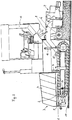
- Fig. 1 shows a paver in side view during installation a thin layer.
- Fig. 2 shows a paver in side view during installation a layer of great thickness.
- the paver shown comprises a machine frame 1 with side crawler tracks 2.
- a bucket 3 with side unfoldable side wall parts 4 are provided, which on corresponding, underneath, fixed side wall parts 5 articulated are, in order to unfold a hopper for to be installed To form material.
- a circumferential, usually with cross bars provided conveyor forms the bottom of the bucket 3 and Conveys filled material to the rear of the machine frame 1 in the area of a screw auger 6 located there, which the material distributed over the pave width.
- the material so distributed will by means of a screed 7, which can be used laterally to widen is extendable and / or can be cut, under compression and smoothing built-in.
- the screed 7 floating on the material to be installed is articulated via draw arms 8 on the machine frame 1 and via actuating cylinders 9 in relation to a desired installation height of the material to be installed height adjustable.
- the screed 7 can ramming and / or vibration units 10, 11 include.
- the screed 7 is via a screed transport cylinder 12 into one suitable for transporting the paver finisher Position can be raised.
- the crawler tracks 2 are in the area of their front third mounted on the machine frame 1 so as to be rotatable about an axis 14. In her rear Area are the crawler tracks 2 compared to a vertical sliding guide 15, which is firmly connected to the machine frame 1, vertically adjustable. For the starting position from which the machine frame 1 can be raised against the crawler tracks 2 at the rear, a stop be provided.
- the vertical adjustment of the crawler tracks 2 compared to that Machine frame 1 can be made using screw spindles, for example will.
- corresponding hydraulic actuating cylinders 16, one for each crawler track 2, preferably, for example, about the hydraulic circuit already present in a paver using of a four / three-way valve electrohydraulically controlled and in the desired position via an unlockable twin check valve can be held.
- the rear part can be set in an extremely short time of the paver including the screed 7 in one opposite Bring the lane 17 higher position. Then they are all there Units such as screed 7, conveyor, auger 6, screed transport cylinder 12 and the superstructure above the screed 7 in an advantageous one for a large layer thickness of the ceiling to be installed Location. Due to the higher position of the screed transport cylinder 12, the Paving screed 7 should therefore be built up in accordance with large layer thicknesses.
Abstract
Die Erfindung betrifft einen Deckenfertiger mit einem Maschinenrahmen (1)
und Raupenfahrwerken (2), wobei der Maschinenrahmen (1) vorderseitig einen Kübel (3)
und rückseitig eine Verteilerschnecke (6) aufweist, zwischen denen ein Förderer
zum Transportieren von einzubauendem Material aus dem Kübel (3) durch
einen Förderschacht, über dem sich Aufbauten (13) befinden, in den Bereich
der Verteilerschnecke (6) angeordnet ist, während eine Einbaubohle (7) über Zugarme (8)
am Maschinenrahmen (1) angelenkt hinter dem Bereich der Verteilerschnecke (6)
zum schwimmenden Einbau des einzubauenden Materials vorgesehen
ist, bei dem die Raupenfahrwerke (2) in ihrem vorderen Bereich (14) drehbar am
Maschinenrahmen (1) gelagert und in ihrem hinteren Bereich längs einer am
Maschinenrahmen befindlichen Vertikalführung (16) höhenverstellbar angeordnet
sind.

Description
Die Erfindung betrifft einen Deckenfertiger nach dem Oberbegriff
des Anspruchs 1.The invention relates to a paver according to the preamble
of
Deckenfertiger (DE-A-4101417), die Einbaubohlen zum schwimmenden Einbau aufweisen, werden üblicherweise für eine Schichtdicke bis etwa 30 cm, gemessen hinter der Einbaubohle des Deckenfertigers, ausgelegt. Nur in seltenen Fällen wird bei der Grundauslegung des Deckenfertigers eine größere Schichtdicke vorgesehen. Der Grund hierfür besteht darin, daß für eine größere Schichtdicke das Förderband des Deckenfertigers zumindest im hinteren Maschinenbereich und die Verteilerschnecke sowie der Förderschacht und die Bohlentransportzylinder nebst sämtlichen Aufbauten, die oberhalb der Einbaubohle liegen, höher angeordnet werden müssen. Da Deckenfertiger zur jeweiligen Baustelle mittels Tieflader transportiert werden, wobei gewöhnlich auch Brückenunterführungen zu passieren sind, ist die Transporthöhe, gewöhnlich bestimmt durch Wetterdach- oder Kabinenaufbauten, entsprechend limitiert, um die Transportierbarkeit zu gewährleisten.Ceiling paver (DE-A-4101417), the screed for floating Have installation, are usually for a layer thickness up to about 30 cm, measured behind the screed of the paver. Only in rare cases is the basic design of the paver a larger layer thickness is provided. The reason for this is there in that for a greater layer thickness the conveyor belt of the paver finisher at least in the rear area of the machine and the auger as well as the conveyor shaft and the screed transport cylinders along with all of them Superstructures that are above the screed can be arranged higher have to. As paver to the respective construction site using a low loader are transported, usually also bridge underpasses happened is the transport height, usually determined by Weather roof or cabin superstructures, limited accordingly for portability to ensure.
Für Anwendungsfälle mit außergewöhnlichen Schichtdicken (z.B. bis 50 cm) werden daher in der Regel die vorgenannten Elemente nur für diesen Sonderfall insgesamt nach oben versetzt, um sie nach Erledigung der Baumaßnahme wieder rückgängig zu machen. Bereits diese Maßnahmen sind mit einem erheblichen Montageaufwand verbunden und führen zudem dazu, daß die Querstege des Untertrums des Förderbandes Material vom Verteilerschneckenraum wieder nach vorne unter den Fertiger fördern, da der Freiraum unterhalb des Untertrums des Förderers in seiner Höhe nicht entsprechend vergrößert ist. Dies führt zu entsprechenden Störungen, die sogar zu einem Einbaustillstand führen können.For applications with exceptional layer thicknesses (e.g. up to 50 cm), the above-mentioned elements are therefore usually only for this special case altogether shifted to them after settlement to undo the construction work. Already these measures are associated with a considerable assembly effort and also lead to that the crossbars of the lower run of the conveyor belt material from the screw chamber convey forward again under the paver because the There is no free space below the lower run of the conveyor is enlarged accordingly. This leads to corresponding disturbances can even lead to installation downtime.
Aufgabe der Erfindung ist es, einen Deckenfertiger nach dem
Oberbegriff des Anspruchs 1 zu schaffen, der ohne großen Umrüstaufwand
auf einen erhöhten Schichtdickeneinbau umstellbar ist, ohne daß die Gefahr
besteht, daß Störungen durch wieder nach vorne gefördertes Material
auftreten.The object of the invention is to provide a paver after
Generic preamble of
Diese Aufgabe wird entsprechend dem kennzeichnenden Teil des
Anspruchs 1 gelöst.This task is performed according to the characteristic part of the
Hierbei sind die Raupenfahrwerke des Deckenfertigers in ihrem vorderen Bereich drehbar am Maschinenrahmen gelagert und im hinteren Bereich in bezug auf den Maschinenrahmen höhenverstellbar, so daß der hintere Bereich des Förderers angehoben wird. Die Verstellung kann äußerst schnell erfolgen und ebenso schnell rückgängig gemacht werden.Here the crawler tracks of the paver finisher are in theirs front area rotatably mounted on the machine frame and in the rear area height adjustable with respect to the machine frame so that the rear Area of the conveyor is raised. The adjustment can be extreme done quickly and reversed just as quickly.
Weitere Ausgestaltungen dar Erfindung sind der nachfolgenden Beschreibung und den Unteransprüchen zu entnehmen.Further refinements of the invention are as follows Description and the dependent claims.
Die Erfindung wird nachstehend anhand eines in der beigefügten Abbildung schematisiert dargestellten Ausführungsbeispiels näher erläutert.The invention is illustrated below in the attached Figure illustrated schematically illustrated embodiment.
Fig. 1 zeigt einen Deckenfertiger in Seitenansicht beim Einbau einer Schicht geringer Dicke.Fig. 1 shows a paver in side view during installation a thin layer.
Fig. 2 zeigt einen Deckenfertiger in Seitenansicht beim Einbau einer Schicht großer Dicke.Fig. 2 shows a paver in side view during installation a layer of great thickness.
Der dargestellte Deckenfertiger umfaßt ein Maschinenrahmen 1
mit seitlichen Raupenfahrwerken 2. Frontseitig ist ein Kübel 3 mit seitlich
auseinanderklappbaren Seitenwandteilen 4 vorgesehen, die an entsprechenden,
darunter befindlichen, feststehenden Seitenwandteilen 5 angelenkt
sind, um auseinandergeklappt einen Einfülltrichter für einzubauendes
Material zu bilden. Ein umlaufender, gewöhnlich mit Querstegen
versehener Förderer (nicht dargestellt) bildet den Boden des Kübels 3
und Fördert eingefülltes Material zur Rückseite des Maschinenrahmens 1
in den Bereich einer dort befindlichen Verteilerschnecke 6, die das Material
über die Einbaubreite verteilt. Das so verteilte Material wird
mittels einer Einbaubohle 7, die gegebenenfalls zum Verbreitern seitlich
ausfahrbar und/oder anstückelbar ist, unter Verdichten und Glätten
eingebaut. Die auf dem einzubauenden Material schwimmende Einbaubohle 7
ist über Zugarme 8 am Maschinenrahmen 1 angelenkt und über Stellzylinder
9 in bezug auf eine gewünschte Einbauhöhe des einzubauenden Materials
höhenverstellbar. Die Einbaubohle 7 kann Stampf- und/oder Vibrationsaggregate
10, 11 umfassen. Die Einbaubohle 7 ist über einen Bohlentransportzylinder
12 in eine zum Transport des Deckenfertigers geeignete
Stellung anhebbar. Über dem Förderschacht des Förderers sind Aufbauten
mit einem Fahrerstand 13, einem Antriebsmotor und dergleichen angeordnet.The paver shown comprises a
Die Raupenfahrwerke 2 sind im Bereich ihres vorderen Drittels
um eine Achse 14 drehbar am Maschinenrahmen 1 gelagert. In ihrem hinteren
Bereich sind die Raupenfahrwerke 2 gegenüber einer vertikalen Gleitführung
15, die fest mit dem Maschinenrahmen 1 verbunden ist, vertikal
verstellbar. Für die Ausgangsstellung, aus der der Maschinenrahmen 1
hinten gegenüber den Raupenfahrwerken 2 anhebbar ist, kann ein Anschlag
vorgesehen sein.The
Die vertikale Verstellung der Raupenfahrwerke 2 gegenüber dem
Maschinenrahmen 1 kann beispielsweise mittels Schraubspindeln vorgenommen
werden. Jedoch werden entsprechende hydraulische Stellzylinder 16,
jeweils einer pro Raupenfahrwerk 2, bevorzugt, die beispielsweise über
den bei einem Deckenfertiger ohnehin vorhandenen Hydraulikkreislauf mittels
eines Vier-/Dreiwegeventils elektrohydraulisch gesteuert und in der
jeweils gewünschten Position über ein entsperrbares Zwillingsrückschlagventil
gehalten werden können.The vertical adjustment of the
Hierdurch läßt sich in äußerst kurzer Zeit der hintere Teil
des Deckenfertigers einschließlich der Einbaubohle 7 in eine gegenüber
dem Fahrbahngrund 17 erhöhte Position bringen. Dann befinden sich sämtliche
Aggregate wie Einbaubohle 7, Förderer, Verteilerschnecke 6, Bohlentransportzylinder
12 und die Aufbauten oberhalb der Einbaubohle 7 in
eine für eine große Schichtdicke der einzubauenden Decke vorteilhaften
Lage. Durch die höhere Position des Bohlentransportzylinders 12 kann die
Einbaubohle 7 somit entsprechend große Schichtdicken einbauen.As a result, the rear part can be set in an extremely short time
of the paver including the screed 7 in one opposite
Bring the
Durch den Hub der Stellzylinder 16 wird allerdings die minimale
Höhe einer einbaubaren Schichtdicke im Verhältnis zur maximalen limitiert.
Wenn nach einer Schicht mit entsprechend großer Schichtdicke wiederum
Normalbeläge wie ca. 4 cm dicke Verschleißbeläge oder ca. 8 cm
dicke Binderschichten eingebaut werden sollen, sind die Raupenfahrwerke
2 und damit der Maschinenrahmen 1 über die Stellzylinder 16 wieder entsprechend
abzusenken. Allerdings kann dies ebenfalls sehr schnell vorgenommen
werden, so daß keine langwierigen Umrüstarbeiten entstehen.Due to the stroke of the actuating
Claims (3)
Applications Claiming Priority (2)
| Application Number | Priority Date | Filing Date | Title |
|---|---|---|---|
| DE19652396 | 1996-12-17 | ||
| DE19652396A DE19652396C1 (en) | 1996-12-17 | 1996-12-17 | Ceiling production unit with machine frame and continuous track chassis |
Publications (2)
| Publication Number | Publication Date |
|---|---|
| EP0849398A1 true EP0849398A1 (en) | 1998-06-24 |
| EP0849398B1 EP0849398B1 (en) | 2003-09-03 |
Family
ID=7814934
Family Applications (1)
| Application Number | Title | Priority Date | Filing Date |
|---|---|---|---|
| EP97121397A Expired - Lifetime EP0849398B1 (en) | 1996-12-17 | 1997-12-05 | Paver |
Country Status (6)
| Country | Link |
|---|---|
| EP (1) | EP0849398B1 (en) |
| JP (1) | JP3042679B2 (en) |
| CN (1) | CN1174145C (en) |
| DE (2) | DE19652396C1 (en) |
| ES (1) | ES2206645T3 (en) |
| RU (1) | RU2193619C2 (en) |
Cited By (5)
| Publication number | Priority date | Publication date | Assignee | Title |
|---|---|---|---|---|
| CN101974879A (en) * | 2010-11-02 | 2011-02-16 | 三一重工股份有限公司 | Automatic positioning device in lifting of large arm of spreader and spreader |
| EP3498913A1 (en) | 2017-12-13 | 2019-06-19 | Joseph Vögele AG | Road finisher with raisable chassis |
| EP3498915A1 (en) | 2017-12-13 | 2019-06-19 | Joseph Vögele AG | Road finisher with raisable chassis |
| EP3498916A1 (en) | 2017-12-13 | 2019-06-19 | Joseph Vögele AG | Road finisher with pivotable material deflector |
| JP2019132116A (en) * | 2017-12-13 | 2019-08-08 | ヨゼフ フェゲーレ アーゲー | Adjustment of leveling cylinder installed in road finisher |
Families Citing this family (2)
| Publication number | Priority date | Publication date | Assignee | Title |
|---|---|---|---|---|
| JP2002264555A (en) | 2001-03-12 | 2002-09-18 | Fuji Photo Film Co Ltd | Original plate for direct drawing type lithographic printing plate |
| US10472777B1 (en) * | 2018-05-02 | 2019-11-12 | Caterpillar Paving Products Inc. | Screed tow point assembly for paver |
Citations (2)
| Publication number | Priority date | Publication date | Assignee | Title |
|---|---|---|---|---|
| US4801218A (en) * | 1987-01-20 | 1989-01-31 | Cedarapids, Inc. | Three-point suspension for bituminous pavers |
| DE4101417A1 (en) * | 1990-04-06 | 1991-10-10 | Voegele Ag J | Automotive road-surfacing machine - is driven by continuous track and incorporates bunker from which material is conveyed to distributor and sprayer for bitumen emulsion |
-
1996
- 1996-12-17 DE DE19652396A patent/DE19652396C1/en not_active Expired - Lifetime
-
1997
- 1997-12-05 EP EP97121397A patent/EP0849398B1/en not_active Expired - Lifetime
- 1997-12-05 ES ES97121397T patent/ES2206645T3/en not_active Expired - Lifetime
- 1997-12-05 DE DE59710688T patent/DE59710688D1/en not_active Expired - Lifetime
- 1997-12-12 JP JP9343325A patent/JP3042679B2/en not_active Expired - Lifetime
- 1997-12-16 RU RU97120968/03A patent/RU2193619C2/en active
- 1997-12-17 CN CNB971262160A patent/CN1174145C/en not_active Expired - Lifetime
Patent Citations (2)
| Publication number | Priority date | Publication date | Assignee | Title |
|---|---|---|---|---|
| US4801218A (en) * | 1987-01-20 | 1989-01-31 | Cedarapids, Inc. | Three-point suspension for bituminous pavers |
| DE4101417A1 (en) * | 1990-04-06 | 1991-10-10 | Voegele Ag J | Automotive road-surfacing machine - is driven by continuous track and incorporates bunker from which material is conveyed to distributor and sprayer for bitumen emulsion |
Cited By (11)
| Publication number | Priority date | Publication date | Assignee | Title |
|---|---|---|---|---|
| CN101974879A (en) * | 2010-11-02 | 2011-02-16 | 三一重工股份有限公司 | Automatic positioning device in lifting of large arm of spreader and spreader |
| CN101974879B (en) * | 2010-11-02 | 2012-05-30 | 三一重工股份有限公司 | Automatic positioning device in lifting of large arm of spreader and spreader |
| EP3498913A1 (en) | 2017-12-13 | 2019-06-19 | Joseph Vögele AG | Road finisher with raisable chassis |
| EP3498915A1 (en) | 2017-12-13 | 2019-06-19 | Joseph Vögele AG | Road finisher with raisable chassis |
| EP3498916A1 (en) | 2017-12-13 | 2019-06-19 | Joseph Vögele AG | Road finisher with pivotable material deflector |
| JP2019132116A (en) * | 2017-12-13 | 2019-08-08 | ヨゼフ フェゲーレ アーゲー | Adjustment of leveling cylinder installed in road finisher |
| US10472778B2 (en) | 2017-12-13 | 2019-11-12 | Joseph Voegele Ag | Road finisher with pivoting material deflector |
| US10472779B2 (en) | 2017-12-13 | 2019-11-12 | Joseph Voegele Ag | Road finisher with liftable chassis |
| US10640931B2 (en) | 2017-12-13 | 2020-05-05 | Joseph Voegele Ag | Road finisher with liftable chassis |
| EP3686345A1 (en) | 2017-12-13 | 2020-07-29 | Joseph Vögele AG | Road finisher with pivotable material deflector |
| US11060249B2 (en) | 2017-12-13 | 2021-07-13 | Joseph Voegele Ag | Adjustment of the leveling cylinder setting in a road finisher |
Also Published As
| Publication number | Publication date |
|---|---|
| DE59710688D1 (en) | 2003-10-09 |
| RU2193619C2 (en) | 2002-11-27 |
| CN1174145C (en) | 2004-11-03 |
| JP3042679B2 (en) | 2000-05-15 |
| JPH10183527A (en) | 1998-07-14 |
| CN1185504A (en) | 1998-06-24 |
| DE19652396C1 (en) | 1998-01-29 |
| EP0849398B1 (en) | 2003-09-03 |
| ES2206645T3 (en) | 2004-05-16 |
Similar Documents
| Publication | Publication Date | Title |
|---|---|---|
| EP2455543B1 (en) | Slipform machine | |
| DE19709131C2 (en) | pavers | |
| DE112016000713T5 (en) | Auto calibration of an automatic leveling control system in a work machine | |
| EP2287403A2 (en) | Method for producing a road pavement, primarily a concrete pavement, and road finisher | |
| DE2739452A1 (en) | DITCH LINING TOOL | |
| EP0849398B1 (en) | Paver | |
| DE1459670A1 (en) | Built-in machine for road construction | |
| EP1582629B1 (en) | Paver and method for simultaneously applying multiple layers of material | |
| WO2011042130A1 (en) | Method and device for reinforcing a pavement structure | |
| DE2147691A1 (en) | DEVICE FOR COMPACTION IN THE FINAL TREATMENT OF ROAD COVERS MADE OF HOT MIXED MATERIAL | |
| DE3101216C2 (en) | Method for producing or renewing a shoulder of a roadway and shoulder paver for carrying out the method | |
| DE202005004049U1 (en) | Compact asphalt production system, includes machine for laying base layer and machine for laying top layer on top of still hot base layer | |
| DE2156282A1 (en) | Machine for removing layers, especially worn road surfaces | |
| DD283434A5 (en) | RUNNING MACHINE FOR DISTRIBUTING AND PROFILING THE BED SCREW OF A TRAIL | |
| EP1767698A2 (en) | Height-adjustable side cover for a screed of a road paver | |
| DD253267A5 (en) | RUNNING SYSTEM FOR THE CONTINUOUS RENEWAL OF RAILS AND THRILLS OF A TRAIL | |
| DE3730229A1 (en) | DEVICE FOR SHREDDING MATERIAL, ESPECIALLY CONSTRUCTION AND ROAD CONSTRUCTION MATERIAL | |
| DE10358363B4 (en) | Slipform paver for the production of surface coverings | |
| EP1261775A1 (en) | Accessory for a road finishing machine | |
| EP0551835B1 (en) | Machine for placing sand or ballast between rails and railway understructure, and method for replacing the railway superstructure | |
| DE102018127816A1 (en) | BUILT-IN MACHINE WITH CONTROL OF A MULTIPLE ZONE-PROVIDING SPROCKET | |
| DE102020120833B4 (en) | Attachment device for a truck for applying a covering layer of pourable building material to a road and/or path substructure | |
| DE2158818A1 (en) | PROCESS FOR MANUFACTURING AND SEALING BOOSTS, FOR EXAMPLE FOR CANALS AND STORAGE BASINS AND DEVICE FOR CARRYING OUT THE PROCESS | |
| DE2703534C2 (en) | Verge paver | |
| DE19907213B4 (en) | Road paver for simultaneously producing at least two layers of a road surface |
Legal Events
| Date | Code | Title | Description |
|---|---|---|---|
| PUAI | Public reference made under article 153(3) epc to a published international application that has entered the european phase |
Free format text: ORIGINAL CODE: 0009012 |
|
| AK | Designated contracting states |
Kind code of ref document: A1 Designated state(s): DE ES FR GB |
|
| AX | Request for extension of the european patent |
Free format text: AL;LT;LV;MK;RO;SI |
|
| 17P | Request for examination filed |
Effective date: 19980710 |
|
| AKX | Designation fees paid |
Free format text: DE ES FR GB |
|
| RBV | Designated contracting states (corrected) |
Designated state(s): DE ES FR GB |
|
| 17Q | First examination report despatched |
Effective date: 20001013 |
|
| GRAH | Despatch of communication of intention to grant a patent |
Free format text: ORIGINAL CODE: EPIDOS IGRA |
|
| GRAH | Despatch of communication of intention to grant a patent |
Free format text: ORIGINAL CODE: EPIDOS IGRA |
|
| GRAA | (expected) grant |
Free format text: ORIGINAL CODE: 0009210 |
|
| AK | Designated contracting states |
Kind code of ref document: B1 Designated state(s): DE ES FR GB |
|
| REG | Reference to a national code |
Ref country code: GB Ref legal event code: FG4D Free format text: NOT ENGLISH |
|
| REF | Corresponds to: |
Ref document number: 59710688 Country of ref document: DE Date of ref document: 20031009 Kind code of ref document: P |
|
| GBT | Gb: translation of ep patent filed (gb section 77(6)(a)/1977) |
Effective date: 20031025 |
|
| REG | Reference to a national code |
Ref country code: ES Ref legal event code: FG2A Ref document number: 2206645 Country of ref document: ES Kind code of ref document: T3 |
|
| ET | Fr: translation filed | ||
| PLBE | No opposition filed within time limit |
Free format text: ORIGINAL CODE: 0009261 |
|
| STAA | Information on the status of an ep patent application or granted ep patent |
Free format text: STATUS: NO OPPOSITION FILED WITHIN TIME LIMIT |
|
| 26N | No opposition filed |
Effective date: 20040604 |
|
| REG | Reference to a national code |
Ref country code: FR Ref legal event code: PLFP Year of fee payment: 19 |
|
| REG | Reference to a national code |
Ref country code: FR Ref legal event code: PLFP Year of fee payment: 20 |
|
| PGFP | Annual fee paid to national office [announced via postgrant information from national office to epo] |
Ref country code: GB Payment date: 20161205 Year of fee payment: 20 Ref country code: DE Payment date: 20161205 Year of fee payment: 20 |
|
| PGFP | Annual fee paid to national office [announced via postgrant information from national office to epo] |
Ref country code: ES Payment date: 20161221 Year of fee payment: 20 Ref country code: FR Payment date: 20161226 Year of fee payment: 20 |
|
| REG | Reference to a national code |
Ref country code: DE Ref legal event code: R071 Ref document number: 59710688 Country of ref document: DE |
|
| REG | Reference to a national code |
Ref country code: GB Ref legal event code: PE20 Expiry date: 20171204 |
|
| PG25 | Lapsed in a contracting state [announced via postgrant information from national office to epo] |
Ref country code: GB Free format text: LAPSE BECAUSE OF EXPIRATION OF PROTECTION Effective date: 20171204 |
|
| REG | Reference to a national code |
Ref country code: ES Ref legal event code: FD2A Effective date: 20180508 |
|
| PG25 | Lapsed in a contracting state [announced via postgrant information from national office to epo] |
Ref country code: ES Free format text: LAPSE BECAUSE OF EXPIRATION OF PROTECTION Effective date: 20171206 |