EP0848574A2 - Keramisches Heizelement - Google Patents
Keramisches Heizelement Download PDFInfo
- Publication number
- EP0848574A2 EP0848574A2 EP97650056A EP97650056A EP0848574A2 EP 0848574 A2 EP0848574 A2 EP 0848574A2 EP 97650056 A EP97650056 A EP 97650056A EP 97650056 A EP97650056 A EP 97650056A EP 0848574 A2 EP0848574 A2 EP 0848574A2
- Authority
- EP
- European Patent Office
- Prior art keywords
- heating element
- ceramic
- heating wire
- heat
- embedded
- Prior art date
- Legal status (The legal status is an assumption and is not a legal conclusion. Google has not performed a legal analysis and makes no representation as to the accuracy of the status listed.)
- Granted
Links
- 238000010438 heat treatment Methods 0.000 title claims abstract description 59
- 239000000919 ceramic Substances 0.000 title claims abstract description 34
- 239000010453 quartz Substances 0.000 claims abstract description 8
- VYPSYNLAJGMNEJ-UHFFFAOYSA-N silicon dioxide Inorganic materials O=[Si]=O VYPSYNLAJGMNEJ-UHFFFAOYSA-N 0.000 claims abstract description 8
- 239000000463 material Substances 0.000 claims description 9
- 239000000203 mixture Substances 0.000 claims description 5
- BPQQTUXANYXVAA-UHFFFAOYSA-N Orthosilicate Chemical compound [O-][Si]([O-])([O-])[O-] BPQQTUXANYXVAA-UHFFFAOYSA-N 0.000 claims description 3
- PNEYBMLMFCGWSK-UHFFFAOYSA-N aluminium oxide Inorganic materials [O-2].[O-2].[O-2].[Al+3].[Al+3] PNEYBMLMFCGWSK-UHFFFAOYSA-N 0.000 claims description 3
- 239000011819 refractory material Substances 0.000 claims 2
- 230000005855 radiation Effects 0.000 description 7
- PXHVJJICTQNCMI-UHFFFAOYSA-N Nickel Chemical compound [Ni] PXHVJJICTQNCMI-UHFFFAOYSA-N 0.000 description 4
- 239000004927 clay Substances 0.000 description 3
- 239000003989 dielectric material Substances 0.000 description 2
- 229910052759 nickel Inorganic materials 0.000 description 2
- VYZAMTAEIAYCRO-UHFFFAOYSA-N Chromium Chemical compound [Cr] VYZAMTAEIAYCRO-UHFFFAOYSA-N 0.000 description 1
- 229910010293 ceramic material Inorganic materials 0.000 description 1
- 239000002131 composite material Substances 0.000 description 1
- 239000012530 fluid Substances 0.000 description 1
- 239000011810 insulating material Substances 0.000 description 1
- 239000007788 liquid Substances 0.000 description 1
- 239000002184 metal Substances 0.000 description 1
- 229910052751 metal Inorganic materials 0.000 description 1
- 230000003287 optical effect Effects 0.000 description 1
- 238000004080 punching Methods 0.000 description 1
Images


Classifications
-
- H—ELECTRICITY
- H05—ELECTRIC TECHNIQUES NOT OTHERWISE PROVIDED FOR
- H05B—ELECTRIC HEATING; ELECTRIC LIGHT SOURCES NOT OTHERWISE PROVIDED FOR; CIRCUIT ARRANGEMENTS FOR ELECTRIC LIGHT SOURCES, IN GENERAL
- H05B1/00—Details of electric heating devices
- H05B1/02—Automatic switching arrangements specially adapted to apparatus ; Control of heating devices
- H05B1/0227—Applications
- H05B1/0288—Applications for non specified applications
- H05B1/0291—Tubular elements
-
- H—ELECTRICITY
- H05—ELECTRIC TECHNIQUES NOT OTHERWISE PROVIDED FOR
- H05B—ELECTRIC HEATING; ELECTRIC LIGHT SOURCES NOT OTHERWISE PROVIDED FOR; CIRCUIT ARRANGEMENTS FOR ELECTRIC LIGHT SOURCES, IN GENERAL
- H05B3/00—Ohmic-resistance heating
- H05B3/10—Heating elements characterised by the composition or nature of the materials or by the arrangement of the conductor
- H05B3/12—Heating elements characterised by the composition or nature of the materials or by the arrangement of the conductor characterised by the composition or nature of the conductive material
- H05B3/14—Heating elements characterised by the composition or nature of the materials or by the arrangement of the conductor characterised by the composition or nature of the conductive material the material being non-metallic
- H05B3/141—Conductive ceramics, e.g. metal oxides, metal carbides, barium titanate, ferrites, zirconia, vitrous compounds
-
- H—ELECTRICITY
- H05—ELECTRIC TECHNIQUES NOT OTHERWISE PROVIDED FOR
- H05B—ELECTRIC HEATING; ELECTRIC LIGHT SOURCES NOT OTHERWISE PROVIDED FOR; CIRCUIT ARRANGEMENTS FOR ELECTRIC LIGHT SOURCES, IN GENERAL
- H05B3/00—Ohmic-resistance heating
- H05B3/20—Heating elements having extended surface area substantially in a two-dimensional plane, e.g. plate-heater
- H05B3/22—Heating elements having extended surface area substantially in a two-dimensional plane, e.g. plate-heater non-flexible
- H05B3/28—Heating elements having extended surface area substantially in a two-dimensional plane, e.g. plate-heater non-flexible heating conductor embedded in insulating material
- H05B3/283—Heating elements having extended surface area substantially in a two-dimensional plane, e.g. plate-heater non-flexible heating conductor embedded in insulating material the insulating material being an inorganic material, e.g. ceramic
Definitions
- This invention relates to a ceramic heating element.
- Conventional ceramic heating elements comprise a ceramic body having a heating (resistance) wire embedded therein. When an electric current is passed through the heating wire it causes the wire to heat thereby heating up the ceramic body and causing the latter to emit heat by radiation.
- thermocouple located near to the heating wire.
- a difficulty with conventional designs of element is the positioning of the thermocouple within the element. When positioning a thermocouple within the ceramic body the thermocouple junction must be located a consistent distance from the heating wire in order to give accurate readings. Also there must be no electrical interference between the heating wire and the thermocouple as this can cause electrical damage.
- the present invention provides a heating element comprising a ceramic body having a heating wire embedded therein, a heat transmissive dielectric tube closely surrounding the heating wire along part of its length, and a thermocouple with its junction embedded in the body substantially in direct contact with the outside of the tube.
- Heat can be transferred in three ways, by conduction, convection or radiation. As there is no fluid within the ceramic body, heat transfer by convection can be ignored within a ceramic heating element. Therefore, the heat is transferred by radiation and conduction from the heating wires to the ceramic body.
- the ceramic material is designed to promote heat loss through the front surface of the body, but a problem with conventional element design is that heat is also lost through the back of the element.
- the present invention further provides a heating element comprising a ceramic body having front and rear surfaces, a heating wire embedded within the ceramic body, and a heat shield layer of a material which is both heat reflecting and heat insulating embedded in the ceramic body between the heating wire and the rear surface.
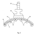
- the ceramic heating element shown in the drawings includes an elongate ceramic body 10 of arcuate cross-section with a concave front surface 12 and a convex rear surface 14.
- the body 10 has a plurality of substantially parallel, evenly spaced-apart, integral ribs 16 on its front concave surface 12, the ribs extending in the longitudinal direction of the body 10.
- the body 10, including the ribs 16, is glazed.
- a conventional heating wire in the form of a helical resistance wire 18, is embedded in the body 10. Respective lengths of the heating wire 18 extend along respective ones of the ribs 16.
- each rib 16 is substantially of semi-circular cross-section and each length of the heating wire 18 is located substantially at the centre of curvature of the respective rib 16.
- a ceramic boss 20 is cast integrally with the body 10 on its rear surface 14. Power leads 22 enter the body 10 through the boss 20 and are connected internally of the body 10 to supply current to the heating wire 18 in known manner.
- a wave spring and clip 24 permit mounting the heating element to a reflector system, also in known manner.
- the body 10 has embedded therein, between the heating wire 18 and the rear surface 14, a heat shield layer 28 of material which is both heat reflecting and heat insulating.
- the material 28 will substantially prevent heat loss by radiation through the rear surface 14 of the body 10 as it reflects the heat radiation back towards the front surface 12, and the material 28 will also substantially prevent transfer of heat by conduction to the rear surface 14 of the body 10.
- the heat shield layer 28 is preferably manufactured from a sheet of a high purity heat insulating material made of alumina silicate refractory fibres. After punching to produce the required shape for embedding in the body 10, the sheet is impregnated with an engobe material by drawing the sheet through a bath of a liquid engobe mixture.
- the bath consists of a mixture of 50% by volume of a ceramic glaze with reflective qualities and 50% by volume of a slip body.
- the glaze and slip body should have similar coefficients of thermal expansion as the body 10 to reduce the likelihood of failure due to stress cracks.
- the composite material gives the heat shield layer 28 its heat reflecting and heat insulating properties.
- the heating element further includes an in-built thermocouple sensor which consists of a pair of wires 30, 32 of dissimilar metal, e.g. nickel/nickel chrome, embedded in the body 10.
- an in-built thermocouple sensor which consists of a pair of wires 30, 32 of dissimilar metal, e.g. nickel/nickel chrome, embedded in the body 10.
- One portion of the heating wire 18 near the boss 20 is closely surrounded by a short length of quartz tube 34, and the thermocouple junction 36 is located in direct contact with the outside of the quartz tube 34.
- thermocouple By using a quartz tube any difficulties with regard electrical interference between the heating wire 18 and the thermocouple are avoided as quartz is a dielectric material. Also by using quartz, which is transparent to all emitted radiation, the thermocouple can follow rapidly and accurately the temperature change of the heating wire. By locating the thermocouple junction in contact with the quartz tube, which is of known diameter, the distance between the thermocouple and the heating wire is constant for all elements. This will in turn maintain a consistency in the thermocouple readings of different ceramic heating elements.
- thermocouple wires 30, 32 exit the body 10 through the boss 20, substantially parallel to the power leads 22 (Fig. 3).
- an insulating ceramic tube 38 is placed around the thermocouple wires within the boss.
- the power leads 22 and the thermocouple wires 30, 32 are positioned within a specialised insulating ceramic clay 40, which has a greater dielectric strength to ensure no induced or leakage current will interfere with the performance of the ungrounded thermocouple junction.
- the ceramic clay 40 comprises a low thermal response, matched engobe material (mixture of matched slip and glaze having similar coefficients of expansion). This is important where controllers may not have optical decoupling on the thermocouple card.
- the combination of these two features, tube 38 and clay 40, both of which are dielectric materials, substantially eliminates the problem of electrical interference in the boss.
- a ceramic heating element has been manufactured according to the principles described above to provide a uniform radiation output with a mass temperature range of 300 degrees centigrade to 750 degrees centigrade producing a wave length range of 6-3 microns.
Landscapes
- Chemical & Material Sciences (AREA)
- Engineering & Computer Science (AREA)
- Ceramic Engineering (AREA)
- Inorganic Chemistry (AREA)
- Resistance Heating (AREA)
Applications Claiming Priority (2)
| Application Number | Priority Date | Filing Date | Title |
|---|---|---|---|
| IE960875 | 1996-12-11 | ||
| IE960875 | 1996-12-11 |
Publications (3)
| Publication Number | Publication Date |
|---|---|
| EP0848574A2 true EP0848574A2 (de) | 1998-06-17 |
| EP0848574A3 EP0848574A3 (de) | 1998-12-16 |
| EP0848574B1 EP0848574B1 (de) | 2003-04-02 |
Family
ID=11041324
Family Applications (1)
| Application Number | Title | Priority Date | Filing Date |
|---|---|---|---|
| EP97650056A Expired - Lifetime EP0848574B1 (de) | 1996-12-11 | 1997-12-11 | Keramisches Heizelement |
Country Status (3)
| Country | Link |
|---|---|
| US (1) | US6075230A (de) |
| EP (1) | EP0848574B1 (de) |
| DE (1) | DE69720387D1 (de) |
Families Citing this family (7)
| Publication number | Priority date | Publication date | Assignee | Title |
|---|---|---|---|---|
| US6294769B1 (en) * | 1999-05-12 | 2001-09-25 | Mccarter David | Infrared food warming device |
| US7229547B2 (en) * | 2004-01-29 | 2007-06-12 | Oil-Tech, Inc. | Retort heating systems and methods of use |
| US7264694B2 (en) * | 2004-01-29 | 2007-09-04 | Oil-Tech, Inc. | Retort heating apparatus and methods |
| US7202447B2 (en) * | 2004-04-02 | 2007-04-10 | Kingdon Charles J | Conveyor type oven |
| WO2010011003A1 (en) * | 2008-07-21 | 2010-01-28 | Lg Electronics Inc. | A steam head for cleanner |
| US11457513B2 (en) | 2017-04-13 | 2022-09-27 | Bradford White Corporation | Ceramic heating element |
| CN114641105B (zh) * | 2022-03-30 | 2023-04-28 | 西安交通大学 | 一种基于双温度传感器的轴向非均匀间接电加热棒 |
Citations (4)
| Publication number | Priority date | Publication date | Assignee | Title |
|---|---|---|---|---|
| DE2618830A1 (de) * | 1976-04-29 | 1977-11-10 | Steinmetz Manfried | Infrarotstrahler, insbesondere aus keramik |
| GB2050130A (en) * | 1979-05-17 | 1980-12-31 | Steinmetz M | Infrared radiation apparatus |
| EP0211491A1 (de) * | 1985-08-06 | 1987-02-25 | Ngk Insulators, Ltd. | Infrarotheizkörper |
| JPH0495832A (ja) * | 1990-08-14 | 1992-03-27 | Ngk Insulators Ltd | 加熱装置およびその製造方法 |
Family Cites Families (4)
| Publication number | Priority date | Publication date | Assignee | Title |
|---|---|---|---|---|
| CH551125A (de) * | 1972-02-23 | 1974-06-28 | Steinmetz M Elstein Werk Kg | Infrarot-strahlungsanlage. |
| GB1581127A (en) * | 1975-09-27 | 1980-12-10 | Vulcan Refractories Ltd | Electrical heating devices |
| DE4201944C2 (de) * | 1991-01-24 | 2003-04-24 | Asahi Glass Co Ltd | Flüssigkeitsheizeinrichtung |
| DE4319019C2 (de) * | 1993-06-08 | 1996-01-25 | Elstein Werk M Steinmetz Kg | Infrarotstrahler aus Keramik für leistungsregelbare Erwärmungsanlagen |
-
1997
- 1997-12-11 US US08/988,904 patent/US6075230A/en not_active Expired - Lifetime
- 1997-12-11 DE DE69720387T patent/DE69720387D1/de not_active Expired - Lifetime
- 1997-12-11 EP EP97650056A patent/EP0848574B1/de not_active Expired - Lifetime
Patent Citations (4)
| Publication number | Priority date | Publication date | Assignee | Title |
|---|---|---|---|---|
| DE2618830A1 (de) * | 1976-04-29 | 1977-11-10 | Steinmetz Manfried | Infrarotstrahler, insbesondere aus keramik |
| GB2050130A (en) * | 1979-05-17 | 1980-12-31 | Steinmetz M | Infrared radiation apparatus |
| EP0211491A1 (de) * | 1985-08-06 | 1987-02-25 | Ngk Insulators, Ltd. | Infrarotheizkörper |
| JPH0495832A (ja) * | 1990-08-14 | 1992-03-27 | Ngk Insulators Ltd | 加熱装置およびその製造方法 |
Non-Patent Citations (1)
| Title |
|---|
| PATENT ABSTRACTS OF JAPAN vol. 016, no. 323 (P-1386), 15 July 1992 & JP 04 095832 A (NGK INSULATORS LTD), 27 March 1992 * |
Also Published As
| Publication number | Publication date |
|---|---|
| IE970879A1 (en) | 1998-06-17 |
| DE69720387D1 (de) | 2003-05-08 |
| EP0848574B1 (de) | 2003-04-02 |
| US6075230A (en) | 2000-06-13 |
| EP0848574A3 (de) | 1998-12-16 |
Similar Documents
| Publication | Publication Date | Title |
|---|---|---|
| US5296686A (en) | Heating element | |
| US4296311A (en) | Electric hot plate | |
| US6654549B1 (en) | Infrared light bulb, heating device, production method for infrared light bulb | |
| KR100914814B1 (ko) | 발열 유닛 및 가열 장치 | |
| EP0848574B1 (de) | Keramisches Heizelement | |
| US7915567B2 (en) | Heated resistance especially for heating a solid part such as a temperature probe and/or a pressure probe | |
| GB1593903A (en) | Electrical resistance coil heaters | |
| IE83450B1 (en) | Ceramic heating element | |
| JP3351573B2 (ja) | セラミック発熱体 | |
| CA1230634A (en) | Process for uniting sleeve members by brazing | |
| JP3128325B2 (ja) | 光ファイバ加工用小型電気炉 | |
| CN211481494U (zh) | 陶瓷纤维加热装置 | |
| JP4741929B2 (ja) | 赤外線電球及び加熱装置 | |
| JP4340677B2 (ja) | 発熱ユニット及び加熱装置 | |
| GB2074828A (en) | Electric heater | |
| US4042901A (en) | Temperature sensing resistance probe and method of making a resistance element therefor | |
| JPH07217886A (ja) | 自己制御型セラミックグロープラグ | |
| JP3954985B2 (ja) | 電気炉 | |
| SU758572A1 (ru) | Электронагреватель дл жидкости | |
| JPH0133734B2 (de) | ||
| GB2335834A (en) | Concave profile for element support material | |
| WO2020111196A1 (ja) | ヒータ | |
| JP4590053B2 (ja) | 取付部材付き金属被覆面状発熱体 | |
| JPS6014144Y2 (ja) | デイ−ゼルエンジン用グロ−プラグ | |
| KR200263203Y1 (ko) | 원적외선 방사형 전기히터 |
Legal Events
| Date | Code | Title | Description |
|---|---|---|---|
| PUAI | Public reference made under article 153(3) epc to a published international application that has entered the european phase |
Free format text: ORIGINAL CODE: 0009012 |
|
| AK | Designated contracting states |
Kind code of ref document: A2 Designated state(s): DE ES FR GB IT |
|
| AX | Request for extension of the european patent |
Free format text: AL;LT;LV;MK;RO;SI |
|
| PUAL | Search report despatched |
Free format text: ORIGINAL CODE: 0009013 |
|
| AK | Designated contracting states |
Kind code of ref document: A3 Designated state(s): AT BE CH DE DK ES FI FR GB GR IE IT LI LU MC NL PT SE |
|
| AX | Request for extension of the european patent |
Free format text: AL;LT;LV;MK;RO;SI |
|
| 17P | Request for examination filed |
Effective date: 19990616 |
|
| AKX | Designation fees paid |
Free format text: DE ES FR GB IT |
|
| 17Q | First examination report despatched |
Effective date: 20011029 |
|
| GRAH | Despatch of communication of intention to grant a patent |
Free format text: ORIGINAL CODE: EPIDOS IGRA |
|
| GRAH | Despatch of communication of intention to grant a patent |
Free format text: ORIGINAL CODE: EPIDOS IGRA |
|
| GRAA | (expected) grant |
Free format text: ORIGINAL CODE: 0009210 |
|
| AK | Designated contracting states |
Designated state(s): DE ES FR GB IT |
|
| PG25 | Lapsed in a contracting state [announced via postgrant information from national office to epo] |
Ref country code: IT Free format text: LAPSE BECAUSE OF FAILURE TO SUBMIT A TRANSLATION OF THE DESCRIPTION OR TO PAY THE FEE WITHIN THE PRE;WARNING: LAPSES OF ITALIAN PATENTS WITH EFFECTIVE DATE BEFORE 2007 MAY HAVE OCCURRED AT ANY TIME BEFORE 2007. THE CORRECT EFFECTIVE DATE MAY BE DIFFERENT FROM THE ONE RECORDED.SCRIBED TIME-LIMIT Effective date: 20030402 Ref country code: FR Free format text: LAPSE BECAUSE OF FAILURE TO SUBMIT A TRANSLATION OF THE DESCRIPTION OR TO PAY THE FEE WITHIN THE PRESCRIBED TIME-LIMIT Effective date: 20030402 |
|
| REG | Reference to a national code |
Ref country code: GB Ref legal event code: FG4D |
|
| REF | Corresponds to: |
Ref document number: 69720387 Country of ref document: DE Date of ref document: 20030508 Kind code of ref document: P |
|
| PG25 | Lapsed in a contracting state [announced via postgrant information from national office to epo] |
Ref country code: DE Free format text: LAPSE BECAUSE OF FAILURE TO SUBMIT A TRANSLATION OF THE DESCRIPTION OR TO PAY THE FEE WITHIN THE PRESCRIBED TIME-LIMIT Effective date: 20030703 |
|
| PG25 | Lapsed in a contracting state [announced via postgrant information from national office to epo] |
Ref country code: ES Free format text: LAPSE BECAUSE OF FAILURE TO SUBMIT A TRANSLATION OF THE DESCRIPTION OR TO PAY THE FEE WITHIN THE PRESCRIBED TIME-LIMIT Effective date: 20031030 |
|
| PG25 | Lapsed in a contracting state [announced via postgrant information from national office to epo] |
Ref country code: GB Free format text: LAPSE BECAUSE OF NON-PAYMENT OF DUE FEES Effective date: 20031211 |
|
| PLBE | No opposition filed within time limit |
Free format text: ORIGINAL CODE: 0009261 |
|
| STAA | Information on the status of an ep patent application or granted ep patent |
Free format text: STATUS: NO OPPOSITION FILED WITHIN TIME LIMIT |
|
| EN | Fr: translation not filed | ||
| 26N | No opposition filed |
Effective date: 20040105 |
|
| GBPC | Gb: european patent ceased through non-payment of renewal fee |
Effective date: 20031211 |