EP0845427B1 - Apparatus for transporting thin glass sheets - Google Patents
Apparatus for transporting thin glass sheets Download PDFInfo
- Publication number
- EP0845427B1 EP0845427B1 EP97120328A EP97120328A EP0845427B1 EP 0845427 B1 EP0845427 B1 EP 0845427B1 EP 97120328 A EP97120328 A EP 97120328A EP 97120328 A EP97120328 A EP 97120328A EP 0845427 B1 EP0845427 B1 EP 0845427B1
- Authority
- EP
- European Patent Office
- Prior art keywords
- glass
- plates
- pane
- panes
- plate
- Prior art date
- Legal status (The legal status is an assumption and is not a legal conclusion. Google has not performed a legal analysis and makes no representation as to the accuracy of the status listed.)
- Expired - Lifetime
Links
Images

Classifications
-
- B—PERFORMING OPERATIONS; TRANSPORTING
- B65—CONVEYING; PACKING; STORING; HANDLING THIN OR FILAMENTARY MATERIAL
- B65G—TRANSPORT OR STORAGE DEVICES, e.g. CONVEYORS FOR LOADING OR TIPPING, SHOP CONVEYOR SYSTEMS OR PNEUMATIC TUBE CONVEYORS
- B65G49/00—Conveying systems characterised by their application for specified purposes not otherwise provided for
- B65G49/05—Conveying systems characterised by their application for specified purposes not otherwise provided for for fragile or damageable materials or articles
- B65G49/06—Conveying systems characterised by their application for specified purposes not otherwise provided for for fragile or damageable materials or articles for fragile sheets, e.g. glass
- B65G49/063—Transporting devices for sheet glass
- B65G49/064—Transporting devices for sheet glass in a horizontal position
- B65G49/065—Transporting devices for sheet glass in a horizontal position supported partially or completely on fluid cushions, e.g. a gas cushion
-
- B—PERFORMING OPERATIONS; TRANSPORTING
- B65—CONVEYING; PACKING; STORING; HANDLING THIN OR FILAMENTARY MATERIAL
- B65G—TRANSPORT OR STORAGE DEVICES, e.g. CONVEYORS FOR LOADING OR TIPPING, SHOP CONVEYOR SYSTEMS OR PNEUMATIC TUBE CONVEYORS
- B65G2249/00—Aspects relating to conveying systems for the manufacture of fragile sheets
- B65G2249/04—Arrangements of vacuum systems or suction cups
-
- Y—GENERAL TAGGING OF NEW TECHNOLOGICAL DEVELOPMENTS; GENERAL TAGGING OF CROSS-SECTIONAL TECHNOLOGIES SPANNING OVER SEVERAL SECTIONS OF THE IPC; TECHNICAL SUBJECTS COVERED BY FORMER USPC CROSS-REFERENCE ART COLLECTIONS [XRACs] AND DIGESTS
- Y10—TECHNICAL SUBJECTS COVERED BY FORMER USPC
- Y10T—TECHNICAL SUBJECTS COVERED BY FORMER US CLASSIFICATION
- Y10T83/00—Cutting
- Y10T83/202—With product handling means
- Y10T83/2033—Including means to form or hold pile of product pieces
- Y10T83/2037—In stacked or packed relation
Definitions
- the invention relates to a method for handling thin Glass panes or similar flat workpieces and products by means of pneumatic forces and a device for carrying out the Process.
- Thin flat glass is widely used to manufacture displays used. Scratches, inclusions, deposits, etc. larger than about 10 ⁇ m considered an error because they are on the finished display cause local image disturbances that are intolerable. To have to therefore extensive control measures are envisaged to identify and sort out unusable products.
- An indispensable manufacturing step is formatting the for economic reasons in large panels or as a broad, wound strip of raw glass, i.e. the cutting on the desired display size including edge and Corner processing, where necessary, a final cleaning must connect.
- EP 0 336 332 B1 describes a device for gripping, opening and closing Stacking as well as conveying glass panels known, also from another context known, working with negative pressure Suction pads are used.
- suction pads can below a minimum glass thickness cannot be used because the thin Bend the glass pane in the area of the suction cups, in the worst case Case would break too.
- the bracket is by means of Suction pads for very thin glass panes for spreading like Cutting, grinding and / or polishing are not suitable because the Clamping is not even, or not in the machining area can be maintained evenly. Otherwise prevent Suction pads also do not contaminate the glass surfaces when Transport and processing.
- the invention is based, a method and a task Device for handling thin glass panes in To propose processing plants, especially in cutting plantations, which allow both the existing raw gas formats and the To hold and transport finished formats so that the surfaces not be damaged that deposits of dirt particles, Cutting chips or the like can be avoided and that Glass breakage is excluded as far as possible. It must be taken into account that the waiving of polishing from technical or economic reasons, the pursuit of bigger and bigger ones Display formats and the increasingly strict specifications an extremely gentle one with regard to the size and frequency of errors Require handling of the glass.
- a method according to claim 1 proposed.
- this process in a first Operation of both plates of the device with overpressure be applied so that the glass pane between the plates is kept non-contact, or it can be in a second Operating mode one plate with overpressure and the other plate with Vacuum can be applied, so that the glass pane on a Plate pressed and held by it.
- the first Operation is on both sides of the between the plates located glass pane a preferably the same size, on the edge maintain escaping gas flow which ensures that existing dust or the like is discharged to the outside and that nothing can penetrate from outside.
- that the glass pane does not touch either the top or the bottom plate and therefore can be moved horizontally between the plates, without the risk of scratching the glass surface.
- the gas stream generated preferably emerges in pairs opposite openings.
- the second mode of operation in which the glass pane on one of the plates is held either serves to hold the glass when fixed Plate too edit or together with the plate in another position relocate, for example from the processing to a filing or Transport stack position.
- the glass pane lies on the plate on the vacuum side so that no contaminants can penetrate here if the The surface of the plate is sufficiently flat and smooth, or if there is one on the edge suitable seal is arranged between the plate and glass.
- the first mode of operation ensures that the Glass surface act everywhere about the same pneumatic forces, whereby bulging of the thin glass sheet from the plane is avoided. It can also have a certain smoothing effect on the thin glass pane can be achieved.
- a smoothing effect that smoothes out of paper by hand movement can also be achieved when the gas passage openings in areas from the center of the plates progressively subjected to positive or negative pressure on the outside.
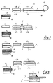
- the device shown in greatly simplified form in FIG. 1 comprises an upper one Plate 1 and a lower plate 2, a thin glass sheet 3 between them Include without contact. This is achieved when the two are in pairs opposite gas passage openings 4 in both plates 1, 2 with a gas delivery device for generating positive pressure are connected.
- FIG. 2 schematically shows the position of the glass pane 3 when the upper plate 1 with negative pressure and the lower plate 2 is pressurized.
- figure 3 shows the position of the glass pane 3 when pressure is applied in reverse.
- the glass sheet 3 in the area outside the upper plate are processed, the lower plate as an abutment for Serves machining forces or together with the upper one Plate can be moved vertically and horizontally to frame it automated manufacturing process from the position shown in the to move to the next position.
- the glass pane also processed in the position shown in Figure 3 and together with the lower Plate 2 are transported. In all cases he takes care of the spaced plate 1, 2 exiting gas flow to ensure that the free Glass surface not caused by dust or particles from processing can be contaminated. The adjacent glass surface is anyway protected.
- the plate 1 according to FIG suitable seal 5 provided with a soft elastic tongue supported on the thin glass pane and thus the penetration of foreign particles prevents and also improves negative pressure maintenance.
- a such a seal can also be provided on both plates 1, 2 if it is ensured that the thin glass pane does not have any bending forces is subjected.
- FIG. 5 shows a possible sequence of work steps during processing of thin glass, in which the device according to the invention is advantageous can be used.
- the entire facility comprises a total of three upper and two lower plates (1a - 1c, 2a, 2b), one behind the other in the working direction are arranged and a straight horizontal working path for the glass pane 3 or 3 'for glass sections separated therefrom.
- the illustrated Case is assumed from a wound raw glass bale 10, the unwound end via a feed device 6 into a processing station is transported.
- the feed station 6 comprises an upper plate 1a and one lower plate 2a, both with opposite pairs Gas passage openings are equipped and as described, with over or Vacuum can be applied.
- the lower plate 2a is essential longer than the top plate 1a, with the one protruding to the right Part either none or separately actable Gas passage openings are provided.
- the plates 1a and 2a can be fixed because they are non-contact, floating Positioning during glass transport have no function.
- the plates 1b and 2b of the processing station 7 are essentially the same large and provided in the same way with gas passage openings, wherein slight deviations of the area, as shown in the figures 1 to 4 can be seen, are not shown here. However, it should be noted that at least the plate 1b of the processing station 7 generally somewhat is narrower than the glass ribbon to be processed, making it double-sided Edge trimming is easily possible.
- the glass sheet 3 or the raw glass band is not through shown, attacking edge means of transport in the "floating state" so subtracted far from right to left from the raw glass bale 10 that a front cutting edge in the area of the left end of the processing station 7 lies.
- the plate 1c is in its rest position above the Stacking device 8 and the already finished glass sections 3 '.
- Figure 5b are the upper plates 1a and 1b with overpressure and the lower plates 2a and 2b applied with negative pressure.
- the glass pane 3 lies on the lower plates 2a, 2b and is thus fixed in the processing position.
- she can now be processed by means of a cutting device 9, i.e. it a glass section 3 'can be separated from the raw glass ribbon.
- Everyone can suitable cutting devices are used. Will the Glass pane is not completely cut through, but only weakened, In the case of thin glass in particular, changing the Pressurization in the feed device 6 or in the Processing station 7 to break the remaining cross section. It can of course also use known glass breaking devices become.
- Figure 5c it is shown how the glass section 3 'by means of the horizontal movable plate 2b brought into a position opposite the upper plate 1c and was sucked in by it. After returning the plate 2b in its Starting position, the plate 1c according to Figure 5b for storing the Move glass section 3 'vertically downwards on the stacking device 8 become. At the same time, the raw glass ribbon can be fed into the feed device 6 Hover position raised and then into the Processing station 7 are transported. In this way it is rational Clock sequence realizable.
- the work steps shown in Figure 5 can of course also with more and different moving plates can be performed.
- a depositing movement transversely to the transport device of the raw glass band be provided.
- the idea of the invention can also advantageously be applied if thin glass in individual sections or as a tape over a longer one Route must be transported.
- pressure on both sides can be a non-contact Transport can be realized, of course attacking on the edge Conveyor belts or the like must be provided.
- the advantages according to the invention can be used in all cases: optional non-contact and bending-free guidance and mounting, holding the glass pane on a plate and keeping the glass surfaces clean permanent gas flow or close contact with a plate during the overall handling.
Description
Die Erfindung betrifft ein Verfahren zur Handhabung dünner Glasscheiben oder ähnlicher flächiger Werkstücke und Produkte mittels pneumatischer Kräfte sowie eine Vorrichtung zur Durchführung des Verfahrens.The invention relates to a method for handling thin Glass panes or similar flat workpieces and products by means of pneumatic forces and a device for carrying out the Process.
Dünnes Flachglas wird in großem Umfang zur Herstellung von Displays verwendet. Dabei werden Kratzer, Einschlüsse, Ablagerungen usw. größer etwa 10µm als Fehler angesehen, weil sie am fertigen Display lokale Bildstörungen verursachen, die nicht tolerierbar sind. Es müssen daher umfangreiche Kontrollmaßnahmen vorgesehen werden, um unbrauchbare Erzeugnisse zu erkennen und auszusortieren.Thin flat glass is widely used to manufacture displays used. Scratches, inclusions, deposits, etc. larger than about 10µm considered an error because they are on the finished display cause local image disturbances that are intolerable. To have to therefore extensive control measures are envisaged to identify and sort out unusable products.
Da außerdem hohe Anforderungen an die Ebenheit und Parallelität des für Displays eingesetzten Flachglases bestehen, ist im Herstellungsprozess üblicherweise ein Polieren der Oberflächen vorgesehen. Damit lassen sich zwar viele vorhandene Fehler beseitigen, die Herstellung wird aber auch erheblich verteuert. Man ist daher sehr darum bemüht, den Poliervorgang einzusparen.Since there are also high demands on the flatness and parallelism of the flat glass used for displays is in Manufacturing process usually polishing the surfaces intended. This allows many existing errors eliminate, but the production is also considerably more expensive. One is therefore make every effort to save the polishing process.
Bei neueren Herstellungsverfahren für Flachglas können die Anforderungen an die Ebenheit und Parallelität der Glasoberflächen in zunehmendem Maße am gezogenen oder gefloateten Rohglas eingehalten werden, so dass man wegen der Kostenvorteile auf das Polieren verzichten kann. Damit entfällt aber auch die Möglichkeit zur Fehlerbeseitigung. Andererseits ist ein Polieren von Flachglas mit einer Dicke im Bereich von 30 bis 300µm derzeit noch nicht oder nur mit unvertretbar hohem Aufwand bei Glasscheiben für kleine Disptayformate möglich. Projektiert werden heute u.a. dagegen Formate bis zu 650 x 1000 mm bei einer Scheibendicke im Bereich von 50µm. Außerdem werden die Spezifikationen hinsichtlich Fehtergröße und Anzahl der Fehler pro Flächeneinheit bei den neueren Display-Ausführungen, wie Field Emission Display (FED), Plasma Display Panel (PDP), Plasma Addressed Liquid Cristal (PALC), THin Film Transistor (TFT) oder Super Twisted Nemetic (STN) immer strenger, so dass die Glashersteller zu immer größeren Anstrengungen gezwungen werden, um ein technisch und wirtschaftlich akzeptables Produkt anbieten zu können.With newer manufacturing processes for flat glass, the Requirements for the flatness and parallelism of the glass surfaces in increasingly on the drawn or floated raw glass be adhered to so that due to the cost advantages on the Can do without polishing. However, this also eliminates the possibility of Troubleshooting. On the other hand, polishing flat glass with a Thickness in the range of 30 to 300 µm is currently not or only with unacceptably high effort with glass panes for small Disptay formats possible. Today, among other things, on the other hand Formats up to 650 x 1000 mm with a pane thickness in the range of 50 .mu.m. In addition, the specifications regarding defect size and number of errors per unit area in the newer display versions, like Field Emission Display (FED), Plasma Display Panel (PDP), Plasma Addressed Liquid Cristal (PALC), THin Film Transistor (TFT) or Super Twisted Nemetic (STN) are becoming stricter, so the Glassmakers are forced to make ever greater efforts to offer a technically and economically acceptable product can.
Ein unverzichtbarer Herstellungsschritt ist das Formatieren des aus wirtschaftlichen Gründen in großen Tafeln oder auch als breites, aufgewickeltes Band erzeugten Rohglases, d.h. das Schneiden auf die gewünschte Displaygröße einschließlich Kanten- und Eckenbearbeitung, woran sich gegebenenfalls noch eine Endreinigung anschließen muss.An indispensable manufacturing step is formatting the for economic reasons in large panels or as a broad, wound strip of raw glass, i.e. the cutting on the desired display size including edge and Corner processing, where necessary, a final cleaning must connect.
Aus der DE 17 56 070 B2 ist zwar schon eine Vorrichtung zum Transportieren von Glas in Form einer Scheibe oder eines Bandes bekannt geworden, bei der das Glas auf einem Gaskissen beanstandet zu einer Unterkonstruktion liegt und berührungsfrei horizontal relativ zur Unterkonstruktion bewegt werden kann. Die Unterkonstruktion ist mit nebeneinander liegenden Schlitzen für den Gasdurchtritt ausgestattet, die jedoch wechselnd als Austritts- und Absaugschlitze ausgebildet und mit entsprechenden Über- und Unterdruckquellen verbunden sind. Dadurch wird an der Glasoberfläche ein Wechselfeld einander entgegengerichteter Kräfte erzeugt, denen dünne Glasscheiben nicht standhalten würden. Außerdem wird bestenfalls nur eine der beiden Glasoberflächen gegen Verschmutzung geschützt.From DE 17 56 070 B2 there is already a device for Transporting glass in the form of a disc or a ribbon became known in which the glass on a gas cushion complained to a substructure and non-contact horizontally relative to Substructure can be moved. The substructure is with side-by-side slots for gas passage, which, however, are alternately designed as outlet and suction slots and are connected to corresponding sources of positive and negative pressure. This creates an alternating field on the glass surface opposing forces generated, which thin glass panes do not would withstand. In addition, at best, only one of the two Glass surfaces protected against dirt.
Ferner ist aus der EP 0 336 332 B1 eine Vorrichtung zur Greifen, Aufund Abstapeln sowie Fördern von Glastafeln bekannt, bei der auch aus anderem Zusammenhang bekannte, mit Unterdruck arbeitende Sauggreifer verwendet werden. Derartige Sauggreifer können unterhalb einer Mindestglasdicke nicht verwendet werden, weil sich die dünne Glasscheibe im Bereich der Sauggreifer durchbiegen, im ungünstigsten Fall auch brechen würde. Außerdem ist die Halterung mittels Sauggreifern bei sehr dünnen Glasscheiben für eine Beareitung wie Schneiden, Schleifen und/oder Polieren nicht geeignet, weil die Einspannung nicht gleichmäßig ist, bzw. im Bearbeitungsbereich nicht gleichmäßig aufrechterhalten werden kann. Im übrigen verhindern die Sauggreifer auch nicht die Verschmutzung der Glasoberflächen beim Transport und bei der Bearbeitung.Furthermore, EP 0 336 332 B1 describes a device for gripping, opening and closing Stacking as well as conveying glass panels known, also from another context known, working with negative pressure Suction pads are used. Such suction pads can below a minimum glass thickness cannot be used because the thin Bend the glass pane in the area of the suction cups, in the worst case Case would break too. In addition, the bracket is by means of Suction pads for very thin glass panes for spreading like Cutting, grinding and / or polishing are not suitable because the Clamping is not even, or not in the machining area can be maintained evenly. Otherwise prevent Suction pads also do not contaminate the glass surfaces when Transport and processing.
Bei dem aus der US-A-3,355,275 bekannten, berührungsfreien Transport eines aus einer Glasschmelze abgezogenen Glasbandes wird eine Vorrichtung verwendet, bei der unterhalb und oberhalb des Transportraumes für das Glas eine Mehrzahl von Modulen für die Zuund Abfuhr von Kühlluft angeordnet ist, die unterhalb des Glasbandes außerdem ein tragendes Gaspolster bildet. Auch diese Vorrichtung ist für die Handhabung dünner Glasscheiben nicht geeignet, weil durch die in Transportrichtung abwechselnd angeordneten Öffnungen für die Zuund Abfuhr von Kühlluft ein schädliches Wechselfeld pneumatischer Kräfte erzeugt wird. Das gleiche gilt für die aus der FR-A-20 24 397 bekannte Vorrichtung.In the contact-free known from US-A-3,355,275 Transport of a glass ribbon drawn from a glass melt a device is used in which below and above the Transport space for the glass a plurality of modules for the Zuund Removal of cooling air is arranged below the glass ribbon also forms a load-bearing gas cushion. This device is also not suitable for handling thin glass panes because of the Openings alternately arranged in the direction of transport for the feeders Removal of cooling air is a harmful alternating field pneumatic Forces is generated. The same applies to those from FR-A-20 24 397 known device.
Der Erfindung liegt die Aufgabe zugrunde, ein Verfahren und eine Vorrichtung zur Handhabung von dünnen Glasscheiben in Bearbeitungsanlagen, insbesondere in Schneidantagen vorzuschlagen, die es erlauben, sowohl die vorhandenen Rohgtasformate wie auch die Fertigformate so zu halten und zu transportieren, dass die Oberflächen nicht beschädigt werden, dass Ablagerungen von Schmutzpartikeln, Schneidsplittem oder dergleichen vermieden werden und dass Glasbruch möglichst ausgeschlossen ist. Dabei ist zu berücksichtigen, dass der Verzicht auf das Polieren aus technischen oder wirtschaftlichen Gründen das Streben zu immer größeren Displayformaten und die zunehmen strengeren Spezifikationen hinsichtlich Fehlergröße und Fehlerhäufigkeit eine äußerst schonende Handhabung des Glases erfordern.The invention is based, a method and a task Device for handling thin glass panes in To propose processing plants, especially in cutting plantations, which allow both the existing raw gas formats and the To hold and transport finished formats so that the surfaces not be damaged that deposits of dirt particles, Cutting chips or the like can be avoided and that Glass breakage is excluded as far as possible. It must be taken into account that the waiving of polishing from technical or economic reasons, the pursuit of bigger and bigger ones Display formats and the increasingly strict specifications an extremely gentle one with regard to the size and frequency of errors Require handling of the glass.
Zur Lösung dieser Aufgabe wird ein Verfahren gemäß Anspruch 1
vorgeschlagen. Bei diesem Verfahren können in einer ersten
Betriebsweise beide Platten der Vorrichtung mit Überdruck
beaufschlagt werden, so dass die Glasscheibe zwischen den Platten
berührungsfrei gehalten wird, oder aber es kann in einer zweiten
Betriebsweise eine Platte mit Überdruck und die andere Platte mit
Unterdruck beaufschlagt werden, so dass die Glasscheibe an eine
Platte angedrückt und von ihr festgehalten wird. In der ersten
Betriebsweise wird zu beiden Seiten der zwischen den Platten
befindlichen Glasscheibe ein vorzugsweise gleich großer, randseitig
austretender Gasstrom aufrechterhalten, der dafür sorgt, dass
vorhandener Staub oder dergleichen nach außen abgeführt wird und
dass von außen nichts eindringen kann. Gleichzeitig wird dafür gesorgt,
dass die Glasscheibe weder die obere noch die untere Platte berührt
und daher zwischen den Platten horizontal weiterbewegt werden kann,
ohne dass die Gefahr besteht, dass die Glasoberfläche verkratzt wird.
Vorzugsweise tritt der erzeugte Gasstrom aus paarweise
gegenüberliegenden Öffnungen aus.To achieve this object, a method according to
Dabei kann man den bekannten Setbststeuerungseffekt ausnutzen, der dadurch entsteht, dass eine vertikale Verlagerung der Glasscheibe, d.h. eine Annäherung an eine der Platten dazu führt, dass sich der Strömungsquerschnitt zwischen der Glasscheibe und der anderen Platte vergrößert, der pneumatische Druck bei unverändertem Gasdurchsatz auf dieser Seite abnimmt und Kräfte wirksam werden, die der vertikalen Verlagerung entgegenwirken. Die in einer Richtung senkrecht auf die Glasscheibe wirkende Erdbeschleunigung kann dabei durch marginal höheren Überdruck an der unteren Platte ohne weiteres regeltechnisch kompensiert werden, wenn eine genau mittige Lage der Glasscheibe zwischen den Platten erforderlich ist. You can take advantage of the well-known self-control effect, the This results in a vertical displacement of the glass pane, i.e. approaching one of the plates causes the Flow cross-section between the glass pane and the other The plate is enlarged, the pneumatic pressure remains unchanged Gas throughput decreases on this side and forces become effective counteract the vertical shift. The one way Gravitational acceleration acting perpendicularly on the glass pane can due to marginally higher overpressure on the lower plate be compensated for by the control system if the center of the Glass pane between the plates is required.
Die zweite Betriebsweise, bei der die Glasscheibe an einer der Platten festgehalten wird, dient entweder dazu, das Glas bei feststehender Platte zu bearbeiten oder aber zusammen mit der Platte in eine andere Position zu verlagern, beispielsweise aus der Bearbeitungs- in eine Ablage- oder Stapelposition zu transportieren.The second mode of operation, in which the glass pane on one of the plates is held either serves to hold the glass when fixed Plate too edit or together with the plate in another position relocate, for example from the processing to a filing or Transport stack position.
Solange sich die Glasscheibe zwischen den beiden Platten befindet, wird auf der Überdruckseite, wie zuvor dafür gesorgt, daß diese Glasoberfläche nicht verschmutzen kann. Auf der Unterdruckseite liegt die Glasscheibe an der Platte an, so daß auch hier keine Verunreinigungen eindringen können, wenn die Oberfläche der Platte ausreichend eben und glatt ist oder wem randseitig eine geeignete Dichtung zwischen Platte und Glasscheibe angeordnet ist.As long as the glass pane is between the two plates, is on the pressure side, as previously ensured that this glass surface is not can pollute. The glass pane lies on the plate on the vacuum side so that no contaminants can penetrate here if the The surface of the plate is sufficiently flat and smooth, or if there is one on the edge suitable seal is arranged between the plate and glass.
Mit der Anordnung paarweise gegenüberliegender Gasdurchtrittsöffnungen wird bei der ersten Betriebsweise dafür gesorgt, daß auf beiden Seiten der Glasfläche überall etwa die gleichen pneumatischen Kräfte wirken, wodurch ein Auswölben der dünnen Glasscheibe aus der Ebene vermieden wird. Außerdem kann so ein gewisser Glättungseffekt an der dünnen Glasscheibe erreicht werden.With the arrangement of gas passage openings opposite each other in pairs the first mode of operation ensures that the Glass surface act everywhere about the same pneumatic forces, whereby bulging of the thin glass sheet from the plane is avoided. It can also have a certain smoothing effect on the thin glass pane can be achieved.
In der zweiten Betriebsweise kann ein Glättungseffekt, der dem Glattstreichen von Papier mittels einer Handbewegung entspricht, auch erreicht werden, wenn die Gasdurchtrittsöffnungen bereichsweise vom Zentrum der Platten nach außen fortschreitend mit Über- oder Unterdruck beaufschlagt werden.In the second mode of operation, a smoothing effect that smoothes out of paper by hand movement can also be achieved when the gas passage openings in areas from the center of the plates progressively subjected to positive or negative pressure on the outside.
Vorteilhafte Ausgestaltungen und Abwandlungen des Erfindungsgedankens sind in den Ansprüchen 2 bis 20 beschrieben. Weitere Einzelheiten werden anhand der in den Figuren 1 bis 5 dargestellten Ausführungsbeispiele näher erläutert.
Figur 1- zeigt einen Vertikalschnitt durch eine Vorrichtung gemäß der Erfindung in schematischer Darstellung.
Figur 2- zeigt eine Seitenansicht der Vorrichtung nach
Anspruch 1. Figur 3- zeigt ebenfalls eine Seitenansicht der Vorrichtung nach
Anspruch 1. - Figur 4
- zeigt in vergrößerter Darstellung einen Schnitt durch den Randbereich einer Vorrichtung gemäß der Erfindung.
- Figur 5
- zeigt schematisch eine Abfolge von Arbeitsschritten unter Verwendung einer Vorrichtung gemäß der Erfindung.
- Figure 1
- shows a vertical section through a device according to the invention in a schematic representation.
- Figure 2
- shows a side view of the device according to
claim 1. - Figure 3
- also shows a side view of the device according to
claim 1. - Figure 4
- shows an enlarged view of a section through the edge region of a device according to the invention.
- Figure 5
- shows schematically a sequence of work steps using a device according to the invention.
Die in Figur 1 stark vereinfacht dargestellte Vorrichtung umfaßt eine obere
Platte 1 und eine untere Platte 2, die zwischen sich eine dünne Glasscheibe 3
berührungsfrei einschließen. Dies wird erreicht, wenn die paarweise einander
gegenüberliegenden Gasdurchtrittsöffnungen 4 bei beiden Platten 1, 2 mit
einer Gasfördereinrichtung zur Erzeugung von Überdruck verbunden sind. Die
oberhalb und unterhalb der dünnen Glasscheibe 3 aus den Platten 1, 2
austretenden paarweise gleichen Gasströme halten die dünne Glasscheibe 3
quasi in der Schwebe, wobei eine vertikale Verlagerung der Glasscheibe, wie
bereits erläutert, sofort entgegengesetzt gerichtete Kräfte erzeugt, so daß die
berührungsfreie Lage der Glasscheibe 3 zwischen den Platten 1, 2
selbstregelnd eingehalten wird.The device shown in greatly simplified form in FIG. 1 comprises an upper one
In dieser Lage kann die Glasscheibe 3 zwischen den Platten 1,
2 berührungsfrei gehalten und horizontal fixiert bzw. transportiert werden,
wobei übliche, nicht dargestellte Transportmittel an der randseitig vorstehenden
Glasscheibe 3 angreifen können.In this position, the
Figur 2 zeigt schematisch die Lage der Glasscheibe 3, wenn die obere Platte 1
mit Unterdruck und die untere Platte 2 mit Überdruck beaufschlagt wird. Figur
3 zeigt die Lage der Glasscheibe 3 bei umgekehrter Druckbeaufschlagung. In
der Lage gemäß Figur 2 kann die Glasscheibe 3 im Bereich außerhalb der
oberen Platte bearbeitet werden, wobei die untere Platte als Widerlager zur
Aufnahme von Bearbeitungskräften dient oder aber zusammen mit der oberen
Platte vertikal und horizontal bewegt werden, um sie im Rahmen eines
automatisierten Herstellungsprozesses aus der dargestellten Position in die
nächstfolgende Position zu verlagern. In gleicher Weise kann die Glasscheibe
auch in der Lage gemäß Figur 3 bearbeitet und zusammen mit der unteren
Platte 2 transportiert werden. In allen Fällen sorgt der aus der jeweils
beabstandeten Platte 1, 2 austretende Gasstrom dafür, daß die freie
Glasoberfläche nicht durch Staub oder bei der Bearbeitung anfallende Partikel
verunreinigt werden kann. Die anliegende Glasoberfläche ist insoweit ohnehin
geschützt.FIG. 2 schematically shows the position of the
Beim Übergang von der Druckbeaufschlagung gemäß Figur 1 auf eine
Druckbeaufschlagung gemäß Figur 2 oder 3, tritt kurzzeitig ein von außen
nach innen gerichteter Gasstrom auf, der Verschmutzungen eintragen könnte.
Um dies zu vermeiden, ist die Platte 1 gemäß Figur 4 randseitig mit einer
geeigneten Dichtung 5 versehen, die sich mit einer weichen elastischen Zunge
auf der dünnen Glasscheibe abstützt und so das Eindringen von Fremdpartikeln
verhindert und darüber hinaus auch die Unterdruckhaltung verbessert. Eine
derartige Dichtung kann auch an beiden Platten 1, 2 vorgesehen werden, wenn
gewährleistet ist, daß die dünne Glasscheibe dadurch keinen Biegekräften
unterworfen wird.During the transition from the pressurization according to FIG. 1 to one
Pressurization according to Figure 2 or 3 occurs briefly from the outside
inward gas flow that could enter contaminants.
In order to avoid this, the
Figur 5 zeigt eine mögliche Abfolge von Arbeitsschritten bei der Bearbeitung
von dünnem Glas, bei der die erfindungsgemäße Vorrichtung vorteilhaft
einsetzbar ist. Die gesamte Einrichtung umfaßt insgesamt drei obere und zwei
untere Platten (1a - 1c, 2a, 2b), die in Arbeitsrichtung hintereinander
angeordnet sind und einen geraden horizontalen Arbeitsweg für die Glasscheibe
3 bzw. für davon abgetrennte Glasabschnitte 3' definieren. Im dargestellten
Fall wird von einem aufgewickelten Rohglasballen 10 ausgegangen, dessen
abgewickeltes Ende über eine Zuführeinrichtung 6 in eine Bearbeitungsstation
transportiert ist. Die Zuführstation 6 umfaßt eine obere Platte 1a und eine
untere Platte 2a, die beide mit paarweise gegenüberliegenden
Gasdurchtrittsöffnungen ausgestattet sind und wie beschrieben, mit Über- oder
Unterdruck beaufschlagt werden können. Die untere Platte 2a ist wesentlich
länger ausgeführt als die obere Platte 1a, wobei im nach rechts überstehenden
Teil entweder keine oder aber getrennt beaufschlagbare
Gasdurchtrittsöffnungen vorgesehen sind. Die Platten 1a und 2a können
ortsfest angeordnet sein, weil sie außer der berührungsfreien, schwebenden
Lagehaltung beim Glastransport keine Funktion haben.FIG. 5 shows a possible sequence of work steps during processing
of thin glass, in which the device according to the invention is advantageous
can be used. The entire facility comprises a total of three upper and two
lower plates (1a - 1c, 2a, 2b), one behind the other in the working direction
are arranged and a straight horizontal working path for the
Die Platten 1b und 2b der Bearbeitungsstation 7 sind im wesentlichen gleich
groß und in gleicher Weise mit Gasdurchtrittsöffnungen versehen, wobei
geringfügige Abweichungen der flächigen Erstreckung, wie sie aus den Figuren
1 bis 4 ersichtlich sind, hier nicht dargestellt sind. Es sei jedoch erwähnt, daß
zumindest die Platte 1b der Bearbeitungsstation 7 im allgemeinen etwas
schmaler ist als das zu bearbeitende Glasband, damit eine beidseitige
Randbeschneidung ohne weiteres möglich ist.The plates 1b and 2b of the
In Figur 5a ist die Glasscheibe 3 bzw. das Rohglasband durch nicht
dargestellte, randseitig angreifende Transportmittel im "Schwebezustand" so
weit von rechts nach links von dem Rohglasballen 10 abgezogen, daß eine
vordere Schnittkante im Bereich des linken Endes der Bearbeitungsstation 7
liegt. Die Platte 1c befindet sich in ihrer Ruheposition oberhalb der
Stapeleinrichtung 8 und den bereits fertigen Glasabschnitten 3'. In Figur 5b
sind die oberen Platten 1a und 1b mit Überdruck und die unteren Platten 2a
und 2b mit Unterdruck beaufschlagt. Dabei liegt die Glasscheibe 3 an den
unteren Platten 2a, 2b an und ist damit in der Bearbeitungslage fixiert. Sie
kann nunmehr mittels einer Schneideinrichtung 9 bearbeitet werden, d.h. es
kann ein Glasabschnitt 3' vom Rohglasband abgetrennt werden. Es können alle
geeigneten Schneidvorrichtungen zur Anwendung kommen. Wird die
Glasscheibe dabei nicht gänzlich durchgetrennt, sondern nur geschwächt,
genügt insbesondere bei dünnem Glas schon die Änderung der
Druckbeaufschlagung in der Zuführeinrichtung 6 oder in der
Bearbeitungsstation 7, um den verbleibenden Restquerschnitt zu brechen. Es
können aber selbstverständlich auch bekannte Glasbrecheinrichtungen benutzt
werden.In Figure 5a, the
Auch an dieser Stelle sei erwähnt, daß das Rohglasband an den Längskanten
der Bearbeitungsstation 7 übersteht und in ähnlicher Weise bearbeitet werden
kann. Selbstverständlich sind hier und an den quer zur Bandrichtung
verlaufenden Schneidkanten auch gegebenenfalls erforderliche Kanten- und
Eckenbearbeitungen durch Schleifen ausführbar.At this point it should also be mentioned that the raw glass strip on the longitudinal edges
the
In Figur 5c ist gezeigt, wie der Glasabschnitt 3' mittels der horizontal
beweglichen Platte 2b in eine Position gegenüber der oberen Platte 1c gebracht
und von dieser angesaugt wurde. Nach dem Rückfahren der Platte 2b in ihre
Ausgangsposition kann die Platte 1c gemäß Figur 5b zur Ablage des
Glasabschnitts 3' auf der Stapeleinrichtung 8 vertikal nach unten verfahren
werden. Gleichzeitig kann das Rohglasband in der Zuführeinrichtung 6 in die
Schwebeposition angehoben und danach berührungsfrei in die
Bearbeitunsstation 7 transportiert werden. Auf diese Weise ist eine rationelle
Taktfolge realisierbar.In Figure 5c it is shown how the glass section 3 'by means of the horizontal
movable plate 2b brought into a position opposite the upper plate 1c
and was sucked in by it. After returning the plate 2b in its
Starting position, the plate 1c according to Figure 5b for storing the
Move glass section 3 'vertically downwards on the stacking
Die in Figur 5 dargestellten Arbeitsschritte können selbstverständlich auch mit mehr und anders beweglichen Platten durchgeführt werden. Insbesondere kann eine Ablagebewegung quer zur Transporteinrichtung des Rohglasbandes vorgesehen werden. Es können auch zwei oder mehr Bearbeitungsstationen eingerichtet werden, wenn mehrere getrennte Arbeitsschritte durchzuführen sind und so eine rationellere Auslastung der einzelnen Stationen erreicht werden kann.The work steps shown in Figure 5 can of course also with more and different moving plates can be performed. In particular, can a depositing movement transversely to the transport device of the raw glass band be provided. There can also be two or more processing stations be set up when performing several separate work steps are reached and thus achieve a more rational utilization of the individual stations can be.
Der Erfindungsgedanke kann in vorteilhafter Weise auch angewendet werden,
wenn dünnes Glas in einzelnen Abschnitten oder als Band über eine längere
Strecke transportiert werden muß. Mit einer Mehrzahl von in Förderrichtung
nach Fig. 1 beabstandet zueinander angeordneten Plattenpaaren, die alle
beidseitig mit Überdruck beaufschlagt sind, kann ein berührungsfreier
Transport realisiert werden, wobei selbstverständlich randseitig angreifende
Förderbänder oder dergleichen vorgesehen werden müssen.The idea of the invention can also advantageously be applied
if thin glass in individual sections or as a tape over a longer one
Route must be transported. With a plurality of in the conveying
Schließlich ist es auch möglich, das im Überdruckbetrieb zugeführte Gas und/oder die Glasscheiben so aufzuheizen, daß die dünnen Glasscheiben zwischen den Platten einer Wärmebehandlung (Temperung) unterzogen werden.Finally, it is also possible to use the gas supplied in overpressure mode and / or to heat the glass panes so that the thin glass panes subjected to heat treatment (annealing) between the plates become.
In allen Fällen können die erfindungsgemäßen Vorteile genutzt werden: wahlweise berührungsfreie und biegefreie Führung und Halterung, Festhalten der Glasscheibe an einer Platte und Reinhaltung der Glasoberflächen durch permanenten Gasstrom bzw. dichtes Anliegen an einer Platte während der gesamten Handhabung.The advantages according to the invention can be used in all cases: optional non-contact and bending-free guidance and mounting, holding the glass pane on a plate and keeping the glass surfaces clean permanent gas flow or close contact with a plate during the overall handling.
Claims (24)
- Method for handling thin panes of glass or similar sheet-like workpieces and products by means of pneumatic forces and using a device in which at least two plates (1, 2) with surfaces which are planar on at least one side are arranged parallel to and at a distance from one another and are equipped with a multiplicity of gas passages which open out substantially perpendicularly into the surface, all the gas passages of one plate being connected via tubes or the like to a gas-delivery means for generating excess pressure or reduced pressure, either the gas passages of both plates being acted on by excess pressure, in order for the thin panes of glass to be transported without contact between the two plates, or the gas passages of just one plate being acted on by reduced pressure, in order to hold the thin panes of glass in place on the plate and process them there or to transport them together with the plate.
- Method according to Claim 1 using plates in which at least some of the outlet openings of the gas passages are arranged in pairs lying opposite one another, the pneumatic forces during excess-pressure operation being applied to the thin panes of glass locally uniformly from both sides.
- Method according to Claim 1 or 2, characterized in that a separate transport means is used for transporting the thin panes of glass between the plates without contact.
- Method according to Claim 3, characterized in that conveyor belts which act on the panes of glass at the edges via a frictional lock are used.
- Method according to one of Claims 1 to 4, characterized in that the gas which is supplied in excess-pressure mode and/or the panes of glass are heated, and in that the panes of glass are subjected to a heat treatment between the plates.
- Method according to Claim 5, characterized in that the heat treatment takes place continuously during transport or in batches when the transport means is not activated.
- Device for carrying out the method according to one of Claims 1 to 6, having the corresponding device features defined in these claims, characterized in that the distance (D) between the plates (1, 2) can be adjusted to the thickness (d) of the pane of glass (3) which is to be handled.
- Device according to Claim 7, characterized in that the plates (1, 2) are arranged substantially horizontally, and in that at least one of the plates (1, 2) can move in the vertical direction.
- Device according to Claim 8, characterized in that at least one of the plates (1, 2) can move in the horizontal direction.
- Device according to one of Claims 7 to 9, characterized in that the gas passage openings (4) which lie opposite one another in pairs in each case have substantially the same passage cross section and the same flow resistance.
- Device according to one of Claims 7 to 10, characterized in that the surfaces, which lie opposite one another, of the plates (1, 2) have substantially the same roughness, preferably <10 µm, and in pairs have identical surface profiles or textures.
- Device according to one of Claims 7 to 11, characterized in that at least one of the plates (1, 2) has an encircling seal (5) at the edge side, which during reduced-pressure operation prevents foreign bodies from penetrating between plates (1, 2) and pane of glass (3).
- Device according to one of Claims 7 to 12, characterized in that there are means for controlling the level of excess pressure or reduced pressure applied and for applying excess pressure or reduced pressure to partial regions of the active surfaces of the plates (1, 2) independently of one another.
- Device according to one of Claims 7 to 13, characterized in that there are means which allow the pane of glass (3), which is held without contact between the plates (1, 2) by means of excess pressure on both sides, to be moved in the horizontal direction and held in place.
- Device according to one of Claims 7 to 14, characterized in that the active surface area of one of the plates (1, 2) is smaller than the surface area of the pane of glass (3) which is to be handled, and in that there are means for processing the pane of glass (3) outside the active surface area of the plates (1, 2).
- Device according to one of Claims 7 to 15, characterized in that the active surface area of one of the plates (1, 2) is larger than or the same size as the surface area of the pane of glass (3) which is to be handled, in that the plate (1, 2) has recesses and in that there are means for processing the pane of glass (3) along the recesses in the plate (1, 2).
- Device according to one of Claims 7 to 15, characterized in that one of the plates (1, 2) is composed of two or more partial regions which are spaced apart from one another with continuous spaces between them, and that there are means for processing the pane of glass (3) between the partial regions along the continuous spaces.
- Device for handling thin panes of glass (3) according to one of Claims 7 to 17, characterized by a first, horizontally arranged pair of plates (1a, 2a), which forms a feed means (6) for the pane of glass (3), and by a second pair of plates (1b, 2b) , which forms a processing station (7) for the pane of glass (3), it being possible for at least one of the plates (1b, 2b) to move vertically and/or horizontally.
- Device according to Claim 18, characterized in that a further, preferably upper plate (1c) is provided for removing the fully processed glass section (3') out of the processing station (7).
- Device according to Claim 19, characterized in that the further plate (1c) is designed such that it can move horizontally and/or vertically.
- Device according to Claim 20, characterized in that an upper plate (1c) and a stacking means (8) are arranged downstream of the processing station (7).
- Device according to Claim 21, characterized in that the stacking means (8) is designed so that it can move vertically, such that the put-down plane can be moved to the glass section (3') which is to be put down without the upper plate (1c) having to move vertically.
- Device for carrying out the method according to Claim 7, characterized by conveyor belts or the like which act on the edge sides in such a manner that a plurality of pairs of plates (1, 2) are arranged in the conveying direction, that excess pressure is applied to all the pairs of plates (1, 2) on both sides and that spacings for discharging gas are provided between the pairs of plates (1, 2) in the conveying direction.
- Device according to one of Claims 7 to 23, characterized by means for heating the gas which is supplied in excess-pressure mode and/or the panes of glass in order to carry out a heat treatment (annealing) of the panes of glass (3) between the plates (1, 2).
Applications Claiming Priority (2)
| Application Number | Priority Date | Filing Date | Title |
|---|---|---|---|
| DE19649488 | 1996-11-29 | ||
| DE19649488A DE19649488A1 (en) | 1996-11-29 | 1996-11-29 | Pneumatic handling or transport system and for thin glass sheet in display manufacture |
Publications (2)
| Publication Number | Publication Date |
|---|---|
| EP0845427A1 EP0845427A1 (en) | 1998-06-03 |
| EP0845427B1 true EP0845427B1 (en) | 2004-04-14 |
Family
ID=7813118
Family Applications (1)
| Application Number | Title | Priority Date | Filing Date |
|---|---|---|---|
| EP97120328A Expired - Lifetime EP0845427B1 (en) | 1996-11-29 | 1997-11-20 | Apparatus for transporting thin glass sheets |
Country Status (9)
| Country | Link |
|---|---|
| US (1) | US6220056B1 (en) |
| EP (1) | EP0845427B1 (en) |
| JP (1) | JPH10157845A (en) |
| KR (1) | KR100533833B1 (en) |
| CN (1) | CN1077088C (en) |
| DE (2) | DE19649488A1 (en) |
| HK (1) | HK1014916A1 (en) |
| MY (1) | MY119148A (en) |
| TW (1) | TW360616B (en) |
Families Citing this family (35)
| Publication number | Priority date | Publication date | Assignee | Title |
|---|---|---|---|---|
| DE19649488A1 (en) * | 1996-11-29 | 1997-11-06 | Schott Glaswerke | Pneumatic handling or transport system and for thin glass sheet in display manufacture |
| AU1937400A (en) * | 1998-12-09 | 2000-06-26 | Billco Manufacturing Inc. | Process and apparatus for processing and transporting flat glass workpieces |
| US6409434B1 (en) * | 1999-02-01 | 2002-06-25 | Rensselaer Polytechnic Institute | Device for manipulation of objects on a pneumatic surface |
| DE19918936A1 (en) * | 1999-04-27 | 2000-11-02 | Schott Glas | Method and device for producing single glass panes |
| DE10121184A1 (en) * | 2001-04-30 | 2002-10-31 | Gaemmerler Ag | Handling system especially for printed matter in stacks has withdrawal module and delivery module, with all modules having low-wear and stationary-installed support and transporting tables for moving on of stack |
| DE10145686B4 (en) * | 2001-09-15 | 2006-04-06 | Schott Ag | Device for the contactless conveying of an object made of glass or glass ceramic |
| DE10231853A1 (en) * | 2002-07-12 | 2004-01-29 | Basler Ag | Transport system for flat flexible objects e.g. glass screens uses gas cushions on opposite sides of object loaded by air to ensure no sagging |
| WO2004009480A1 (en) * | 2002-07-17 | 2004-01-29 | Osram Opto Semiconductors Gmbh | Shatterproof ultra-thin glass and the handling thereof |
| AU2003268904A1 (en) * | 2002-10-07 | 2004-05-04 | Schott Ag | Support for substrates and compound comprising a support substrate and an extremely thin substrate |
| DE50210613D1 (en) * | 2002-12-05 | 2007-09-13 | Peter Lisec | DEVICE FOR HOLDING MATERIAL PLATES, SUCH AS GLASS PANES DURING THEIR MACHINING |
| JP4197129B2 (en) * | 2003-03-19 | 2008-12-17 | シャープ株式会社 | Work transfer device |
| DE10348946B4 (en) * | 2003-10-18 | 2008-01-31 | Schott Ag | Machining compound for a substrate |
| KR100573925B1 (en) * | 2004-05-31 | 2006-04-26 | 한국과학기술원 | Acceleration and decceleartion method for air conveyer and air conveyer thereby |
| WO2006005214A1 (en) * | 2004-07-09 | 2006-01-19 | Oc Oerlikon Balzers Ag | Gas bearing substrate-loading mechanism process |
| KR100628276B1 (en) * | 2004-11-05 | 2006-09-27 | 엘지.필립스 엘시디 주식회사 | scribing equipment and cutting equipment of substrate having the same and method for cutting of substrate using the same |
| KR100665715B1 (en) * | 2005-01-27 | 2007-01-09 | 주식회사 태성기연 | Apparatus for transferring of glass panel |
| KR100713815B1 (en) * | 2005-07-08 | 2007-05-02 | 주식회사 태성기연 | Apparatus for transferring of glass panel |
| US20070034228A1 (en) * | 2005-08-02 | 2007-02-15 | Devitt Andrew J | Method and apparatus for in-line processing and immediately sequential or simultaneous processing of flat and flexible substrates through viscous shear in thin cross section gaps for the manufacture of micro-electronic circuits or displays |
| US7828527B2 (en) † | 2005-09-13 | 2010-11-09 | Illinois Tool Works Inc. | Paint circulating system and method |
| CN101935158B (en) * | 2010-05-27 | 2012-04-18 | 东旭集团有限公司 | Air floatation type flat glass conveyor |
| JP5669001B2 (en) * | 2010-07-22 | 2015-02-12 | 日本電気硝子株式会社 | Glass film cleaving method, glass roll manufacturing method, and glass film cleaving apparatus |
| JP5162640B2 (en) * | 2010-10-06 | 2013-03-13 | 川崎重工業株式会社 | Sheet glass conveying device and chamfering device equipped with the same |
| US9199816B2 (en) | 2010-11-04 | 2015-12-01 | Corning Incorporated | Methods and apparatus for guiding flexible glass ribbons |
| JP5617556B2 (en) * | 2010-11-22 | 2014-11-05 | 日本電気硝子株式会社 | Strip glass film cleaving apparatus and strip glass film cleaving method |
| CN103648934B (en) * | 2011-08-12 | 2015-08-12 | 川崎重工业株式会社 | The Handling device of sheet material and the method for carrying of sheet material |
| US9499921B2 (en) | 2012-07-30 | 2016-11-22 | Rayton Solar Inc. | Float zone silicon wafer manufacturing system and related process |
| US9404198B2 (en) * | 2012-07-30 | 2016-08-02 | Rayton Solar Inc. | Processes and apparatuses for manufacturing wafers |
| CN106144559A (en) * | 2016-03-09 | 2016-11-23 | 深圳盟星科技有限公司 | Two-sided air-floating conveying |
| IT201600079945A1 (en) * | 2016-07-29 | 2018-01-29 | 2M S R L | APPARATUS FOR WORKING GLASS SHEETS. |
| CN108249159B (en) * | 2016-12-28 | 2020-02-14 | 芝浦机械电子株式会社 | Floating transfer device and substrate processing device |
| US10289930B2 (en) * | 2017-02-09 | 2019-05-14 | Glasstech, Inc. | System and associated for online measurement of the optical characteristics of a glass sheet |
| JP6856766B2 (en) | 2017-03-22 | 2021-04-14 | サン−ゴバン グラス フランス | Equipment and methods for capturing, deforming and placing thin glass panes |
| CN108840104B (en) * | 2018-05-03 | 2020-10-16 | 拓卡奔马机电科技有限公司 | Method for improving stability of air-flotation conveying cut pieces and air-flotation conveying device |
| KR102301669B1 (en) * | 2018-08-10 | 2021-09-14 | 주식회사 엘지에너지솔루션 | Cutting system and cutting method for electrode substrate |
| CN110356907B (en) * | 2019-07-22 | 2023-09-01 | 深圳市信宇人科技股份有限公司 | Continuous sheet-making and feeding method and system for CCM membrane electrode of hydrogen fuel cell |
Family Cites Families (43)
| Publication number | Priority date | Publication date | Assignee | Title |
|---|---|---|---|---|
| US9488A (en) * | 1852-12-21 | Cut-off-valve motion | ||
| US3365286A (en) * | 1968-01-23 | Saint Gobain | Method of and apparatus for tempering of glass between cold plates | |
| US2584851A (en) * | 1946-05-23 | 1952-02-05 | Libbey Owens Ford Glass Co | Method and apparatus for cutting and breaking glass |
| BE505354A (en) * | 1951-08-20 | |||
| US2945600A (en) * | 1956-12-04 | 1960-07-19 | E P Lawson Co Inc | Cutting machine and table therefor |
| US3615315A (en) * | 1962-04-19 | 1971-10-26 | Ppg Industries Inc | Method and apparatus having sealing means and gaseous takeoff for float glass |
| US3253756A (en) * | 1963-04-29 | 1966-05-31 | Pittsburgh Plate Glass Co | Apparatus and method for cutting glass sheets |
| GB1054985A (en) * | 1963-05-24 | |||
| US3291590A (en) * | 1964-09-11 | 1966-12-13 | Permaglass | Apparatus for bending glass sheets |
| US3477558A (en) * | 1966-10-27 | 1969-11-11 | Fred J Fleischauer | Air lift and vacuum conveyors and foraminous belt means therefor |
| FR1527937A (en) * | 1967-03-31 | 1968-06-07 | Saint Gobain | Device for transporting a sheet-shaped material on a gas cushion |
| US3630706A (en) * | 1968-03-18 | 1971-12-28 | Libbey Owens Ford Co | Method and apparatus for bending and tempering glass sheets |
| US3588176A (en) * | 1968-11-13 | 1971-06-28 | Ibm | Article transport system and method |
| US3645581A (en) * | 1968-11-26 | 1972-02-29 | Ind Modular Systems Corp | Apparatus and method for handling and treating articles |
| DE1811435A1 (en) * | 1968-11-28 | 1970-10-15 | Ver Glaswerke Gmbh | Method and device for toughening glass panes |
| US3724045A (en) * | 1970-03-10 | 1973-04-03 | Heuze Malevez Atel | Apparatus for applying pressure to an advancing web of rigid material |
| US3685632A (en) * | 1970-08-27 | 1972-08-22 | Anchor Hocking Corp | Pneumatic article spreader |
| BE790317A (en) * | 1971-10-19 | 1973-04-19 | Pilkington Brothers Ltd | APPARATUS AND METHOD FOR SEPARATING THE ADJACENT PORTIONS OF A PREVIOUSLY CUT SHEET OF GLASS |
| US3945505A (en) * | 1974-07-08 | 1976-03-23 | Motorola, Inc. | Indexing apparatus |
| US3975057A (en) * | 1975-02-06 | 1976-08-17 | The Motch & Merryweather Machinery Company | Stopping device for air conveyor |
| FR2409239A1 (en) * | 1977-11-22 | 1979-06-15 | Saint Gobain | DEVICE FOR THERMAL TEMPERING OF GLASS |
| JPS5924686B2 (en) * | 1978-07-06 | 1984-06-11 | セントラル硝子株式会社 | Glass plate positioning device |
| JPS5943365B2 (en) * | 1979-09-05 | 1984-10-22 | 三菱電機株式会社 | Conveying device for circular thin plate bodies |
| US4326872A (en) * | 1980-06-30 | 1982-04-27 | Technology Glass Corporation | Method for making perforations or depressions in a glass work piece |
| US4500229A (en) * | 1982-04-08 | 1985-02-19 | Goldco Engineering, Inc. | Method and apparatus for forming cylindrical articles into a single line |
| US4527346A (en) * | 1983-09-14 | 1985-07-09 | Macpherson, Inc. | Sheet material stacking, conveying and cutting method and apparatus |
| US4828900A (en) * | 1987-12-23 | 1989-05-09 | Ppg Industries, Inc. | Discrete glass cutting and edge shaping |
| CH671566A5 (en) * | 1986-09-26 | 1989-09-15 | Oskar Roth | |
| DE58905993D1 (en) | 1988-04-04 | 1993-12-02 | Torgauer Maschinenbau Gmbh | Device for gripping, stacking and stacking and conveying glass sheets. |
| JPH0419520U (en) * | 1990-06-05 | 1992-02-19 | ||
| US5066321A (en) * | 1990-07-19 | 1991-11-19 | Glasstech, Inc. | Device for positioning hot glass sheets |
| US5209767A (en) * | 1991-03-19 | 1993-05-11 | Glasstech, Inc. | Glass sheet annealing lehr having gas support conveyor |
| US5156664A (en) * | 1991-03-19 | 1992-10-20 | Glasstech, Inc. | Delivery apparatus for newly formed glass sheet strip |
| DE4115235C1 (en) * | 1991-05-10 | 1992-12-24 | Vegla Vereinigte Glaswerke Gmbh, 5100 Aachen, De | |
| US5211092A (en) * | 1992-08-28 | 1993-05-18 | John Blasi | Cutting facility with air float table |
| JPH0891623A (en) * | 1994-09-28 | 1996-04-09 | Fujitsu Ltd | Method and device for carrying substrate |
| DE59505497D1 (en) * | 1994-10-28 | 1999-05-06 | Bystronic Masch | Plant for processing panels |
| US5669953A (en) * | 1995-03-07 | 1997-09-23 | Glasstech, Inc. | Glass sheet forming system |
| US5570977A (en) * | 1995-03-13 | 1996-11-05 | Goldco Industries, Inc. | Fluid conveyor for articles |
| US5634636A (en) * | 1996-01-11 | 1997-06-03 | Xerox Corporation | Flexible object handling system using feedback controlled air jets |
| DE19649488A1 (en) * | 1996-11-29 | 1997-11-06 | Schott Glaswerke | Pneumatic handling or transport system and for thin glass sheet in display manufacture |
| KR101547624B1 (en) * | 2012-12-05 | 2015-08-27 | 왕종문 | Mult Functional Filter |
| KR102024397B1 (en) * | 2014-07-16 | 2019-09-23 | 한국조선해양 주식회사 | Selective Non-Catalytic Reduction System |
-
1996
- 1996-11-29 DE DE19649488A patent/DE19649488A1/en not_active Withdrawn
-
1997
- 1997-11-20 JP JP9319269A patent/JPH10157845A/en active Pending
- 1997-11-20 EP EP97120328A patent/EP0845427B1/en not_active Expired - Lifetime
- 1997-11-20 DE DE59711514T patent/DE59711514D1/en not_active Expired - Fee Related
- 1997-11-24 TW TW086117551A patent/TW360616B/en not_active IP Right Cessation
- 1997-11-26 MY MYPI97005703A patent/MY119148A/en unknown
- 1997-11-26 US US08/978,885 patent/US6220056B1/en not_active Expired - Fee Related
- 1997-11-27 KR KR1019970063561A patent/KR100533833B1/en not_active IP Right Cessation
- 1997-11-28 CN CN97122977A patent/CN1077088C/en not_active Expired - Fee Related
-
1999
- 1999-01-04 HK HK99100007A patent/HK1014916A1/en not_active IP Right Cessation
Also Published As
| Publication number | Publication date |
|---|---|
| DE19649488A1 (en) | 1997-11-06 |
| MY119148A (en) | 2005-04-30 |
| CN1077088C (en) | 2002-01-02 |
| EP0845427A1 (en) | 1998-06-03 |
| US6220056B1 (en) | 2001-04-24 |
| TW360616B (en) | 1999-06-11 |
| HK1014916A1 (en) | 1999-10-08 |
| CN1186763A (en) | 1998-07-08 |
| JPH10157845A (en) | 1998-06-16 |
| DE59711514D1 (en) | 2004-05-19 |
| KR100533833B1 (en) | 2006-10-31 |
| KR19980042855A (en) | 1998-08-17 |
Similar Documents
| Publication | Publication Date | Title |
|---|---|---|
| EP0845427B1 (en) | Apparatus for transporting thin glass sheets | |
| EP2566796B1 (en) | Apparatus to transport plates | |
| DE19680041C1 (en) | Method and device for dividing glass sheets into blanks | |
| AT391858B (en) | DEVICE FOR BREAKING SINGLE-SIDED GLASS PANELS | |
| AT403687B (en) | METHOD AND DEVICE FOR DIVIDING GLASS PANELS INTO CUTS | |
| DE10161813A1 (en) | Method and device for cutting glass plates into blanks | |
| EP1492734B1 (en) | Device and method for dividing vertical glass plates | |
| DE2804384B2 (en) | Device for severing the edge strip of a glass pane which has been scored according to a predetermined outline within a larger glass pane blank | |
| EP1475356B1 (en) | Method and apparatus to cut glass sheets | |
| EP3867203B1 (en) | Laminated glass cutting system and method for cutting laminated glass panels | |
| EP3328765B1 (en) | Conveying apparatus | |
| EP1284229B3 (en) | Process and apparatus for handling glass sheets | |
| DE3322801C2 (en) | Process and system for the edge sealing of insulating glass units | |
| AT399144B (en) | Method and device for the breaking of glass plates | |
| AT509220B1 (en) | MANIPULATION DEVICE FOR A FLAT GLASS BEARING | |
| EP3995272A1 (en) | Separation, laminating and glass panel manufacturing device and method for separating film and laminating method | |
| WO2016113200A1 (en) | Processing table for processing glass sheets | |
| AT399866B (en) | Method and apparatus for breaking glass plates | |
| AT404823B (en) | Apparatus for forming groups of thin panels | |
| EP1647533A1 (en) | Apparatus for processing glass sheets | |
| AT404131B (en) | Apparatus for parting laminated glass | |
| DE20220733U1 (en) | Production of glass panes, cut from a pattern of pane outlines on glass sheets, has an intermediate store for uncut glass sheet residue to be selected for marking in further cutting cycles | |
| WO2006048011A1 (en) | Method and device for dividing up a coated plate of raw glass into individual panes of glass | |
| DE19754186A1 (en) | Method for grinding edges of rectangular glass panes |
Legal Events
| Date | Code | Title | Description |
|---|---|---|---|
| PUAI | Public reference made under article 153(3) epc to a published international application that has entered the european phase |
Free format text: ORIGINAL CODE: 0009012 |
|
| 17P | Request for examination filed |
Effective date: 19971216 |
|
| AK | Designated contracting states |
Kind code of ref document: A1 Designated state(s): BE CH DE LI NL |
|
| AX | Request for extension of the european patent |
Free format text: AL;LT;LV;MK;RO;SI |
|
| RAP1 | Party data changed (applicant data changed or rights of an application transferred) |
Owner name: CARL-ZEISS-STIFTUNG TRADING AS SCHOTT GLAS Owner name: SCHOTT GLAS |
|
| AKX | Designation fees paid |
Free format text: BE CH DE LI NL |
|
| RBV | Designated contracting states (corrected) |
Designated state(s): BE CH DE LI NL |
|
| 17Q | First examination report despatched |
Effective date: 20020116 |
|
| GRAH | Despatch of communication of intention to grant a patent |
Free format text: ORIGINAL CODE: EPIDOS IGRA |
|
| RAP1 | Party data changed (applicant data changed or rights of an application transferred) |
Owner name: SCHOTT GLAS |
|
| GRAS | Grant fee paid |
Free format text: ORIGINAL CODE: EPIDOSNIGR3 |
|
| GRAA | (expected) grant |
Free format text: ORIGINAL CODE: 0009210 |
|
| AK | Designated contracting states |
Kind code of ref document: B1 Designated state(s): BE CH DE LI NL |
|
| PG25 | Lapsed in a contracting state [announced via postgrant information from national office to epo] |
Ref country code: NL Free format text: LAPSE BECAUSE OF FAILURE TO SUBMIT A TRANSLATION OF THE DESCRIPTION OR TO PAY THE FEE WITHIN THE PRESCRIBED TIME-LIMIT Effective date: 20040414 |
|
| REG | Reference to a national code |
Ref country code: CH Ref legal event code: EP |
|
| REF | Corresponds to: |
Ref document number: 59711514 Country of ref document: DE Date of ref document: 20040519 Kind code of ref document: P |
|
| NLV1 | Nl: lapsed or annulled due to failure to fulfill the requirements of art. 29p and 29m of the patents act | ||
| RAP2 | Party data changed (patent owner data changed or rights of a patent transferred) |
Owner name: SCHOTT AG |
|
| PG25 | Lapsed in a contracting state [announced via postgrant information from national office to epo] |
Ref country code: LI Free format text: LAPSE BECAUSE OF NON-PAYMENT OF DUE FEES Effective date: 20041130 Ref country code: CH Free format text: LAPSE BECAUSE OF NON-PAYMENT OF DUE FEES Effective date: 20041130 Ref country code: BE Free format text: LAPSE BECAUSE OF NON-PAYMENT OF DUE FEES Effective date: 20041130 |
|
| PLBE | No opposition filed within time limit |
Free format text: ORIGINAL CODE: 0009261 |
|
| STAA | Information on the status of an ep patent application or granted ep patent |
Free format text: STATUS: NO OPPOSITION FILED WITHIN TIME LIMIT |
|
| 26N | No opposition filed |
Effective date: 20050117 |
|
| BERE | Be: lapsed |
Owner name: *SCHOTT GLAS Effective date: 20041130 |
|
| REG | Reference to a national code |
Ref country code: CH Ref legal event code: PL |
|
| BERE | Be: lapsed |
Owner name: *SCHOTT GLAS Effective date: 20041130 |
|
| PGFP | Annual fee paid to national office [announced via postgrant information from national office to epo] |
Ref country code: DE Payment date: 20071123 Year of fee payment: 11 |
|
| PG25 | Lapsed in a contracting state [announced via postgrant information from national office to epo] |
Ref country code: DE Free format text: LAPSE BECAUSE OF NON-PAYMENT OF DUE FEES Effective date: 20090603 |