EP0844422A2 - Motorbetätigtes Umschaltventil - Google Patents
Motorbetätigtes Umschaltventil Download PDFInfo
- Publication number
- EP0844422A2 EP0844422A2 EP97118763A EP97118763A EP0844422A2 EP 0844422 A2 EP0844422 A2 EP 0844422A2 EP 97118763 A EP97118763 A EP 97118763A EP 97118763 A EP97118763 A EP 97118763A EP 0844422 A2 EP0844422 A2 EP 0844422A2
- Authority
- EP
- European Patent Office
- Prior art keywords
- valve
- cam
- cover
- valve member
- valve assembly
- Prior art date
- Legal status (The legal status is an assumption and is not a legal conclusion. Google has not performed a legal analysis and makes no representation as to the accuracy of the status listed.)
- Withdrawn
Links
- 238000004519 manufacturing process Methods 0.000 claims description 5
- 238000000034 method Methods 0.000 claims 3
- 230000000694 effects Effects 0.000 claims 2
- 239000012530 fluid Substances 0.000 claims 1
- 230000000717 retained effect Effects 0.000 claims 1
- 239000003638 chemical reducing agent Substances 0.000 abstract description 4
- 239000000654 additive Substances 0.000 description 7
- 230000000996 additive effect Effects 0.000 description 2
- 230000001360 synchronised effect Effects 0.000 description 2
- XLYOFNOQVPJJNP-UHFFFAOYSA-N water Substances O XLYOFNOQVPJJNP-UHFFFAOYSA-N 0.000 description 2
- 239000007844 bleaching agent Substances 0.000 description 1
- 230000002860 competitive effect Effects 0.000 description 1
- 239000002131 composite material Substances 0.000 description 1
- 239000004020 conductor Substances 0.000 description 1
- 239000003599 detergent Substances 0.000 description 1
- 239000002979 fabric softener Substances 0.000 description 1
- 239000000463 material Substances 0.000 description 1
- 230000004048 modification Effects 0.000 description 1
- 238000012986 modification Methods 0.000 description 1
- 230000002093 peripheral effect Effects 0.000 description 1
- 239000000843 powder Substances 0.000 description 1
- 239000011347 resin Substances 0.000 description 1
- 229920005989 resin Polymers 0.000 description 1
- 238000007789 sealing Methods 0.000 description 1
- 238000005406 washing Methods 0.000 description 1
- 238000004804 winding Methods 0.000 description 1
- 229910000859 α-Fe Inorganic materials 0.000 description 1
Images


Classifications
-
- F—MECHANICAL ENGINEERING; LIGHTING; HEATING; WEAPONS; BLASTING
- F16—ENGINEERING ELEMENTS AND UNITS; GENERAL MEASURES FOR PRODUCING AND MAINTAINING EFFECTIVE FUNCTIONING OF MACHINES OR INSTALLATIONS; THERMAL INSULATION IN GENERAL
- F16K—VALVES; TAPS; COCKS; ACTUATING-FLOATS; DEVICES FOR VENTING OR AERATING
- F16K11/00—Multiple-way valves, e.g. mixing valves; Pipe fittings incorporating such valves
- F16K11/02—Multiple-way valves, e.g. mixing valves; Pipe fittings incorporating such valves with all movable sealing faces moving as one unit
- F16K11/06—Multiple-way valves, e.g. mixing valves; Pipe fittings incorporating such valves with all movable sealing faces moving as one unit comprising only sliding valves, i.e. sliding closure elements
- F16K11/072—Multiple-way valves, e.g. mixing valves; Pipe fittings incorporating such valves with all movable sealing faces moving as one unit comprising only sliding valves, i.e. sliding closure elements with pivoted closure members
-
- F—MECHANICAL ENGINEERING; LIGHTING; HEATING; WEAPONS; BLASTING
- F16—ENGINEERING ELEMENTS AND UNITS; GENERAL MEASURES FOR PRODUCING AND MAINTAINING EFFECTIVE FUNCTIONING OF MACHINES OR INSTALLATIONS; THERMAL INSULATION IN GENERAL
- F16K—VALVES; TAPS; COCKS; ACTUATING-FLOATS; DEVICES FOR VENTING OR AERATING
- F16K31/00—Actuating devices; Operating means; Releasing devices
- F16K31/02—Actuating devices; Operating means; Releasing devices electric; magnetic
- F16K31/04—Actuating devices; Operating means; Releasing devices electric; magnetic using a motor
- F16K31/041—Actuating devices; Operating means; Releasing devices electric; magnetic using a motor for rotating valves
- F16K31/043—Actuating devices; Operating means; Releasing devices electric; magnetic using a motor for rotating valves characterised by mechanical means between the motor and the valve, e.g. lost motion means reducing backlash, clutches, brakes or return means
-
- Y—GENERAL TAGGING OF NEW TECHNOLOGICAL DEVELOPMENTS; GENERAL TAGGING OF CROSS-SECTIONAL TECHNOLOGIES SPANNING OVER SEVERAL SECTIONS OF THE IPC; TECHNICAL SUBJECTS COVERED BY FORMER USPC CROSS-REFERENCE ART COLLECTIONS [XRACs] AND DIGESTS
- Y10—TECHNICAL SUBJECTS COVERED BY FORMER USPC
- Y10T—TECHNICAL SUBJECTS COVERED BY FORMER US CLASSIFICATION
- Y10T137/00—Fluid handling
- Y10T137/8593—Systems
- Y10T137/86493—Multi-way valve unit
- Y10T137/86501—Sequential distributor or collector type
-
- Y—GENERAL TAGGING OF NEW TECHNOLOGICAL DEVELOPMENTS; GENERAL TAGGING OF CROSS-SECTIONAL TECHNOLOGIES SPANNING OVER SEVERAL SECTIONS OF THE IPC; TECHNICAL SUBJECTS COVERED BY FORMER USPC CROSS-REFERENCE ART COLLECTIONS [XRACs] AND DIGESTS
- Y10—TECHNICAL SUBJECTS COVERED BY FORMER USPC
- Y10T—TECHNICAL SUBJECTS COVERED BY FORMER US CLASSIFICATION
- Y10T137/00—Fluid handling
- Y10T137/8593—Systems
- Y10T137/86493—Multi-way valve unit
- Y10T137/86863—Rotary valve unit
Definitions
- the present invention relates to diverter valves for diverting flow from an inlet to a selected one of plural outlets.
- the invention particularly relates to such valves having application in laundry appliances for distributing water to various locations in an automatic clothes washer for dispensing detergent, fabric softener, bleach or other laundry additives.
- the present invention provides a diverter valve utilizing a low cost synchronous timing motor driving a rotary diverter valve through a speed reducing unit which is compactly assembled on the valve body.
- the present invention employs a low power requirement synchronous timing motor driving a rotary cam member through a speed reducer which is disposed within the motor housing.
- the housing includes a circuit board having plural cam actuated switches disposed thereabout.
- the cam is journalled on a cover for the rotary valve member which is disposed in a valving chamber in the valve body for directing flow from the single inlet to a selected one of plural outlets.
- the motor and speed reducer with the switchboard and cam are assembled as a subassembly and the valve body, valve member and cover and cam are assembled as another subassembly; and, the motor/speed reducer subassembly is then attached to the valve body subassembly.
- the motor drives the valve member to the selected position and the cam actuates a switch to disconnect power from the motor once the valve is in the desired position.
- the motorized diverter valve assembly of the present invention is indicated generally at 10 and includes a body indicated generally at 12 which has an inlet fitting 14 which has an inlet passage 16 therein which communicates with an inlet port 18 formed in a valving chamber 20 formed in the body.
- the valving chamber has a sidewall portion which, in the presently preferred practice of the invention has a cylindrical configuration denoted by reference numeral 22 and which has a plurality of outlet ports disposed therein in circumferentially spaced arrangement, which are illustrated in FIG. 3 and denoted by reference numerals 24, 26.
- a rotary valving member 28 has a generally inverted cup-shaped configuration with the radially extending outlet port 30 formed therein which communicates with a selected one of the outlet ports by rotation of the valve member 28 to a selected discrete rotational position as will hereinafter be described in greater detail.
- the valve member 28 has the axial face 32 of the open rim thereof provided with a circumferential groove 34 therein in which is received a resilient annular seal member 36 for effecting a rotary seal of the valve member against a cylindrical rib 37 formed in the valving chamber 20.
- the surface of the outlet port 30 of the valve member is configured in a cylindrical arc to interfit in closely fitting arrangement with the cylindrical wall 22 of the valving chamber; and, port 30 has a sealing member 31 for providing a moving seal with cylindrical wall 22 with the seal 31 ring biased against wall 22 by a spring 33.
- port seal 31 is moved in rotary sliding engagement with the cylindrical wall 22 of the valving chamber to provide selected communication between inlet passage 16 and one of the outlet ports when the valve member is rotated such that the outlet port 30 thereon is disposed to align with one of the outlet ports.
- the upper surface 40 of the valve member has a cylindrical recess 42 formed therein into which is 41 received in driving engagement a stub shaft with a flat portion 44 of a rotary cam member 46.
- Cam member 46 has an enlarged diameter portion 48 of stub shaft 41 journalled in a bore 50 formed in a cover 52 provided over the cylindrical wall 22 of the valving chamber 20.
- the enlarged diameter 48 of the stub shaft 41 has a circumferential groove 56 formed therein which has a resilient annular seal 54 received therein for providing a rotary seal between the surface 48 and the bore 50.
- a wave spring 58 is provided between the undersurface of cover 52 and the upper surface 40 of the valve member to bias the valve member against the chamber 20 and to maintain effectiveness of the annular seal 36 between the valve member 28 and the valve chamber 20.
- a motor housing 60 has an upper chamber or open cavity 62 with a cylindrical wall 64 which is integrally formed with a deck 66 which has on the undersurface thereof a second cylindrical wall portion 68 which defines a downwardly facing open cavity 70.
- cylindrical wall 68 is offset from the cylindrical wall 64 of the upper chamber to facilitate the motor drive as will hereinafter be described.
- the deck 66 has formed therein an aperture 72 for permitting connection to cam 46.
- the cylindrical wall 68 of housing 60 has a plurality of downwardly extending projections formed integrally therewith comprising snap lock tabs denoted by reference numeral 74 and which serve to snap over and engage correspondingly located lugs 77 provided on the body 12.
- the upper housing chamber 62 has received therein a suitable mounting structure comprising a support plate 76 and a motor frame 78 which has therein a secondary frame portion denoted by reference numeral 80 which is attached to frame 78.
- a motor coil bobbin 82 is received in the motor frame 78 and has wound thereon a plurality of turns of electrical conductor 84 to provide the motor field windings.
- a rotor indicated generally at 86 is journalled on a shaft or pin 88 which has its upper end mounted in the motor frame 78 upper surface and its lower end mounted in deck plate 76.
- the motor rotor 86 includes a permanently magnetized armature 90 which may be of ferrite powder filled resin material and is mounted on a rotor bushing 92 which has formed thereon a motor drive pinion 94.
- Motor drive pinion 94 engages a first stage pinion gear 96 which is journalled on shaft or pin 98 which has its lower end mounted in deck plate 76 and its upper end in the secondary deck 80.
- the first stage gear 96 has provided on its hub a first stage pinion 100 which engages a second stage gear 102 which is journalled on a pin 104 having its upper end secured in motor deck 80 and its lower end attached to deck plate 76.
- the second stage gear 102 has provided thereon a second stage pinion 106 which engages a third stage gear 108 journalled on a pin or shalt 110 secured in deck plate 76.
- Third stage gear 108 has provided thereon a third stage pinion, a portion of which is visible in FIG. 3 and denoted by reference numeral 114 and which engages an output gear 116.
- the output gear 116 is journalled at the upper end of its hub 118 by a pin 120 received in the motor frame portion 80; and, the lower end of gear 116 has a hub 122 which is journalled in a flange formed in the deck plate 76 which extends into aperture 72.
- the hub 122 of the output gear 116 has at least one driving surface 124 formed thereon for engaging a corresponding surface 125 (see also FIG. 4) in the hub 126 of cam rotor 46.
- the driving engagement surface 124 comprises an external spline formed on hub 122 and an internal spline 125 formed in the hub 126 of cam rotor 46.
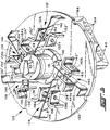
- a switch assembly indicated generally at 128 comprises a circuit board 130 which has a plurality of switches indicated generally at 132, 134, 136, 138, 140 and a plurality of connector terminals 164 which are interconnected to the switches by connector strips on the circuit board which are not visible in FIG. 5 as they are on the underside of the board with respect to FIG. 5.
- Each of the switches 132 through 140 has a contact blade 142 through 150 respectively each of which has the end thereof disposed to follow cam 46 which has a notch 151 formed therein with the end of contact blade 150 shown dropped into the notch in FIG. 5.
- Each of the contact blades 142 through 150 has provided thereon a double sided electrical contact as denoted by reference numeral 152 through 160.
- Each of the switches 132 through 140 also has a pair of oppositely disposed side contact denoted respectively 132a, 132b, 134a, 134b, 136a, 136b, 138a, 138b, and 140a, 140b which are mounted respectively on brackets 132', 132'', 134', 134'', 136', 136'', 138', 138'' and 140', 140''.
- Each of the brackets has a generally right angular configuration and is secured to the board 130 by tabs 162 provided thereon which extend through the board 130 and are soldered to the printed circuit on the underside thereof with respect to FIG. 5. Tabs 162 are not visible in FIG. 5, but are shown in FIG. 4.
- each of the contact blades 142 through 150 has the end thereof formed to a generally right angle configuration with tabs 162 provided thereon which extend through the circuit board and are soldered to strips provided thereon on the underside with respect to FIG. 5.
- tabs 162 With reference to FIG. 4, various protruding portions of these tabs 162 are shown extending through the circuit board to the upper surface thereof in FIG. 4. These tabs denoted by reference numeral 162 in FIG. 4 are soldered to the desired interconnecting strips (not shown) provided on the upper surface of the board 130.
- the cam surface 46 is set to maintain each of the switches 132 through 150 such that the contact blades 142 through 160 respectively are moved to close one of the side contacts associated respectively therewith; and, the cam notch 151 permits the end of a contact blade, for example contact blade 150, to drop therein causing the closed side contact to become open and the open contact to become closed in the manner of a single pole double throw (SPDT) switch.
- SPDT single pole double throw
- the contact blade 150 has its end dropped into cam notch 151 such that contact is broken between contact 160 and side contact 140b; and, contact has been made between the moveable contact 160 and the side contact 140a.
- Each of the switches 132 through 150 is electrically connected such that when the cam notch 151 is positioned to cause the respective contact blade to move, thereby opening the normally closed set of contacts, current flow to the motor is stopped and rotation of the shaft 48 is stopped.
- the valve member 28 is thus positioned such that the outlet port 30 is aligned with one of the outlet ports 21-29 in the body corresponding to the desired valve function.
- An electronic controller may be employed to bypass the open switch to the motor and restart the motor to cause rotation of the cam 46 to the next switch position, for example, to switch 132 and once again the motor current will be stopped when the end of the contact blade 142 drops into notch 151 thereby positioning the outlet port 30 on rotor 28 to a different one of the outlets 21 through 29.
- Each of the switches 132 through 140 is connected to appropriate ones of terminal pins 164 provided in a receptacle 166 mounted on the board 130, which pins are adapted for connection to an external wiring harness connector (not shown).
- the switch and circuit board assembly 128 is assembled into the cavity 70 on the motor housing as a subassembly and has the cam 46 preassembled thereon such that the stub shaft 41 is received in the aperture 50 in cover 52 and extends downwardly therethrough to engage the drive surface 42 in the valve member 28.
- the motor housing upper chamber 62 has a cover 168 received thereover and engaged therewith by any suitable expedient as for example snap locking into tabs 170 provided in the upper rim of cylindrical wall 64.
- the present invention thus provides a compact easy to manufacture and assemble and relatively low cost motorized diverter valve which has particular suitability for use in household automatic washing machines.
Landscapes
- Engineering & Computer Science (AREA)
- General Engineering & Computer Science (AREA)
- Mechanical Engineering (AREA)
- Electrically Driven Valve-Operating Means (AREA)
- Multiple-Way Valves (AREA)
- Mechanically-Actuated Valves (AREA)
Applications Claiming Priority (2)
| Application Number | Priority Date | Filing Date | Title |
|---|---|---|---|
| US08/751,011 US5848610A (en) | 1996-11-14 | 1996-11-14 | Motorized diverter valve |
| US751011 | 2000-12-29 |
Publications (2)
| Publication Number | Publication Date |
|---|---|
| EP0844422A2 true EP0844422A2 (de) | 1998-05-27 |
| EP0844422A3 EP0844422A3 (de) | 1998-10-07 |
Family
ID=25020094
Family Applications (1)
| Application Number | Title | Priority Date | Filing Date |
|---|---|---|---|
| EP97118763A Withdrawn EP0844422A3 (de) | 1996-11-14 | 1997-10-29 | Motorbetätigtes Umschaltventil |
Country Status (5)
| Country | Link |
|---|---|
| US (1) | US5848610A (de) |
| EP (1) | EP0844422A3 (de) |
| AU (1) | AU4513497A (de) |
| BR (1) | BR9706609A (de) |
| CA (1) | CA2218206A1 (de) |
Cited By (5)
| Publication number | Priority date | Publication date | Assignee | Title |
|---|---|---|---|---|
| EP1098122A1 (de) * | 1999-11-04 | 2001-05-09 | Eaton Corporation | Servomotorbetätigtes Ventil mit ultraschallgeschweisstem Gehäuse und Verfahren zur Herstellung |
| WO2002096683A1 (en) | 2001-05-25 | 2002-12-05 | Haldex Brake Corporation | Trailing arm suspension and height control system with motorized valve therefor |
| WO2009118308A1 (de) * | 2008-03-28 | 2009-10-01 | BSH Bosch und Siemens Hausgeräte GmbH | Wasserführendes haushaltsgerät |
| EP2816270A3 (de) * | 2013-06-21 | 2015-01-07 | Bitron Industrie Espana, S.A. | Motorisiertes Magnetventil |
| US11324382B2 (en) | 2020-02-21 | 2022-05-10 | Haier Us Appliance Solutions, Inc. | Diverter assembly for a dishwasher appliance and a method of operating the same |
Families Citing this family (19)
| Publication number | Priority date | Publication date | Assignee | Title |
|---|---|---|---|---|
| US6779557B2 (en) * | 2002-08-22 | 2004-08-24 | Mego Afek Industrial Measuring Instruments | Rotary disc valve |
| CA2450459A1 (en) * | 2001-06-13 | 2002-12-19 | Tri-Tech, Inc. | Linear valve actuator |
| US6932112B2 (en) * | 2002-08-26 | 2005-08-23 | Bradford, Iii Lawrence J. | Multiple port valve |
| ES2238139B1 (es) * | 2003-04-16 | 2006-12-01 | Fagor, S.Coop. | "distribuidor hidraulico para una lavadora de ropa". |
| KR100556779B1 (ko) * | 2003-12-05 | 2006-03-10 | 엘지전자 주식회사 | 식기세척기 |
| US20080155759A1 (en) * | 2006-12-27 | 2008-07-03 | Paul Douglas Mantle | Methods and apparatus for channeling liquid in a clothes treating apparatus |
| KR101315425B1 (ko) * | 2007-03-31 | 2013-10-07 | 엘지전자 주식회사 | 세탁기 |
| US7914625B2 (en) * | 2008-08-19 | 2011-03-29 | Whirlpool Corporation | Sequencing diverter valve system for an appliance |
| US8282741B2 (en) * | 2008-08-19 | 2012-10-09 | Whirlpool Corporation | Sequencing spray arm assembly for a dishwasher |
| CN102734529B (zh) * | 2012-07-13 | 2013-08-14 | 深圳市理邦精密仪器股份有限公司 | 一种联动控制装置及采用其的血气分析仪 |
| US9861258B2 (en) * | 2013-03-15 | 2018-01-09 | Whirlpool Corporation | Dishwasher |
| US10221952B2 (en) * | 2013-12-31 | 2019-03-05 | Samsung Electronics Co., Ltd. | Dish washing machine |
| CN104864119A (zh) * | 2014-02-21 | 2015-08-26 | 浙江三花旋转阀有限公司 | 一种旋转式流路切换阀 |
| US11739851B2 (en) | 2016-09-08 | 2023-08-29 | Illinois Tool Works Inc. | Clog resistant appliance diverter valve |
| US10094480B2 (en) * | 2017-01-24 | 2018-10-09 | Charles C. Partridge | Rotary multi-port valve |
| GB201821097D0 (en) * | 2018-12-21 | 2019-02-06 | Rotork Controls | Actuator |
| DE102020201190A1 (de) * | 2019-10-14 | 2021-04-15 | Vitesco Technologies GmbH | Fluidventil |
| CN112120629B (zh) * | 2020-08-31 | 2022-02-08 | 宁波方太厨具有限公司 | 一种清洗机 |
| US12013048B2 (en) * | 2021-12-15 | 2024-06-18 | Robert Bosch Llc | Rotary disc valve |
Family Cites Families (12)
| Publication number | Priority date | Publication date | Assignee | Title |
|---|---|---|---|---|
| US3802782A (en) * | 1970-08-19 | 1974-04-09 | Rohe Scientific Corp | Chemical analyzer performing sequential analysis of samples |
| US3757583A (en) * | 1971-02-08 | 1973-09-11 | Environment One Corp | Fluid sampling valve |
| US4195665A (en) * | 1978-02-24 | 1980-04-01 | Instrumentation Laboratory, Inc. | Fluid valve |
| US4326604A (en) * | 1979-10-15 | 1982-04-27 | Peter Sotiropoulos | Vehicle lubrication system |
| US4310022A (en) * | 1980-05-07 | 1982-01-12 | Givat Chaim-Ichud | Fluid distributor system |
| US4398562A (en) * | 1981-07-06 | 1983-08-16 | Richdel, Inc. | Motorized diverter valve |
| US4604093A (en) * | 1984-06-12 | 1986-08-05 | I-Flow Corporation | Apparatus and method for administering multiple fluid infusions |
| US4632148A (en) * | 1985-09-05 | 1986-12-30 | Stark Sr Robert G | Hydraulic distribution valve |
| AU615583B2 (en) * | 1988-10-21 | 1991-10-03 | Ashleigh Richard Pople | Water distribution device |
| DE9010608U1 (de) * | 1990-07-14 | 1990-09-20 | Meier, Hansjürgen, 4992 Espelkamp | Motorgesteuertes Mehrwegeventil |
| US5226454A (en) * | 1992-05-21 | 1993-07-13 | Hydrotech Chemical Corporation | DC motor actuated flow diversion valve |
| JPH0828726A (ja) * | 1994-07-20 | 1996-02-02 | Showa Tekko Kk | 多方弁の弁体回動停止装置 |
-
1996
- 1996-11-14 US US08/751,011 patent/US5848610A/en not_active Expired - Fee Related
-
1997
- 1997-10-29 EP EP97118763A patent/EP0844422A3/de not_active Withdrawn
- 1997-11-04 CA CA002218206A patent/CA2218206A1/en not_active Abandoned
- 1997-11-11 AU AU45134/97A patent/AU4513497A/en not_active Abandoned
- 1997-11-13 BR BR9706609A patent/BR9706609A/pt not_active Application Discontinuation
Non-Patent Citations (1)
| Title |
|---|
| None |
Cited By (6)
| Publication number | Priority date | Publication date | Assignee | Title |
|---|---|---|---|---|
| EP1098122A1 (de) * | 1999-11-04 | 2001-05-09 | Eaton Corporation | Servomotorbetätigtes Ventil mit ultraschallgeschweisstem Gehäuse und Verfahren zur Herstellung |
| WO2002096683A1 (en) | 2001-05-25 | 2002-12-05 | Haldex Brake Corporation | Trailing arm suspension and height control system with motorized valve therefor |
| CN100486826C (zh) * | 2001-05-25 | 2009-05-13 | 哈尔德克斯制动器公司 | 用于控制车辆心轴和车架之间距离的系统 |
| WO2009118308A1 (de) * | 2008-03-28 | 2009-10-01 | BSH Bosch und Siemens Hausgeräte GmbH | Wasserführendes haushaltsgerät |
| EP2816270A3 (de) * | 2013-06-21 | 2015-01-07 | Bitron Industrie Espana, S.A. | Motorisiertes Magnetventil |
| US11324382B2 (en) | 2020-02-21 | 2022-05-10 | Haier Us Appliance Solutions, Inc. | Diverter assembly for a dishwasher appliance and a method of operating the same |
Also Published As
| Publication number | Publication date |
|---|---|
| EP0844422A3 (de) | 1998-10-07 |
| US5848610A (en) | 1998-12-15 |
| MX9708817A (es) | 1998-08-30 |
| CA2218206A1 (en) | 1998-05-14 |
| BR9706609A (pt) | 1999-05-18 |
| AU4513497A (en) | 1998-05-21 |
Similar Documents
| Publication | Publication Date | Title |
|---|---|---|
| US5848610A (en) | Motorized diverter valve | |
| WO2003014845A2 (en) | Appliance control system with led operation indicators | |
| US5941502A (en) | Electric valve assembly and method of making same | |
| KR102179514B1 (ko) | 로터리식 3방향 밸브 | |
| US3575621A (en) | Drive means for appliance control means | |
| WO2003014843A2 (en) | Appliance control system with solid state appliance controller | |
| WO2003015252A2 (en) | Appliance control system with power controller | |
| CA2210995C (en) | Motor operated butterfly valve with a multi-function seal | |
| WO2003014841A2 (en) | Appliance control system with cycle selection detection | |
| US3761649A (en) | Multiturn rotary switch | |
| US5406158A (en) | Miniature synchronous motor | |
| US7202433B2 (en) | Appliance selector switch programmed by console cutout | |
| US6206043B1 (en) | CAM operated diverter valve | |
| CN204493766U (zh) | 一种阀开关组件 | |
| MXPA97008817A (en) | Motorizing device valve | |
| KR100392198B1 (ko) | 전동 볼밸브 | |
| US3286730A (en) | Pneumatic programmer | |
| CA2204269A1 (en) | Motorized sequencing switch assembly | |
| KR100250763B1 (ko) | 회전밸브축과 더불어 사용되는 밀봉된 스위치 조립물 | |
| KR102698132B1 (ko) | 차량용 밸브 액추에이터 | |
| CN219629344U (zh) | 一种气泡水机 | |
| US5736699A (en) | Elecro-mechanical programmer/timer | |
| US6064011A (en) | Appliance timer having an auxiliary switching assembly for increasing switching capacity and associated method | |
| KR100373551B1 (ko) | 타임 스위치 | |
| US6844513B2 (en) | Appliance timer |
Legal Events
| Date | Code | Title | Description |
|---|---|---|---|
| PUAI | Public reference made under article 153(3) epc to a published international application that has entered the european phase |
Free format text: ORIGINAL CODE: 0009012 |
|
| AK | Designated contracting states |
Kind code of ref document: A2 Designated state(s): DE ES FR GB IT SE |
|
| PUAL | Search report despatched |
Free format text: ORIGINAL CODE: 0009013 |
|
| AK | Designated contracting states |
Kind code of ref document: A3 Designated state(s): AT BE CH DE DK ES FI FR GB GR IE IT LI LU MC NL PT SE |
|
| AKX | Designation fees paid | ||
| 17P | Request for examination filed |
Effective date: 19990602 |
|
| RBV | Designated contracting states (corrected) |
Designated state(s): DE ES FR GB IT SE |
|
| 17Q | First examination report despatched |
Effective date: 20021001 |
|
| STAA | Information on the status of an ep patent application or granted ep patent |
Free format text: STATUS: THE APPLICATION IS DEEMED TO BE WITHDRAWN |
|
| 18D | Application deemed to be withdrawn |
Effective date: 20030212 |