EP0843452B1 - Telefonhörer mit verringerter Dicke der Hörmuschel - Google Patents
Telefonhörer mit verringerter Dicke der Hörmuschel Download PDFInfo
- Publication number
- EP0843452B1 EP0843452B1 EP97402657A EP97402657A EP0843452B1 EP 0843452 B1 EP0843452 B1 EP 0843452B1 EP 97402657 A EP97402657 A EP 97402657A EP 97402657 A EP97402657 A EP 97402657A EP 0843452 B1 EP0843452 B1 EP 0843452B1
- Authority
- EP
- European Patent Office
- Prior art keywords
- wall
- space
- assembly
- casing
- telephone handset
- Prior art date
- Legal status (The legal status is an assumption and is not a legal conclusion. Google has not performed a legal analysis and makes no representation as to the accuracy of the status listed.)
- Expired - Lifetime
Links
Images
Classifications
-
- H—ELECTRICITY
- H04—ELECTRIC COMMUNICATION TECHNIQUE
- H04R—LOUDSPEAKERS, MICROPHONES, GRAMOPHONE PICK-UPS OR LIKE ACOUSTIC ELECTROMECHANICAL TRANSDUCERS; ELECTRIC HEARING AIDS; PUBLIC ADDRESS SYSTEMS
- H04R1/00—Details of transducers, loudspeakers or microphones
- H04R1/20—Arrangements for obtaining desired frequency or directional characteristics
- H04R1/22—Arrangements for obtaining desired frequency or directional characteristics for obtaining desired frequency characteristic only
- H04R1/28—Transducer mountings or enclosures modified by provision of mechanical or acoustic impedances, e.g. resonator, damping means
- H04R1/2807—Enclosures comprising vibrating or resonating arrangements
- H04R1/2838—Enclosures comprising vibrating or resonating arrangements of the bandpass type
- H04R1/2842—Enclosures comprising vibrating or resonating arrangements of the bandpass type for loudspeaker transducers
-
- H—ELECTRICITY
- H04—ELECTRIC COMMUNICATION TECHNIQUE
- H04M—TELEPHONIC COMMUNICATION
- H04M1/00—Substation equipment, e.g. for use by subscribers
- H04M1/02—Constructional features of telephone sets
- H04M1/03—Constructional features of telephone transmitters or receivers, e.g. telephone hand-sets
- H04M1/035—Improving the acoustic characteristics by means of constructional features of the housing, e.g. ribs, walls, resonating chambers or cavities
-
- H—ELECTRICITY
- H04—ELECTRIC COMMUNICATION TECHNIQUE
- H04R—LOUDSPEAKERS, MICROPHONES, GRAMOPHONE PICK-UPS OR LIKE ACOUSTIC ELECTROMECHANICAL TRANSDUCERS; ELECTRIC HEARING AIDS; PUBLIC ADDRESS SYSTEMS
- H04R2499/00—Aspects covered by H04R or H04S not otherwise provided for in their subgroups
- H04R2499/10—General applications
- H04R2499/11—Transducers incorporated or for use in hand-held devices, e.g. mobile phones, PDA's, camera's
Definitions
- the present invention relates to a handset telephone and concerns the listener part of such combined.
- the purpose of the invention is to reduce the thickness of a such handset at the level of the earpiece part.
- the invention applies, in particular, to handsets mobile phones. It is indeed particularly necessary to reduce the volume and more specifically the thickness of such devices since they are intended for to be carried in a pocket of their user.
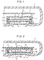
- FIG. 1 A known telephone handset, in its earphone part is shown in FIG. 1. It comprises a housing 1 in which is mounted a capsule earphone 2.
- This earphone capsule is essentially constituted of a piezoelectric disk 3 (ceramic) stuck on a metal disc 4.
- Variations of AC voltage applied to the terminals of this set generate a alternating vibration of the set at the same frequency as voltage variations and thus produces waves of sound pressure.
- the response curve of the system representing the amplitude of the sound vibrations in function of the excitation frequency has a peak corresponding to its natural frequency (around 1000 Hz) and a significant weakening beyond this frequency.
- the disc 3 is sandwiched between two parts 5 and 6 forming a capsule 2 and the rear wall 6 is pierced with a hole 7 closed by a fabric 8 whose role is to form micro-holes creating a resistance acoustic.
- the Helmoltz resonator for the amplification of treble consists of volume 9 between the disc 4 and the part 5 and some holes 10 of a diameter of the order of 1 mm in the front wall of part 5.
- the printed circuit board 11 supporting the different electronic components 12 of the handset can not so not be placed at a distance less than this x value of the back wall of the capsule 2.
- a circular seal with a thickness e of about 1 mm.
- the present invention aims to propose a handset in which the earphone part is less thick. This is therefore a structural provision to reduce this thickness.
- a handset with preamble features of claim 1 is known from FR-A-2665045.
- the invention thus relates to a telephone handset having at least one earphone part and comprising a housing, said housing containing at least one piezoelectric disc linked to an electrically support disc conductor, said support disk being held tightly on its periphery between two pieces of support and separating a first volume, called rear volume, delimited on the one hand by the set formed by the piezoelectric disk and its disc support and secondly by a rear wall vis-à-vis said assembly and a circular side wall, the rear wall and side wall constituting a room rear part, said rear part being arranged so as to allow the passage of micro-leaks to constitute with the rear volume an acoustic damper device, and a second volume, called front volume, located on the other side said assembly and constituting, with holes drilled in a wall of said front volume facing said assembly, a Helmoltz resonator, characterized in that said housing further contains a component support plate directly applied against the wall rear of said rear volume.
- said wall of said front volume facing said set belongs to audit housing itself and constitutes the part of the wall of the housing intended to be applied against the ear of the user, said front volume also having a circular side wall delimiting said volume, said side wall belonging to said housing.
- said micro-leaks are arranged in said rear piece of way to evacuate by side slits.
- Figure 1 schematically represents a view partial sectional view of the earpiece part of a handset telephone of the prior art described above.
- Figure 2 is the equivalent of Figure 1 but a telephone handset according to the invention.
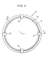
- the referenced part 14, shown in isolation FIG. 3, is seen in section according to A-A of FIG.
- FIG. 3 shows separately in view from below the part called back piece of FIG. 2 and referenced 14.
- this handset includes an outer housing 1 containing all the organs of the handset and in particular the earpiece part whose sound source transforming electrical signals into a vibrating body producing sound pressure waves is constituted of a piezo-electric disk 3 in ceramic glued, using an electrically conductive adhesive, to a support disc 4 electrically conductive.
- the electric tension Representative alternative of the sound to be reproduced is applied between these two members by wires, not shown, welded to these organs.
- the case also contains, among others, a platinum 11 support of various electronic components 12 necessary for the operation of the handset.
- vibrating sound transmitter constituted by the whole formed of the piezoelectric disk 3 and its support disk 4 is enclosed in a capsule 2 disposed in the housing 1.
- this piezoelectric disk assembly 3 with its support disc 4 is placed in a capsule integrated to the housing 1.
- Set 3-4 called vibrating and referenced set 13, is in fact held in place in the housing 1 by the periphery of the support disc 4 clamped between two pieces of maintenance of which one 14 is called back piece and of which the other is part of the housing 1 and consists of a circular side wall 15.
- the vibrating assembly 13 separates a first volume 16, called volume back, of a second volume 17, called volume before.
- the first volume 16 is delimited on the one hand by the vibrating assembly 13 and secondly by said part rear 14 comprising a rear wall 18 vis-à-vis the assembly 13 and a circular side wall 19.
- the volume before 17 is delimited by this same set 13, a wall 20 facing said assembly and belonging to the housing 1 and said circular side wall 15.
- This volume before 17, constitutes, with holes 21 drilled in the wall 20 a Helmoltz resonator for the amplification of the high frequencies.
- the holes 21 have, by for example, a diameter of the order of a millimeter.
- an acoustic damper is created by realizing micro-leaks in a wall of the rear volume 16.
- these micro-leaks are carried out by lateral slits 22.
- these slots 22 result on the one hand, of notches 23 made in the side wall 19 of the rear piece 14, notches that bite a little bit in the thickness of the wall 18 of this rear piece 14, and on the other hand, the interruption of support at the level of these notches, of the back piece 14, against a side wall 15 A belonging to the housing 1.
- These slots 22 are by example in number of 4 and have a very small thickness by example of 0.08 mm. Micro-leaks through these slots laterally 22 escape laterally and one can thus directly apply the support plate 11 against the wall 18 of the back piece 14. This saves the space x of FIG. 1, which reduces the thickness of the thickness housing 1.
- the space x was 1 to 2 mm.
- the fact that the "capsule" is integrated into the housing also saves, on the one hand the seal e of Figure 1, 1 mm, and on the other hand the thickness e 1 of the bottom wall , about 0.5 mm, of the capsule 2 of the same prior art ( Figure 1).
Landscapes
- Engineering & Computer Science (AREA)
- Signal Processing (AREA)
- Health & Medical Sciences (AREA)
- Otolaryngology (AREA)
- Physics & Mathematics (AREA)
- Acoustics & Sound (AREA)
- Telephone Set Structure (AREA)
- Obtaining Desirable Characteristics In Audible-Bandwidth Transducers (AREA)
Claims (4)
- Telefonhörer, der mindestens einen Hörmuschelteil umfasst und ein Gehäuse (1) aufweist, wobei das besagte Gehäuse mindestens eine Piezokristallplatte (3) enthält, die mit einer elektrisch leitenden Trägerscheibe (4) verbunden ist, wobei die besagte Trägerscheibe an ihrem Rand zwischen zwei Halteteilen (14, 15) eingeklemmt gehalten wird und dabei einen ersten Raum abteilt, hinterer Raum (16) genannt, der einerseits von der Konstruktion abgegrenzt wird, die von der Piezokristallplatte (3) und ihrer Trägerscheibe (4) und andererseits von einer Rückwand gegenüber der besagten Konstruktion (3, 4) und einer kreisförmigen Seitenwand (19) gebildet wird, wobei die Rückwand und die Seitenwand ein Hinterteil (14) bilden, wobei das besagte Hinterteil (14) so ausgestaltet ist, dass Mikrodurchlässe eingearbeitet werden können, um mit dem hinteren Raum (16) eine Vorrichtung zur akustischen Dämpfung zu bilden, und einen zweiten Raum, vorderer Raum (17) genannt, der sich auf der anderen Seite der besagten Konstruktion befindet und mit seinen Löchern (21), die in die Wand (20) des besagten vorderen Raums eingearbeitet sind, die der besagten Konstruktion (3-4) gegenüberliegt, einen Helmholtz-Resonator bildet, dadurch gekennzeichnet, dass das besagte Gehäuse außerdem eine Trägerplatine (11) mit elektronischen Bauteilen (12) enthält, die direkt an der Rückwand (18) des besagten hinteren Raums (16) anliegt.
- Telefonhörer nach Anspruch 1, dadurch gekennzeichnet, dass die besagte Wand (20) des besagten vorderen Raums (17), die der besagten Konstruktion (3-4) gegenüberliegt, zu besagtem Gehäuse (1) selbst gehört und den Teil der Wand des Gehäuses darstellt, der dazu bestimmt ist, gegen das Ohr des Nutzers gedrückt zu werden, wobei der besagte vordere Raum (17) ebenfalls eine kreisförmige Seitenwand (15) umfasst, die den besagten vorderen Raum abgrenzt, wobei die besagte Seitenwand (15) zum besagten Gehäuse gehört.
- Telefonhörer nach Anspruch 1 oder 2, dadurch gekennzeichnet, dass die besagten Mikrodurchlässe in das besagte Hinterteil (14) so eingearbeitet sind, dass sie durch Seitenschlitze (22) verlaufen.
- Telefonhörer nach Anspruch 1 oder 2, dadurch gekennzeichnet, dass die besagten Mikrodurchlässe durch die besagte Rückwand (18) des besagten Hinterteils (14) und die besagte Trägerplatine (11) eingearbeitet sind.
Applications Claiming Priority (2)
| Application Number | Priority Date | Filing Date | Title |
|---|---|---|---|
| FR9613870A FR2755813B1 (fr) | 1996-11-14 | 1996-11-14 | Combine telephonique |
| FR9613870 | 1996-11-14 |
Publications (2)
| Publication Number | Publication Date |
|---|---|
| EP0843452A1 EP0843452A1 (de) | 1998-05-20 |
| EP0843452B1 true EP0843452B1 (de) | 2005-03-16 |
Family
ID=9497608
Family Applications (1)
| Application Number | Title | Priority Date | Filing Date |
|---|---|---|---|
| EP97402657A Expired - Lifetime EP0843452B1 (de) | 1996-11-14 | 1997-11-06 | Telefonhörer mit verringerter Dicke der Hörmuschel |
Country Status (7)
| Country | Link |
|---|---|
| US (1) | US5953414A (de) |
| EP (1) | EP0843452B1 (de) |
| JP (1) | JPH10229435A (de) |
| CA (1) | CA2219152A1 (de) |
| DE (1) | DE69732756T2 (de) |
| ES (1) | ES2239778T3 (de) |
| FR (1) | FR2755813B1 (de) |
Cited By (1)
| Publication number | Priority date | Publication date | Assignee | Title |
|---|---|---|---|---|
| US11506382B2 (en) | 2019-09-12 | 2022-11-22 | General Electric Company | System and method for acoustic dampers with multiple volumes in a combustion chamber front panel |
Families Citing this family (34)
| Publication number | Priority date | Publication date | Assignee | Title |
|---|---|---|---|---|
| GB2333004B (en) * | 1997-12-31 | 2002-03-27 | Nokia Mobile Phones Ltd | Earpiece acoustics |
| DK174546B1 (da) * | 1998-12-21 | 2003-05-19 | Sony Ericsson Mobile Comm Ab | Et kommunikationsapparat |
| JP2002536891A (ja) * | 1999-01-26 | 2002-10-29 | コーニンクレッカ フィリップス エレクトロニクス エヌ ヴィ | 音声変成器を収容し、通路を有するハウジングを持つ装置 |
| FI114079B (fi) * | 1999-05-07 | 2004-07-30 | Nokia Corp | Pietsosähköinen audiolaite ja menetelmä äänen tuottamiseen |
| US6282287B1 (en) * | 1999-07-06 | 2001-08-28 | Chung-Yu Lin | Communication earpiece without impulse and high frequency noise |
| GB0123451D0 (en) * | 2001-09-28 | 2001-11-21 | Mitel Knowledge Corp | Device for reducing structural-acoustical coupling between the diaphragm vibration field and the enclosure acoustic modes |
| GB0213732D0 (en) * | 2002-06-14 | 2002-07-24 | Mitel Knowledge Corp | Audio earpiece for wideband telephone handsets |
| JP2004129192A (ja) * | 2002-07-29 | 2004-04-22 | Hosiden Corp | レシーバユニット |
| JP3907616B2 (ja) * | 2003-10-03 | 2007-04-18 | 太陽誘電株式会社 | 電子機器 |
| GB2408405A (en) * | 2003-11-18 | 2005-05-25 | Sonaptic Ltd | Sonic emitter |
| GB0328639D0 (en) | 2003-12-10 | 2004-01-14 | Mitel Networks Corp | Loudspeaker enclosure incorporating a leak to compensate for the effect of acoustic modes on loudspeaker frequency response |
| TWI254588B (en) * | 2004-03-18 | 2006-05-01 | Cotron Corp | Speaker module frame, speaker module therewith, and electrical device with the speaker module |
| GB2426405B (en) * | 2005-05-21 | 2008-02-27 | Sonaptic Ltd | Miniature planar acoustic networks |
| US8090136B2 (en) | 2005-07-29 | 2012-01-03 | Research In Motion Limited | Handheld electronic device having offset sound openings |
| EP2114083A1 (de) | 2005-07-29 | 2009-11-04 | Research In Motion Limited | Tragbare elektronische Vorrichtung mit Offsettonöffnungen |
| US7556121B2 (en) * | 2006-12-15 | 2009-07-07 | Foxconn Technology Co., Ltd. | Speaker set and mobile phone incorporating the same |
| US7578368B2 (en) * | 2007-03-07 | 2009-08-25 | Foxconn Technology Co., Ltd. | Speaker set for electronic product |
| US7578367B2 (en) * | 2007-03-07 | 2009-08-25 | Foxconn Technology Co., Ltd. | Speaker set and electronic product incorporating the same |
| US8891802B2 (en) * | 2008-05-02 | 2014-11-18 | Blackberry Limited | Enclosure and enclosure system for a speaker of an electronic device |
| FR2934738B1 (fr) * | 2008-08-04 | 2011-07-29 | Sagem Comm | Combine telephonique sans fil ayant une chaine electroacoustique a large bande passante. |
| US8126170B2 (en) | 2008-09-05 | 2012-02-28 | Apple Inc. | Electromagnetic interference shields with piezos |
| US8265329B2 (en) * | 2008-09-05 | 2012-09-11 | Apple Inc. | Compact housing for portable electronic device with internal speaker |
| US20100246143A1 (en) * | 2009-03-26 | 2010-09-30 | Richard Hung Minh Dinh | Electromagnetic Interference Shielding for Compact Electronic Devices |
| WO2011015236A1 (en) * | 2009-08-04 | 2011-02-10 | Nokia Corporation | An apparatus |
| KR101573517B1 (ko) * | 2009-10-12 | 2015-12-02 | 삼성전자주식회사 | 압전형 마이크로 스피커 |
| US8557106B2 (en) | 2010-09-30 | 2013-10-15 | Exxonmobil Research And Engineering Company | Hydrocracking process selective for improved distillate and improved lube yield and properties |
| WO2014098820A1 (en) | 2012-12-19 | 2014-06-26 | Exxonmobil Research And Engineering Company | Mesoporous zeolite -y hydrocracking catalyst and associated hydrocracking processes |
| US9301040B2 (en) * | 2014-03-14 | 2016-03-29 | Bose Corporation | Pressure equalization in earphones |
| US10221769B2 (en) | 2016-12-02 | 2019-03-05 | General Electric Company | System and apparatus for gas turbine combustor inner cap and extended resonating tubes |
| US10228138B2 (en) | 2016-12-02 | 2019-03-12 | General Electric Company | System and apparatus for gas turbine combustor inner cap and resonating tubes |
| US10220474B2 (en) | 2016-12-02 | 2019-03-05 | General Electricd Company | Method and apparatus for gas turbine combustor inner cap and high frequency acoustic dampers |
| KR102366760B1 (ko) * | 2017-09-14 | 2022-02-22 | 엘지디스플레이 주식회사 | 표시장치 |
| JP7600522B2 (ja) * | 2019-12-25 | 2024-12-17 | ヤマハ株式会社 | スピーカーおよび車両 |
| CN112261187B (zh) * | 2020-10-23 | 2022-04-12 | 维沃移动通信有限公司 | 电子设备 |
Family Cites Families (12)
| Publication number | Priority date | Publication date | Assignee | Title |
|---|---|---|---|---|
| US3952159A (en) * | 1973-03-09 | 1976-04-20 | Zenith Radio Corporation | Ducted port reflex enclosure |
| US4006371A (en) * | 1973-03-19 | 1977-02-01 | Whitewater Electronics, Inc. | Electroacoustical transducer comprising piezoelectric element |
| JPS60218998A (ja) * | 1984-04-16 | 1985-11-01 | Matsushita Electric Ind Co Ltd | スピ−カ |
| FR2643771A1 (fr) * | 1989-02-27 | 1990-08-31 | Horlogerie Photograph Fse | Capsule piezoelectrique a organes de maintien elastiques conducteurs |
| ATE116782T1 (de) * | 1990-05-14 | 1995-01-15 | Alcatel Dial Face Spa | Piezoelektrischer wandler. |
| US5081674A (en) * | 1990-05-14 | 1992-01-14 | Motorola, Inc. | Double annular ring speaker gasket |
| FR2665045B3 (fr) * | 1990-07-19 | 1992-12-18 | Matra Communication | Transducteur electro-acoustique a disque piezo-electrique, combine telephonique incorporant un tel transducteur et procede de fabrication d'un tel combine. |
| US5201069A (en) * | 1991-10-18 | 1993-04-06 | Motorola, Inc. | Electroacoustic transducer mounting apparatus |
| EP0595514B1 (de) * | 1992-10-27 | 2003-06-25 | TDK Corporation | Piezoelektrischer Wandler |
| US5729605A (en) * | 1995-06-19 | 1998-03-17 | Plantronics, Inc. | Headset with user adjustable frequency response |
| JPH0946794A (ja) * | 1995-07-31 | 1997-02-14 | Taiyo Yuden Co Ltd | 圧電音響装置 |
| US5790679A (en) * | 1996-06-06 | 1998-08-04 | Northern Telecom Limited | Communications terminal having a single transducer for handset and handsfree receive functionality |
-
1996
- 1996-11-14 FR FR9613870A patent/FR2755813B1/fr not_active Expired - Fee Related
-
1997
- 1997-11-06 EP EP97402657A patent/EP0843452B1/de not_active Expired - Lifetime
- 1997-11-06 DE DE69732756T patent/DE69732756T2/de not_active Expired - Lifetime
- 1997-11-06 ES ES97402657T patent/ES2239778T3/es not_active Expired - Lifetime
- 1997-11-10 US US08/966,978 patent/US5953414A/en not_active Expired - Lifetime
- 1997-11-13 JP JP9311845A patent/JPH10229435A/ja active Pending
- 1997-11-13 CA CA002219152A patent/CA2219152A1/fr not_active Abandoned
Cited By (1)
| Publication number | Priority date | Publication date | Assignee | Title |
|---|---|---|---|---|
| US11506382B2 (en) | 2019-09-12 | 2022-11-22 | General Electric Company | System and method for acoustic dampers with multiple volumes in a combustion chamber front panel |
Also Published As
| Publication number | Publication date |
|---|---|
| DE69732756D1 (de) | 2005-04-21 |
| US5953414A (en) | 1999-09-14 |
| ES2239778T3 (es) | 2005-10-01 |
| CA2219152A1 (fr) | 1998-05-14 |
| FR2755813A1 (fr) | 1998-05-15 |
| FR2755813B1 (fr) | 1998-12-11 |
| EP0843452A1 (de) | 1998-05-20 |
| JPH10229435A (ja) | 1998-08-25 |
| DE69732756T2 (de) | 2006-04-13 |
Similar Documents
| Publication | Publication Date | Title |
|---|---|---|
| EP0843452B1 (de) | Telefonhörer mit verringerter Dicke der Hörmuschel | |
| EP0067790B1 (de) | Gemischter elektro-akustischer Wandler | |
| FR2504343A1 (fr) | Prothese auditive | |
| FR2487619A1 (fr) | Transducteur electroacoustique bivoie, en particulier pour casques et microphones | |
| FR2500248A1 (fr) | Auxiliaire d'audition du type a porter derriere l'oreille | |
| CN1166767A (zh) | 无线电话的扬声器装置 | |
| EP1154618B1 (de) | Mobiltelefon mit Unterdrückung des Hintergrundgeräusches | |
| FR2715526A1 (fr) | Dispositif de production de signaux acoustiques, transmissibles par voie téléphonique. | |
| WO2022136807A1 (fr) | Casque audio a reduction de bruit active | |
| FR2783652A1 (fr) | Telephone mobile a ecoute amplifiee | |
| EP1665870A2 (de) | Schallwiedergebender wandler | |
| EP1244277B1 (de) | Freisprechtelefongerät mit verbesserter Lecktoleranz | |
| CA2145629C (fr) | Transducteur electro-acoustique a volume diffusant | |
| FR2934738A1 (fr) | Combine telephonique sans fil ayant une chaine electroacoustique a large bande passante. | |
| WO2019166705A1 (fr) | Dispositif vibroacoustique | |
| FR2617660A1 (fr) | Dispositif de prise et de restitution du son, notamment pour audio-conferences | |
| CH558119A (de) | Enceinte munie de haut-parleurs. | |
| EP0649269B1 (de) | Lautsprechergehäuse mit erweiterter Diffusion | |
| EP2577989B1 (de) | Akustischer lautsprecher | |
| FR2545302A1 (fr) | Filtre acoustique pour transducteur en particulier du type electromagnetique de combine telephonique | |
| KR102312006B1 (ko) | 마이크 실장 이어폰 | |
| FR2713867A1 (fr) | Dispositif pour la réalisation d'une sonorisation individuelle de proximité. | |
| FR2820935A1 (fr) | Dispositif d'emission acoustique etanche | |
| WO2007080346A1 (fr) | Telephone bande elargie a deux ecouteurs | |
| EP4386741A1 (de) | Elektromechanische vorrichtung mit variabler resonanzfrequenz und akustische vorrichtung damit |
Legal Events
| Date | Code | Title | Description |
|---|---|---|---|
| PUAI | Public reference made under article 153(3) epc to a published international application that has entered the european phase |
Free format text: ORIGINAL CODE: 0009012 |
|
| AK | Designated contracting states |
Kind code of ref document: A1 Designated state(s): DE ES FR GB IT |
|
| 17P | Request for examination filed |
Effective date: 19981022 |
|
| AKX | Designation fees paid |
Free format text: DE ES FR GB IT |
|
| RBV | Designated contracting states (corrected) |
Designated state(s): DE ES FR GB IT |
|
| RAP3 | Party data changed (applicant data changed or rights of an application transferred) |
Owner name: ALCATEL |
|
| RAP3 | Party data changed (applicant data changed or rights of an application transferred) |
Owner name: ALCATEL |
|
| 17Q | First examination report despatched |
Effective date: 20030908 |
|
| GRAP | Despatch of communication of intention to grant a patent |
Free format text: ORIGINAL CODE: EPIDOSNIGR1 |
|
| GRAA | (expected) grant |
Free format text: ORIGINAL CODE: 0009210 |
|
| GRAS | Grant fee paid |
Free format text: ORIGINAL CODE: EPIDOSNIGR3 |
|
| AK | Designated contracting states |
Kind code of ref document: B1 Designated state(s): DE ES FR GB IT |
|
| REG | Reference to a national code |
Ref country code: GB Ref legal event code: FG4D Free format text: NOT ENGLISH |
|
| REF | Corresponds to: |
Ref document number: 69732756 Country of ref document: DE Date of ref document: 20050421 Kind code of ref document: P |
|
| GBT | Gb: translation of ep patent filed (gb section 77(6)(a)/1977) |
Effective date: 20050615 |
|
| REG | Reference to a national code |
Ref country code: ES Ref legal event code: FG2A Ref document number: 2239778 Country of ref document: ES Kind code of ref document: T3 |
|
| PGFP | Annual fee paid to national office [announced via postgrant information from national office to epo] |
Ref country code: ES Payment date: 20051219 Year of fee payment: 9 |
|
| PLBE | No opposition filed within time limit |
Free format text: ORIGINAL CODE: 0009261 |
|
| STAA | Information on the status of an ep patent application or granted ep patent |
Free format text: STATUS: NO OPPOSITION FILED WITHIN TIME LIMIT |
|
| 26N | No opposition filed |
Effective date: 20051219 |
|
| REG | Reference to a national code |
Ref country code: FR Ref legal event code: TP |
|
| REG | Reference to a national code |
Ref country code: ES Ref legal event code: FD2A Effective date: 20061107 |
|
| PG25 | Lapsed in a contracting state [announced via postgrant information from national office to epo] |
Ref country code: ES Free format text: LAPSE BECAUSE OF NON-PAYMENT OF DUE FEES Effective date: 20061107 |
|
| REG | Reference to a national code |
Ref country code: GB Ref legal event code: 732E Free format text: REGISTERED BETWEEN 20090924 AND 20090930 |
|
| REG | Reference to a national code |
Ref country code: GB Ref legal event code: 732E Free format text: REGISTERED BETWEEN 20120607 AND 20120613 |
|
| REG | Reference to a national code |
Ref country code: FR Ref legal event code: TP Owner name: Z124, GB Effective date: 20130201 Ref country code: FR Ref legal event code: CD Owner name: Z124, GB Effective date: 20130201 |
|
| REG | Reference to a national code |
Ref country code: FR Ref legal event code: PLFP Year of fee payment: 19 |
|
| REG | Reference to a national code |
Ref country code: FR Ref legal event code: PLFP Year of fee payment: 20 |
|
| PGFP | Annual fee paid to national office [announced via postgrant information from national office to epo] |
Ref country code: GB Payment date: 20161027 Year of fee payment: 20 Ref country code: FR Payment date: 20161024 Year of fee payment: 20 Ref country code: DE Payment date: 20161020 Year of fee payment: 20 |
|
| PGFP | Annual fee paid to national office [announced via postgrant information from national office to epo] |
Ref country code: IT Payment date: 20161025 Year of fee payment: 20 |
|
| REG | Reference to a national code |
Ref country code: DE Ref legal event code: R071 Ref document number: 69732756 Country of ref document: DE |
|
| REG | Reference to a national code |
Ref country code: GB Ref legal event code: PE20 Expiry date: 20171105 |
|
| PG25 | Lapsed in a contracting state [announced via postgrant information from national office to epo] |
Ref country code: GB Free format text: LAPSE BECAUSE OF EXPIRATION OF PROTECTION Effective date: 20171105 |