EP0843370A1 - Wassernachfüllstopfen für einen flüssigen Elektrolyten enthaltende Batterien - Google Patents
Wassernachfüllstopfen für einen flüssigen Elektrolyten enthaltende Batterien Download PDFInfo
- Publication number
- EP0843370A1 EP0843370A1 EP97119743A EP97119743A EP0843370A1 EP 0843370 A1 EP0843370 A1 EP 0843370A1 EP 97119743 A EP97119743 A EP 97119743A EP 97119743 A EP97119743 A EP 97119743A EP 0843370 A1 EP0843370 A1 EP 0843370A1
- Authority
- EP
- European Patent Office
- Prior art keywords
- water
- valve
- plug housing
- plug
- housing
- Prior art date
- Legal status (The legal status is an assumption and is not a legal conclusion. Google has not performed a legal analysis and makes no representation as to the accuracy of the status listed.)
- Granted
Links
Images


Classifications
-
- F—MECHANICAL ENGINEERING; LIGHTING; HEATING; WEAPONS; BLASTING
- F16—ENGINEERING ELEMENTS AND UNITS; GENERAL MEASURES FOR PRODUCING AND MAINTAINING EFFECTIVE FUNCTIONING OF MACHINES OR INSTALLATIONS; THERMAL INSULATION IN GENERAL
- F16K—VALVES; TAPS; COCKS; ACTUATING-FLOATS; DEVICES FOR VENTING OR AERATING
- F16K31/00—Actuating devices; Operating means; Releasing devices
- F16K31/12—Actuating devices; Operating means; Releasing devices actuated by fluid
- F16K31/18—Actuating devices; Operating means; Releasing devices actuated by fluid actuated by a float
- F16K31/20—Actuating devices; Operating means; Releasing devices actuated by fluid actuated by a float actuating a lift valve
-
- H—ELECTRICITY
- H01—ELECTRIC ELEMENTS
- H01M—PROCESSES OR MEANS, e.g. BATTERIES, FOR THE DIRECT CONVERSION OF CHEMICAL ENERGY INTO ELECTRICAL ENERGY
- H01M50/00—Constructional details or processes of manufacture of the non-active parts of electrochemical cells other than fuel cells, e.g. hybrid cells
- H01M50/60—Arrangements or processes for filling or topping-up with liquids; Arrangements or processes for draining liquids from casings
- H01M50/609—Arrangements or processes for filling with liquid, e.g. electrolytes
- H01M50/627—Filling ports
-
- Y—GENERAL TAGGING OF NEW TECHNOLOGICAL DEVELOPMENTS; GENERAL TAGGING OF CROSS-SECTIONAL TECHNOLOGIES SPANNING OVER SEVERAL SECTIONS OF THE IPC; TECHNICAL SUBJECTS COVERED BY FORMER USPC CROSS-REFERENCE ART COLLECTIONS [XRACs] AND DIGESTS
- Y02—TECHNOLOGIES OR APPLICATIONS FOR MITIGATION OR ADAPTATION AGAINST CLIMATE CHANGE
- Y02E—REDUCTION OF GREENHOUSE GAS [GHG] EMISSIONS, RELATED TO ENERGY GENERATION, TRANSMISSION OR DISTRIBUTION
- Y02E60/00—Enabling technologies; Technologies with a potential or indirect contribution to GHG emissions mitigation
- Y02E60/10—Energy storage using batteries
-
- Y—GENERAL TAGGING OF NEW TECHNOLOGICAL DEVELOPMENTS; GENERAL TAGGING OF CROSS-SECTIONAL TECHNOLOGIES SPANNING OVER SEVERAL SECTIONS OF THE IPC; TECHNICAL SUBJECTS COVERED BY FORMER USPC CROSS-REFERENCE ART COLLECTIONS [XRACs] AND DIGESTS
- Y10—TECHNICAL SUBJECTS COVERED BY FORMER USPC
- Y10T—TECHNICAL SUBJECTS COVERED BY FORMER US CLASSIFICATION
- Y10T137/00—Fluid handling
- Y10T137/4673—Plural tanks or compartments with parallel flow
- Y10T137/4757—Battery or electrolytic cell replenishment
Definitions
- the invention relates to a water refill plug for a liquid Batteries containing electrolytes according to the preamble of the claim 1.
- a previously known water refill plug of this type (DE-295 11 994 U, EP 96 109 776 A1) is the valve seat on a separate from the plug housing Lid-like component is provided, which is plug-like in an open valve housing inserted and held by clamping is.
- a disadvantage of this known arrangement is that, for example when freezing water in the valve housing and the resulting associated expansion processes the valve seat component from the plug housing can solve, at least the effectiveness of the valve largely eliminated and there is an overflow of the existing ones in the battery Acid can come.
- the manufacture of the known Water refill plug is expensive, especially because of the requirement to manufacture the valve seat component in one special operation. Because of the multitude of over the scope Distributed slots on the valve seat component is also its manufacture complex.
- the aim of the present invention is to provide a water refill plug to create the genus mentioned, in which an undesirable Solution of the valve seat from the plug housing is excluded and which is easier due to a smaller number of components and is more economical to manufacture and assemble.
- the Functional reliability of the water refill plug can be increased.
- the valve seat component thus forms an integrating one Part of the plug housing itself, so that even with vibrations and / or frost a solution of the valve seat component from Plug housing is excluded.
- a significant structural advantage is also achieved in that a separately manufactured and then assembled with the plug housing Valve seat component is avoided by being in the Plug housing is integrated.
- valve seat designed as an integral component containing valve chamber. Only the valve body with the one preferably provided on it Valve rod is still to be manufactured as a separate component, which, however, by simply inserting it into the valve chamber from the outside is mountable.
- valve rod when using a valve rod also the valve rod passage hole directly in the plug housing provided, expediently the space around the valve rod as Water inlet channel is formed.
- a particularly advantageous flow around the valve body is due to the Education according to claim 5, wherein the water supply to the valve preferably according to claim 6.
- valve seat and the valve rod passage bore are located expediently above the valve chamber, which is initially open during manufacture so that from there the valve body with the valve rod and preferably also an O-ring without problems can be introduced. Then the valve body is closed containing valve chamber through the ring flange of the stop pin according to claims 7 or 8.
- a diagnostic opening is expediently one according to claim 12 shared lid used.
- the structural design according to claim 16 makes one special compact arrangement achieved by the below and above the Cover plate intended space is used optimally.
- the vertical connection channel, the bore and the valve chamber with the axial grooves form a siphon-like closure for the interior of the Battery cell on which the refill plug according to the invention is placed is, whereby there is always water in the area in question, which an escape of gases from the battery cell to the outside Pipe socket and the connected water supply hoses prevented.
- valve body according to the invention should only on all sides Parts of the plug housing 11 may be surrounded without exception of parts of the stop pin other components between the Valve body and the surrounding parts of the plug housing.
- the provision of a special is particularly advantageous O-ring recess, because this makes it particularly secure Hold of the O-ring is guaranteed because this receiving recess is accurate is complementary to the shape of the O-ring.
- the axial ribs should be dimensioned according to claim 21 to the Insert the O-ring in the assigned recess during assembly not to hinder.
- the embodiment according to claims 22 and 23 is appropriate.
- the gas guide channel is limited in cross section in this way and / or extended below that occurring with strong movements If possible, do not get splashes up to the gas outlet.
- the lid is preferably surrounded by a lid rim protruding downwards.
- the gas outlet opening is expediently so from the edge of the lid covered that the air exchange with the environment does not hinder becomes.
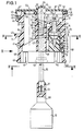
- FIG. 1 According to Figures 1, 2, 6 and 7 has an essentially cup-shaped plug housing 11 below radially outward distributed over the circumference several retaining lips 40 and above three concentric sealing rings 41, by means of which the plug housing inserted into a battery housing opening, not shown 11 tight and vertically fixed in this opening can.
- the plug housing 11 In the middle area the plug housing 11 is transverse provided on its central axis 65, flat cover plate 64, which is surrounded by an annular flange 42, which ensures that the Plug housing 11 only until the ring flange 42 strikes against one Mating surface of the battery housing, not shown, in the assigned Opening can be inserted.
- the lower edge region of the plug housing 11 can have axial slots 61 spring radially inward when inserted into a battery opening, causing the retaining lips 40 in a on the battery housing radially outside of the opening can snap into the intended complementary circumferential groove, which keeps the water refill plug securely on the battery case becomes.
- connection area located below the cover plate 64 60 of the plug housing 11 inserted into the battery opening, not shown is and establishes the connection with it, it is above the Cover plate 64 existing area of the plug housing 11 upwards.
- 5 6 and 8 open into the side of the plug housing in this area 11
- pipe socket 16, which is integral with the plug housing 11 are aligned with each other and into a flow channel connecting them 57 ( Figure 5) pass, which is also integrated in the plug housing 11 is and according to Figures 1, 2, 7 and 8 with respect to the central axis 65 of at least in the lower region essentially circular cylindrical Plug housing 11 is radially offset.
- the pipe socket 16 run perpendicular to the central axis 65.
- connection area 60 can also not be attached to one illustrated adapter be formed, which in turn tight in the Battery opening can be introduced.
- FIG. 1 branches off from the flow channel 57 in the middle at the bottom a connecting channel 17 that creates a flow connection from that according to Figures 1, 2, 3, 5 in a material projection 29 'on Edge of a much larger diameter, below open bore 18 with eccentric axis 67 parallel to the central axis 65 is provided and at a clear distance from the lower end of the bore 18 opens.
- the bore 18 goes into one of those described below Axial ribs 62 surrounding valve chamber 24 and provides one Water inlet for the latter.
- the bore 18 and the valve chamber 24th are arranged eccentrically to the central axis 65 and with respect to the parallel to the central axis 65 extending eccentric axis 67 substantially circular cylindrical educated.
- a stop pin is in the bore 18 from below 32 used with such a smaller diameter than the bore 18, that around the stop pin 32 a water absorption and - Passage space is present.
- the stop pin 32 has an annular flange 34, which is inserted into a matching recess 34 'and Bore 18 is sealed from below. With the adjacent housing parts 68 is the ring flange 34, for example by ultrasonic welding firmly and tightly connected.
- valve chamber 24 extends radially at the top inwardly projecting ring step 12, which has a water inlet opening (15) surrounds in a vertical bore 15 'with a reduced diameter, in which the valve rod 27 is arranged in the valve chamber 24
- Valve body 22 is vertically displaceable and arranged with play on all sides is.
- An O-ring 23 rests on the ring stage 12, which together with the ring stage 12 forms a valve seat 26 for the valve body 22 and has such a radial distance from the valve rod 27 that in between the water inlet opening 15 is present.
- the ring stage is preferred 12 formed on an O-ring receiving recess 70 which one has a significantly smaller diameter than the valve chamber 24, so that from this also a step-like transition into the O-ring receiving recess 70 is present.
- the O-ring receiving recess 70 dimensioned so that the O-ring 23 both in accommodates radial as well as in the axial direction.
- valve rod 27 occurs above the bore 15 'in the vertical distance from this by a guide sleeve 15 '' (Fig. 4) through into a water chamber 13 provided there.
- valve rod 27 At the upper end is the valve rod 27 in the vertical direction except for the manufacturing Tolerances positively connected to a cross piece 21, that extends radially to a central vertical receiving bore 43 and from its radially inner end there is a float rod 20 with all-round play 59 against the inner wall of the receiving bore 43 clearly below the lower edge of the plug housing 11 extends into the battery housing, not shown. Because of the game 59 between the float rod 20 and the wall the receiving bore 43 lies between the above the bore 15 ' existing water chamber 13 and the lower end of the plug housing 11 before a flow connection.
- the float rod 20 At the lower end is the float rod 20 with a coupling piece 33 provided, which in a recess 37 at the upper end of a rod-shaped Extension 58 of a float 19 engages.
- the length the float rod 20 is selected so that when in a battery opening used plug housing 11 and the correct electrolyte filling the Battery of float 19 dips just as far into the electrolyte, that it floats and over the float rod 20, the crosspiece 21 and the valve rod 27, the valve tappet 22 in that shown in Figure 2 Raises the closed position in which the valve body 22 on the O-ring 23 is tight.
- valve 14 ( Figure 1) forms the annular space between the valve seat 26 and the valve body 22 a water inlet opening 15 to the the vertical bore 15 'connects at the top.
- valve body 22 with the valve rod 27 should not be independent of the float 19 and the float rod 20 can move up and down.
- valve rod 27 is at the top provided with an upwardly tapering bevel 56, due to the fork 28 of the crosspiece 21 also from above onto the upper one End of the valve rod 27 can be snapped. That is why important because of the axial guidance of the valve rod 27 in the bore 15 'and the float rod 20 in the receiving bore 43 a lateral displacement of the two rods 20, 27 against each other despite the play in the holes only to a limited extent is possible.
- the flow channel 57 and the connecting channel 17 are according to the figures 1 to 3 through a wall piece 29 from the central receiving bore 43 tightly separated.
- a diagnostic opening 25 On the valve chamber 24 diametrically opposite side of the Stopper housing 11 is a diagnostic opening 25 with a parallel to Center axis 65 extending eccentric axis 30 provided axially passes from the outside in and through which to determine the Acid samples can be taken from the battery.
- valve chamber containing the valve body 22 24 located bore 18 is open below before assembly, so that from there both the O-ring 23 and the valve body 22 with the Valve rod 27 can be used. Then it is then in the Bore 18 inserted from below the stop pin 32 until it is in the ring arrangement penetrated by axial ribs 62 and the annular flange 34 is inserted tightly into the recess 34 'on the housing parts 68. Subsequently the ring flange 34 is, for example, by ultrasonic welding integral in the end position shown in Figures 1 and 2 connected to the plug housing 11.
- stop pin 32 is funnel-like downwardly tapered seat 35 on which the valve body 22 in the open position of the valve shown in FIG. 1 14 strikes.
- the funnel-shaped seat 35 goes into a coaxial to the eccentric axis 68 blind bore 36 over.
- the plug housing 11 is sealed at the top by a cover 53, at least in its central area made of transparent material should exist, so that one above the float rod 20 provided display dome 54 through the state of the upper end 38th the float rod 20 can be observed.
- the cover 53 closes both the water chamber 13 tightly from above as well as the diagnostic opening 25, for which purpose hollow cylindrical bottom cover 53 Projections 39, 52 are arranged such that they are tight in the upper ends of the diagnostic opening 25 or the circular cylindrical water chamber 13 intervene.
- the lid 53 is all around except in the area of one Hinge 46, 47, 48 with a lid edge protruding downwards 53 'provided.
- the cover 53 has a circular cylindrical shape Water chamber 13, the center 51 ( Figure 8) between the axes 65, 67 is a complementary hollow cylindrical projection 52 ( Figure 1, 2), with which the lid in the snapped state according to Figures 1 and 2 close to the top of the water chamber 13th is present.
- the plug housing 11, the cover 53, the valve body 22 with the valve rod 27, the crosspiece 21 with the float rod 20, the float 19 and the stop pin 32 separately, e.g. after the plastic injection molding process.
- the invention Water refill plug is therefore assembled from only five individual parts, to which then also the prefabricated float 19 and the O-ring 23 comes.
- a battery opening can be used, the float 19 more or less in the liquid electrolytes in the battery immersed.
- the water then flows vertically through the water flow chambers 69, 69 'or by the between the float rod 20 and the wall of the receiving bore 43 existing annulus 59 down into the battery case. Accordingly, the liquid electrolyte in the battery case filled with distilled water.
- Valve chamber 24 and the axial grooves 63 form a siphon-like Closure for gases which are closed with the refill plug Battery cell arise.
- valve chamber 24 extends from the valve chamber 24 downwards extending bore 18 and the connecting channel opening into this from above 17 achieves that in the valve chamber 24 and the axial grooves 63 an essentially bottom-up water flow is present. It is essential that the axial ribs 62 are down do not extend into the hole 18, so in the area of the hole 18 the liquid supplied through the connecting channel 17 itself can distribute evenly around the stop pin 32.
- a gas outlet opening 71 is provided on the side, covered by the lid edge 53 ', which adjoins a vertical gas duct 72 (FIG. 9) on the inside, which is connected to the inside of the battery below.
- the gas outlet opening 71 can also be at the top and / or bottom in one Depression of the peripheral wall of the plug housing 11 may be provided, to make splashing out more difficult.
- the housing which is inserted into an adapter, is below the Cover plate 64 formed so that it in the complementary adapter opening fits.
Landscapes
- Engineering & Computer Science (AREA)
- General Engineering & Computer Science (AREA)
- Mechanical Engineering (AREA)
- Chemical & Material Sciences (AREA)
- Chemical Kinetics & Catalysis (AREA)
- Electrochemistry (AREA)
- General Chemical & Material Sciences (AREA)
- Filling, Topping-Up Batteries (AREA)
Abstract
Description
- Figur 1
- eine teilweise vertikal geschnittene Seitenansicht eines erfindungsgemäßen Wassernachfüllstopfens bei geöffnetem Ventil,
- Figur 2
- eine analoge Schnittansicht bei weggelassener Schwimmerstange und weggelassenem Schwimmer im geschlossenen Zustand des Ventils,
- Figur 3
- eine schematische Schnittansicht nach Linie III-III in Figur 1,
- Figur 4
- einen schematischen Schnitt nach Linie IV-IV in Figur 3,
- Figur 5
- eine schematische Schnittansicht nach Linie V-V in Figur 3,
- Figur 6
- eine Seitenansicht des erfindungsgemäßen Wassernachfüllstopfens in Richtung des Pfeiles VI in Figur 1,
- Figur 7
- eine Seitenansicht des gleichen Gegenstandes aus einer um 90° um die Mittelachse 65 verschwenkten Richtung,
- Figur 8
- eine Draufsicht des erfindungsgemäßen Wassernachfüllstopfens vor Einbau des Ventilkörpers und des Querstückes, wobei der Deckel und die Schwimmerstange nur gestrichelt angedeutet sind,
- Figur 9
- eine teilweise geschnittene Ansicht des erfindungsgemäßen Wassernachfüllstopfens von unten nach Linie IX-IX in Figur 1.
- 11
- Stopfengehäuse
- 12
- Ringstufe
- 13
- Wasserkammer
- 14
- Ventil
- 15
- Wasserzulauföffnung
- 15'
- Bohrung
- 15''
- Führungsmanschette
- 16
- Rohrstutzen
- 17
- Verbindungskanal (Strömungsverbindung)
- 18
- Wassereinlaß
- 19
- Schwimmer
- 20
- Schwimmerstange
- 21
- Querstück
- 22
- Ventilkörper
- 23
- O-Ring
- 24
- Ventilkammer
- 25
- Diagnoseöffnung
- 26
- Ventilsitz
- 27
- Ventilstange
- 28
- Gabel
- 29
- Wandstück
- 29'
- Materialvorsprung
- 30
- Exzenterachse
- 31
- Nut
- 32
- Anschlagzapfen
- 33
- Kupplungsstück
- 34
- Ringflansch
- 34'
- Vertiefung
- 35
- Sitz
- 36
- Sackbohrung
- 37
- Ausnehmung
- 38
- oberes Ende der Schwimmerstange
- 39
- Vorsprung
- 40
- Halterlippe
- 41
- Dichtring
- 42
- Ringflansch
- 43
- Aufnahmebohrung
- 44
- Halterung
- 45
- Einsetzkanal
- 46
- Verrastung
- 47
- Zwischenglied
- 48
- Rastzapfen
- 49
- Hinterschneidung
- 50
- Rastvorsprung
- 51
- Mittelpunkt
- 52
- Vorsprung
- 53
- Deckel
- 53'
- Deckelrand
- 53''
- Handhabe
- 54
- Anzeigedom
- 55
- Kanalstück
- 56
- Abschrägung
- 57
- Durchflußkanal
- 58
- stangenförmige Verlängerung
- 59
- Spiel
- 60
- Verbindungsbereich
- 61
- Axialschlitz
- 62
- Axialrippen
- 63
- Axialnuten
- 64
- Deckplatte
- 65
- Mittelachse
- 66
- Diagnoseöffnung
- 67
- Exzenterachse
- 68
- Gehäuseteile
- 69
- Wasserdurchlaufkammer
- 69'
- Wasserdurchlaufkammer
- 69''
- Durchlauföffnung
- 69'''
- Zwischenboden
- 70
- O-Ring-Aufnahmevertiefung
- 71
- Gasaustrittsöffnung
- 71'
- Kanalwand
- 71''
- Kanalwandstück
- 72
- Gasleitkanal
Claims (23)
- Wassernachfüllstopfen für einen flüssigen Elektrolyten enthaltende Batterien mit einem Stopfengehäuse (11), welches im unteren Bereich außen entweder komplementär zu einer oberen Batteriegehäuseöffnung oder einem Adapter ausgebildet ist, der seinerseits komplementär zu einer oberen Batteriegehäuseöffnung gestaltet ist, mit einer oben am Stopfengehäuse (11) angeordneten, nach außen abgeschlossenen, vorzugsweise kreiszylindrischen und/oder oben einen insbesondere abnehmbaren Deckel (53) aufweisenden Wasserkammer (13), welche an eine durch ein aus einem Ventilkörper (22) und einem Ventilsitz (26) bestehendes, einen vorzugsweise als Bohrung ausgebildeten Wassereinlaß (18) besitzendes Ventil (14) verschließbare Wasserzulauföffnung (15) angeschlossen ist und wenigstens eine Strömungsverbindung (59, 69, 69') mit demjenigen Bereich des Stopfengehäuses (11) aufweist, der nach dem Einsetzen in eine Batteriegehäuseöffnung mit dem Innenraum der Batterie in Strömungsverbindung steht, mit wenigstens einem am Stopfengehäuse (11) angeordneten Rohrstutzen (16), an den ein Wasserzuführschlauch ansetzbar ist und welcher in Strömungsverbindung (17) mit dem Wassereinlaß (18) steht, mit einem sich durch eine vorzugsweise zentrale Aufnahmebohrung (43) des Stopfengehäuses (11) erstreckenden, unten aus dem Stopfengehäuse (11) herausragenden Schwimmer (19), der über eine Schwimmerstange (20) und ein an derem oberen Ende vorgesehenes Querstück (21) sowie vorzugsweise eine Ventilstange (27) mit dem Ventilkörper (22) verbunden ist,
dadurch gekennzeichnet,
daß der Ventilsitz (26) und die Wasserzulauföffnung (15) an bzw. in einem Teil des Stopfengehäuses (11) ausgebildet sind, d.h. einen integrierenden Bestandteil des Stopfengehäuses (11) bilden. - Wassernachfüllstopfen nach Anspruch 1,
dadurch gekennzeichnet,
daß im Stopfengehäuse (11) eine einseitig, vorzugsweise oben durch den Ventilsitz (26) begrenzte Ventilkammer (24) ausgebildet ist, in der der Ventilkörper (22) auf den Ventilsitz (26) zu bzw. von ihm beweglich und vorzugsweise geführt angeordnet ist. - Wassernachfüllstopfen nach Anspruch 1 oder 2,
dadurch gekennzeichnet,
daß sich vom Ventilkörper (22) eine Ventilstange (27) durch eine vorzugsweise oben an die Ventilkammer (24) anschließende Bohrung (15') im Stopfengehäuse (11) zum Querstück (21) erstreckt. - Wassernachfüllstopfen nach Anspruch 3,
dadurch gekennzeichnet,
daß die Bohrung (15') einen größeren Durchmesser als die Ventilstange (27) aufweist, so daß rund um die Ventilstange (27) ein Ringraum vorgesehen ist, der einen an die Wasserzulauföffnung (15) anschließenden Wasserzulaufkanal bildet, und/oder daß rund um die Durchführungsbohrung (15') für die Ventilstange (27) und/oder darüber ein oder mehrere Kanalstücke (55) angeordnet sind, die zur Wasserkammer (13) hin offen sind bzw. einen Bestandteil derselben bilden. - Wassernachfüllstopfen nach einem der vorhergehenden Ansprüche,
dadurch gekennzeichnet,
daß der diskusartig ausgebildete Ventilkörper (22) rundum von sich in Bewegungsrichtung des Ventilkörpers (22) erstreckenden Axialrippen (62) und dazwischen befindlichen Axialnuten (63) umgeben ist, die vorzugsweise radial außen unmittelbar an das Stopfengehäuse (11) angrenzen. - Wassernachfüllstopfen nach Anspruch 5,
dadurch gekennzeichnet,
daß der Wassereinlaß (18) des Ventils (14) als unterhalb der Ventilkammer (24) und ggf. der Axialrippen (62) angeordnete Bohrung (18) ausgebildet ist, in welche vorzugsweise in deutlichem Abstand von der Ventilkammer (24) die Strömungsverbindung (17) insbesondere am Rand mündet und welche bevorzugt durch einen von unten eingesteckten Anschlagzapfen (32) mit geringerem Durchmesser als die Bohrung (18) unten dicht verschlossen ist. - Wassernachfüllstopfen nach einem der vorhergehenden Ansprüche,
dadurch gekennzeichnet,
daß die Ventilkammer (24) derart dimensioniert ist, daß vor Einbringen des Anschlagzapfens (32) der Ventilkörper (22) ggf. mit O-Ring (23) montiert werden kann. - Wassernachfüllstopfen nach Anspruch 7,
dadurch gekennzeichnet,
daß der Anschlagzapfen (32) vorzugsweise oben einen insbesondere trichterförmigen Sitz (35) für den sich in Offenstellung befindlichen Ventilkörper (22) aufweist. - Wassernachfüllstopfen nach einem der vorhergehenden Ansprüche,
dadurch gekennzeichnet,
daß die Ventilkammer (24) und die vorzugsweise mit ihr konzentrische Bohrung (18) exzentrisch im kreisförmigen Stopfengehäuse (11) angeordnet ist und einen vorzugsweise um mehr als die Hälfte geringeren Durchmesser als das Stopfengehäuse (11) aufweist. - Wassernachfüllstopfen nach einem der vorhergehenden Ansprüche,
dadurch gekennzeichnet,
daß die Aufnahmebohrung (43) für die Schwimmerstange (20) vorzugsweise zumindest im wesentlichen zentral und koaxial im Stopfengehäuse (11) angeordnet ist. - Wassernachfüllstopfen nach Anspruch 9 oder 10,
dadurch gekennzeichnet,
daß diametral gegenüber der Ventilkammer (24) eine von außen nach innen durchgehende axiale Diagnoseöffnung (25) vorgesehen ist, durch welche Säure zur Feststellung des Ladezustandes entnommen werden kann. - Wassernachfüllstopfen nach Anspruch 11,
dadurch gekennzeichnet,
daß die Diagnoseöffnung (25) und die Wasserkammer (13) durch einen gemeinsamen abnehmbaren Deckel (53) von außen dicht verschlossen sind. - Wassernachfüllstopfen nach einem der vorhergehenden Ansprüche,
dadurch gekennzeichnet,
daß der bzw. die Rohrstutzen (16) einstückig mit dem Stopfengehäuse (11) ausgebildet ist bzw. sind und vorzugsweise senkrecht zur Mittelachse (65) des Stopfengehäuses (11) verlaufen. - Wassernachfüllstopfen nach Anspruch 13,
dadurch gekennzeichnet,
daß ein und vorzugsweise zwei entgegengesetzt gerichtete Rohrstutzen (16) radial zwischen der Ventilkammer (24) und der Schwimmstangen-Aufnahmebohrung (43) sowie axial oberhalb der Ventilkammer (24) vorzugsweise seitlich der Ventilstange (27) vorgesehen sind. - Wassernachfüllstopfen nach Anspruch 14,
dadurch gekennzeichnet,
daß die Rohrstutzen (16) in einen mit ihnen fluchtenden, im Stopfengehäuse (11) vorgesehenen Durchflußkanal (57) übergehen, von dem vorzugsweise in der Mitte und insbesondere senkrecht ein Verbindungskanal (17) abzweigt, der in einem seitlichen Materialvorsprung (29') am Rande der Bohrung (18) vorgesehen ist und sich nach unten vorzugsweise bis in den Ringraum zwischen den Außenwänden der Bohrung (18) und des Anschlagzapfens (32) erstreckt, derart, daß das Wasser durch den Verbindungskanal (17) in den betreffenden Ringraum strömt und von dort nach oben in die Ventilkammer (24) und die Axialnuten (63) gelangen kann. - Wassernachfüllstopfen nach einem der vorhergehenden Ansprüche,
dadurch gekennzeichnet,
daß das Stopfengehäuse (11) eine oberhalb des kreiszylindrischen Verbindungsbereiches (60) eine Deckplatte (64) aufweist, an der einstückig sich nach oben und unten erstreckend die Gehäuseteile der Ventilkammer (24), der Ventilstangen-Aufnahmebohrung (43) und der Diagnoseöffnung (25) vorgesehen sind. - Wassernachfüllstopfen nach einem der vorhergehenden Ansprüche,
dadurch gekennzeichnet,
daß außerhalb der Aufnahmebohrung (43) für die Schwimmerstange (20) ein oder mehrere Wasserdurchlaufkammern (69, 69') vorgesehen sind, die oben mit der Wasserkammer (13) und unten mit demjenigen Bereich des Stopfengehäuses (11) in Strömungsverbindung stehen, welcher an den Innenraum der Batteriezelle anschließt, die mit dem Wassernachfüllstopfen verschlossen ist, und/oder daß das Kanalstück (55) bzw. die Kanalstücke (55), die innen mit der Durchführungsbohrung (15') in Verbindung stehen, seitlich in eine bzw. mehrere Wasserdurchlaufkammern (69') übergehen, deren unteres Ende mit der zugeordneten Batteriezelle im Strömungsverbindung steht, wobei vorzugsweise die Wasserdurchlaufkammer in einen oberen und einen dagegen versetzten unteren Teil unterteilt ist, und die beiden Teile durch eine an einem Zwischenboden (69''') gebildeten Öffnung (69'') miteinander verbunden sind. - Wassernachfüllstopfen für einen flüssigen Elektrolyten enthaltende Batterien mit einem Stopfengehäuse (11), welches im unteren Bereich außen entweder komplementär zu einer oberen Batteriegehäuseöffnung oder einem Adapter ausgebildet ist, der seinerseits komplementär zu einer oberen Batteriegehäuseöffnung gestaltet ist, mit einer oben am Stopfengehäuse (11) angeordneten, nach außen abgeschlossenen, vorzugsweise kreiszylindrischen und/oder oben einen insbesondere abnehmbaren Deckel (53) aufweisenden Wasserkammer (13), welche an eine durch ein aus einem Ventilkörper (22) und einem Ventilsitz (26) bestehendes, einen Wassereinlaß (18) besitzendes Ventil (14) verschließbare Wasserzulauföffnung (15) angeschlossen ist und wenigstens eine Strömungsverbindung (59, 69) mit demjenigen Bereich des Stopfengehäuses (11) aufweist der nach dem Einsetzen in eine Batteriegehäuseöffnung mit dem Innenraum der Batterie in Strömungsverbindung steht, mit wenigstens einem am Stopfengehäuse (11) angeordneten Rohrstutzen (16), an den ein Wasserzuführschlauch ansetzbar ist und welcher in Strömungsverbindung (17) mit dem Wassereinlaß (18) steht, mit einem sich durch eine vorzugsweise zentrale Aufnahmebohrung (43) des Stopfengehäuses (11) erstreckenden, unten aus dem Stopfengehäuse (11) herausragenden Schwimmer (19), der über eine Schwimmerstange (20) und ein an derem oberen Ende vorgesehenes Querstück (21) sowie vorzugsweise eine Ventilstange (27) mit dem Ventilkörper (22) verbunden ist, insbesondere nach einem der vorhergehenden Ansprüche,
dadurch gekennzeichnet,
daß die Seitenwände der Ventilkammer (24) durch Teile des Stopfengehäuses (11) gebildet sind, d.h. einen integrierenden Bestandteil des Stopfengehäuses (11) bilden, und die gegebenenfalls vorgesehenen Axialrippen (62) ebenfalls einen integrierenden Bestandteil des Stopfengehäuses (11) bilden. - Wassernachfüllstopfen nach einem der vorhergehenden Ansprüche,
dadurch gekennzeichnet,
daß die Axialrippen (62) sich axial bis in die Höhe des Ventilsitzes (26) erstrecken. - Wassernachfüllstopfen nach einem der vorhergehenden Ansprüche,
dadurch gekennzeichnet,
daß axial zwischen der Ventilkammer (24) und der Ventilstangen-Bohrung (15') eine O-Ring-Aufnahmevertiefung (70) mit kleinerem Durchmesser als die Ventilkammer (24) und größerem Durchmesser als die Bohrung (15') vorgesehen ist. - Wassernachfüllstopfen nach Anspruch 20,
dadurch gekennzeichnet,
daß die gegebenenfalls vorhandenen Axialrippen (62) sich radial nach innen bis kurz vor den oder allenfalls bis zum radial äußeren Rand der O-Ring-Aufnahmevertiefung (70) erstrecken. - Wassernachfüllstopfen nach einem der vorhergehenden Ansprüche,
dadurch gekennzeichnet,
daß in dem oberhalb der Deckplatte (64) liegenden Bereich der Seitenwand des Stopfengehäuses (11) eine oder mehrere Gasaustrittsöffnungen (71) vorgesehen sind, die mit dem zum Batterie-Inneren führenden unteren Hohlraum des Stopfengehäuses (11) in Verbindung steht bzw. stehen, wobei insbesondere der Deckel (53) einen nach unten gerichteten Deckelrand (53') aufweist, der die Gasaustrittsöffnung(en) (71) zumindest teilweise mit Abstand abdeckt. - Wassernachfüllstopfen nach Anspruch 22,
dadurch gekennzeichnet,
daß die Gasaustrittsöffnung (71) innen an einen vorzugsweise vertikalen Gasleitkanal (72) angrenzt, der die Verbindung zum unteren Hohlraum herstellt, wobei bevorzugt eine vertikale Kanalwand (71') und/oder ein vertikales Kanalwandstück (71'') den Gasleitkanal (72) zumindest im wesentlichen auf die Größe der Gasaustrittsöffnung(en) (71) einengen und insbesondere nach unten bis in den Hohlraum verlängern, und zwar zweckmäßigerweise bis zum unteren Rand der Diagnoseöffnung (25).
Applications Claiming Priority (3)
| Application Number | Priority Date | Filing Date | Title |
|---|---|---|---|
| DE1996147151 DE19647151A1 (de) | 1996-11-14 | 1996-11-14 | Wassernachfüllstopfen für einen flüssigen Elektrolyten enthaltende Batterien |
| DE19647151 | 1996-11-14 | ||
| CA 2233818 CA2233818C (en) | 1996-11-14 | 1998-04-02 | Water top-up plug for batteries containing a liquid electrolyte |
Publications (2)
| Publication Number | Publication Date |
|---|---|
| EP0843370A1 true EP0843370A1 (de) | 1998-05-20 |
| EP0843370B1 EP0843370B1 (de) | 2001-10-04 |
Family
ID=31496457
Family Applications (1)
| Application Number | Title | Priority Date | Filing Date |
|---|---|---|---|
| EP19970119743 Expired - Lifetime EP0843370B1 (de) | 1996-11-14 | 1997-11-11 | Wassernachfüllstopfen für einen flüssigen Elektrolyten enthaltende Batterien |
Country Status (6)
| Country | Link |
|---|---|
| US (1) | US5902694A (de) |
| EP (1) | EP0843370B1 (de) |
| AT (1) | ATE206560T1 (de) |
| CA (1) | CA2233818C (de) |
| DE (2) | DE19647151A1 (de) |
| PT (1) | PT843370E (de) |
Cited By (1)
| Publication number | Priority date | Publication date | Assignee | Title |
|---|---|---|---|---|
| EP2133940A1 (de) * | 2008-06-12 | 2009-12-16 | TABA S.r.l. | Belüftungsstecker für Stationärbatterien mit Strahlungswiderstandsschutz sowie System zur unbegrenzten automatischen Aufsetzung und Aufsetzbaugruppe mit besagtem Stecker |
Families Citing this family (11)
| Publication number | Priority date | Publication date | Assignee | Title |
|---|---|---|---|---|
| US6248138B1 (en) * | 1999-06-09 | 2001-06-19 | Delphi Technologies, Inc. | Activation and sealing of storage batteries |
| US6227229B1 (en) | 2000-02-08 | 2001-05-08 | Flow-Rite Controls, Ltd. | High gain fluid control valve assembly |
| US6718996B2 (en) * | 2000-04-10 | 2004-04-13 | Club Car, Inc. | Filling pod for a battery, vehicle and method of supplying fluid to a battery |
| US6622744B2 (en) | 2000-04-10 | 2003-09-23 | Club Car, Inc. | Filling pod for a battery, vehicle and method of supplying fluid to a battery |
| US6786226B2 (en) * | 2000-04-10 | 2004-09-07 | Club Car, Inc. | Battery fluid supply system |
| US20080020269A1 (en) * | 2006-07-18 | 2008-01-24 | Elke Oschmann | Filling plug for battery cells |
| DE102009038915B4 (de) * | 2009-08-26 | 2020-08-13 | FRÖTEK Vermögensverwaltung GmbH | Wassernachfüllstopfen |
| DE102009038999A1 (de) * | 2009-08-28 | 2011-03-03 | FRÖTEK Vermögensverwaltung GmbH | Wassernachfüllstopfen |
| US20110111274A1 (en) * | 2009-11-06 | 2011-05-12 | Thomas Foushee | Flooded Battery Vent Cap |
| US8715843B2 (en) * | 2010-02-17 | 2014-05-06 | Doyle Manufacturing, Inc. | Vent cap including watering valve, float and fluid flow path that does not impinge float |
| CN103748706B (zh) * | 2011-11-17 | 2016-09-21 | 株式会社杰士汤浅国际 | 蓄电池用补水栓 |
Citations (5)
| Publication number | Priority date | Publication date | Assignee | Title |
|---|---|---|---|---|
| EP0207346A2 (de) * | 1985-07-03 | 1987-01-07 | LA BATTERIA di M. TADIELLO S.r.l. | Stopfen für Zellen von elektrischen Speicherbatterien |
| EP0234278A1 (de) * | 1986-01-29 | 1987-09-02 | Olimpio Stocchiero | Stopfen mit automatischer Einfüllvorrichtung für Akkumulator-Elemente |
| JPS64644A (en) * | 1986-09-22 | 1989-01-05 | Shin Kobe Electric Mach Co Ltd | Electrolyte pouring device for storage battery |
| DE3725976A1 (de) * | 1987-08-05 | 1989-02-16 | Willy Herrmann | Speisevorrichtung fuer akkumulatorenbatterien |
| WO1991017577A1 (de) * | 1990-05-02 | 1991-11-14 | Daniel Rover | Schwimmerventil für füllanlagen, insbesondere zum füllen von elektrischen traktionsbatterien |
Family Cites Families (6)
| Publication number | Priority date | Publication date | Assignee | Title |
|---|---|---|---|---|
| DE2708531C3 (de) * | 1975-08-26 | 1981-09-24 | Daimler-Benz Ag, 7000 Stuttgart | Einfüll- und Kontrollvorrichtung für eine Batterie |
| DE2822927C2 (de) * | 1978-05-26 | 1986-06-05 | Daimler-Benz Ag, 7000 Stuttgart | Batterie |
| US4386141A (en) * | 1982-02-22 | 1983-05-31 | Exide Corporation | Watering device for batteries |
| US4749633A (en) * | 1987-10-13 | 1988-06-07 | Elias Leonard W | Battery watering device |
| IT229781Y1 (it) * | 1993-04-06 | 1999-02-05 | Taba Srl | Dispositivo a galleggiante perfezionato per il controllo del livello dell'acqua distillata in batterie elettriche |
| DE19511803A1 (de) * | 1995-03-30 | 1996-10-02 | Elke Oschmann | Füllvorrichtung für Batteriezellen |
-
1996
- 1996-11-14 DE DE1996147151 patent/DE19647151A1/de not_active Withdrawn
-
1997
- 1997-11-11 AT AT97119743T patent/ATE206560T1/de not_active IP Right Cessation
- 1997-11-11 DE DE59704772T patent/DE59704772D1/de not_active Expired - Lifetime
- 1997-11-11 EP EP19970119743 patent/EP0843370B1/de not_active Expired - Lifetime
- 1997-11-11 PT PT97119743T patent/PT843370E/pt unknown
- 1997-11-13 US US08/969,998 patent/US5902694A/en not_active Expired - Lifetime
-
1998
- 1998-04-02 CA CA 2233818 patent/CA2233818C/en not_active Expired - Fee Related
Patent Citations (5)
| Publication number | Priority date | Publication date | Assignee | Title |
|---|---|---|---|---|
| EP0207346A2 (de) * | 1985-07-03 | 1987-01-07 | LA BATTERIA di M. TADIELLO S.r.l. | Stopfen für Zellen von elektrischen Speicherbatterien |
| EP0234278A1 (de) * | 1986-01-29 | 1987-09-02 | Olimpio Stocchiero | Stopfen mit automatischer Einfüllvorrichtung für Akkumulator-Elemente |
| JPS64644A (en) * | 1986-09-22 | 1989-01-05 | Shin Kobe Electric Mach Co Ltd | Electrolyte pouring device for storage battery |
| DE3725976A1 (de) * | 1987-08-05 | 1989-02-16 | Willy Herrmann | Speisevorrichtung fuer akkumulatorenbatterien |
| WO1991017577A1 (de) * | 1990-05-02 | 1991-11-14 | Daniel Rover | Schwimmerventil für füllanlagen, insbesondere zum füllen von elektrischen traktionsbatterien |
Non-Patent Citations (1)
| Title |
|---|
| PATENT ABSTRACTS OF JAPAN vol. 013, no. 166 (E - 746) 20 April 1989 (1989-04-20) * |
Cited By (1)
| Publication number | Priority date | Publication date | Assignee | Title |
|---|---|---|---|---|
| EP2133940A1 (de) * | 2008-06-12 | 2009-12-16 | TABA S.r.l. | Belüftungsstecker für Stationärbatterien mit Strahlungswiderstandsschutz sowie System zur unbegrenzten automatischen Aufsetzung und Aufsetzbaugruppe mit besagtem Stecker |
Also Published As
| Publication number | Publication date |
|---|---|
| DE19647151A1 (de) | 1998-06-25 |
| CA2233818A1 (en) | 1999-10-02 |
| PT843370E (pt) | 2002-03-28 |
| EP0843370B1 (de) | 2001-10-04 |
| ATE206560T1 (de) | 2001-10-15 |
| CA2233818C (en) | 2007-03-06 |
| US5902694A (en) | 1999-05-11 |
| DE59704772D1 (de) | 2001-11-08 |
Similar Documents
| Publication | Publication Date | Title |
|---|---|---|
| EP1793933B1 (de) | Verwendung eines fliessbechers für eine farbspritzpistole | |
| DE102004007733B4 (de) | Fließbecher für eine Farbspritzpistole | |
| DE3242945C2 (de) | Ventilanordnung | |
| DE3007702C2 (de) | ||
| EP0843370B1 (de) | Wassernachfüllstopfen für einen flüssigen Elektrolyten enthaltende Batterien | |
| DE2936673A1 (de) | Entlueftungsventil | |
| DE102004003438A1 (de) | Fließbecher für eine Farbspritzpistole | |
| DE4408888A1 (de) | Filter für eine Brennkraftmaschine | |
| DE2941244A1 (de) | Rueckschlagventil | |
| DE4014103A1 (de) | Schwimmerventil fuer fuellanlagen, insbesondere zum fuellen von elektrischen traktionsbatterien | |
| EP0763262B1 (de) | Füllvorrichtung für batteriezellen mit einem schwimmer-betätigten ventil | |
| DE2037938A1 (de) | Entluftungs und Full Vorrichtung fur Akkumulatoren | |
| DE19827992A1 (de) | Vorrichtung zum Verbinden einer Volumenstrom-Messeinrichtung mit einer flüssigkeitsführenden Rohrleitung | |
| EP3204669B1 (de) | Ablaufstutzen | |
| DE3127619A1 (de) | Automatische einfuellvorrichtung fuer batteriezellen | |
| DE102005021957A1 (de) | Filter, insbesondere Kühlwasserfilter einer Brennkraftmschine | |
| DE1671833A1 (de) | Fuell- und Belueftungsvorrichtung fuer Batterien | |
| EP0756341B1 (de) | Wassernachfüllstopfen für einen flüssigen Elektrolyten enthaltende Batterien | |
| EP1097635B1 (de) | Vorrichtung zum Ausgleich des Drucks einer Flüssigkeit und Verfahren zur Änderung des Druckausgleichsverhältnisses | |
| DE3545977A1 (de) | Buerstenartiges schreibinstrument | |
| DE19807664A1 (de) | Schwimmerventil für ein Sauggerät | |
| EP0061164B1 (de) | Rohrförmige Dosiereinrichtung zur Abgabe von Flüssigkeitsmengen gleichen Volumens | |
| DE2853513A1 (de) | Vergaser- und reguliervorrichtung fuer gasfeuerzeuge | |
| DE19705181B4 (de) | Bügeleisen mit Wassertank | |
| DE4315700A1 (de) | Belüftungseinrichtung |
Legal Events
| Date | Code | Title | Description |
|---|---|---|---|
| PUAI | Public reference made under article 153(3) epc to a published international application that has entered the european phase |
Free format text: ORIGINAL CODE: 0009012 |
|
| AK | Designated contracting states |
Kind code of ref document: A1 Designated state(s): AT BE CH DE DK ES FI FR GB GR IT LI LU NL PT SE |
|
| AX | Request for extension of the european patent |
Free format text: AL;LT;LV;MK;RO;SI |
|
| 17P | Request for examination filed |
Effective date: 19980617 |
|
| AKX | Designation fees paid |
Free format text: AT BE CH DE DK ES FI FR GB GR IT LI LU NL PT SE |
|
| RBV | Designated contracting states (corrected) |
Designated state(s): AT BE CH DE DK ES FI FR GB GR IT LI LU NL PT SE |
|
| 17Q | First examination report despatched |
Effective date: 19990930 |
|
| GRAG | Despatch of communication of intention to grant |
Free format text: ORIGINAL CODE: EPIDOS AGRA |
|
| GRAG | Despatch of communication of intention to grant |
Free format text: ORIGINAL CODE: EPIDOS AGRA |
|
| GRAG | Despatch of communication of intention to grant |
Free format text: ORIGINAL CODE: EPIDOS AGRA |
|
| GRAH | Despatch of communication of intention to grant a patent |
Free format text: ORIGINAL CODE: EPIDOS IGRA |
|
| GRAH | Despatch of communication of intention to grant a patent |
Free format text: ORIGINAL CODE: EPIDOS IGRA |
|
| GRAA | (expected) grant |
Free format text: ORIGINAL CODE: 0009210 |
|
| AK | Designated contracting states |
Kind code of ref document: B1 Designated state(s): AT BE CH DE DK ES FI FR GB GR IT LI LU NL PT SE |
|
| PG25 | Lapsed in a contracting state [announced via postgrant information from national office to epo] |
Ref country code: GB Free format text: LAPSE BECAUSE OF FAILURE TO SUBMIT A TRANSLATION OF THE DESCRIPTION OR TO PAY THE FEE WITHIN THE PRESCRIBED TIME-LIMIT Effective date: 20011004 Ref country code: FI Free format text: LAPSE BECAUSE OF FAILURE TO SUBMIT A TRANSLATION OF THE DESCRIPTION OR TO PAY THE FEE WITHIN THE PRESCRIBED TIME-LIMIT Effective date: 20011004 |
|
| REF | Corresponds to: |
Ref document number: 206560 Country of ref document: AT Date of ref document: 20011015 Kind code of ref document: T |
|
| REG | Reference to a national code |
Ref country code: CH Ref legal event code: EP |
|
| REF | Corresponds to: |
Ref document number: 59704772 Country of ref document: DE Date of ref document: 20011108 |
|
| PG25 | Lapsed in a contracting state [announced via postgrant information from national office to epo] |
Ref country code: SE Free format text: LAPSE BECAUSE OF FAILURE TO SUBMIT A TRANSLATION OF THE DESCRIPTION OR TO PAY THE FEE WITHIN THE PRESCRIBED TIME-LIMIT Effective date: 20020104 Ref country code: DK Free format text: LAPSE BECAUSE OF FAILURE TO SUBMIT A TRANSLATION OF THE DESCRIPTION OR TO PAY THE FEE WITHIN THE PRESCRIBED TIME-LIMIT Effective date: 20020104 |
|
| PG25 | Lapsed in a contracting state [announced via postgrant information from national office to epo] |
Ref country code: GR Free format text: LAPSE BECAUSE OF FAILURE TO SUBMIT A TRANSLATION OF THE DESCRIPTION OR TO PAY THE FEE WITHIN THE PRESCRIBED TIME-LIMIT Effective date: 20020105 |
|
| ET | Fr: translation filed | ||
| REG | Reference to a national code |
Ref country code: PT Ref legal event code: SC4A Free format text: AVAILABILITY OF NATIONAL TRANSLATION Effective date: 20020103 |
|
| GBV | Gb: ep patent (uk) treated as always having been void in accordance with gb section 77(7)/1977 [no translation filed] |
Effective date: 20011004 |
|
| PG25 | Lapsed in a contracting state [announced via postgrant information from national office to epo] |
Ref country code: ES Free format text: LAPSE BECAUSE OF FAILURE TO SUBMIT A TRANSLATION OF THE DESCRIPTION OR TO PAY THE FEE WITHIN THE PRESCRIBED TIME-LIMIT Effective date: 20020430 |
|
| PLBE | No opposition filed within time limit |
Free format text: ORIGINAL CODE: 0009261 |
|
| STAA | Information on the status of an ep patent application or granted ep patent |
Free format text: STATUS: NO OPPOSITION FILED WITHIN TIME LIMIT |
|
| 26N | No opposition filed | ||
| PGFP | Annual fee paid to national office [announced via postgrant information from national office to epo] |
Ref country code: PT Payment date: 20061107 Year of fee payment: 10 |
|
| PGFP | Annual fee paid to national office [announced via postgrant information from national office to epo] |
Ref country code: LU Payment date: 20061124 Year of fee payment: 10 |
|
| REG | Reference to a national code |
Ref country code: PT Ref legal event code: MM4A Free format text: LAPSE DUE TO NON-PAYMENT OF FEES Effective date: 20080512 |
|
| PG25 | Lapsed in a contracting state [announced via postgrant information from national office to epo] |
Ref country code: PT Free format text: LAPSE BECAUSE OF NON-PAYMENT OF DUE FEES Effective date: 20080512 |
|
| PG25 | Lapsed in a contracting state [announced via postgrant information from national office to epo] |
Ref country code: LU Free format text: LAPSE BECAUSE OF NON-PAYMENT OF DUE FEES Effective date: 20071111 |
|
| PGFP | Annual fee paid to national office [announced via postgrant information from national office to epo] |
Ref country code: CH Payment date: 20091019 Year of fee payment: 13 Ref country code: AT Payment date: 20091016 Year of fee payment: 13 |
|
| PGFP | Annual fee paid to national office [announced via postgrant information from national office to epo] |
Ref country code: NL Payment date: 20091123 Year of fee payment: 13 |
|
| PGFP | Annual fee paid to national office [announced via postgrant information from national office to epo] |
Ref country code: BE Payment date: 20091123 Year of fee payment: 13 |
|
| PGFP | Annual fee paid to national office [announced via postgrant information from national office to epo] |
Ref country code: IT Payment date: 20101126 Year of fee payment: 14 |
|
| BERE | Be: lapsed |
Owner name: *LANDAU REINHARD Effective date: 20101130 |
|
| REG | Reference to a national code |
Ref country code: NL Ref legal event code: V1 Effective date: 20110601 |
|
| REG | Reference to a national code |
Ref country code: CH Ref legal event code: PL |
|
| PG25 | Lapsed in a contracting state [announced via postgrant information from national office to epo] |
Ref country code: CH Free format text: LAPSE BECAUSE OF NON-PAYMENT OF DUE FEES Effective date: 20101130 Ref country code: LI Free format text: LAPSE BECAUSE OF NON-PAYMENT OF DUE FEES Effective date: 20101130 |
|
| PG25 | Lapsed in a contracting state [announced via postgrant information from national office to epo] |
Ref country code: BE Free format text: LAPSE BECAUSE OF NON-PAYMENT OF DUE FEES Effective date: 20101130 Ref country code: AT Free format text: LAPSE BECAUSE OF NON-PAYMENT OF DUE FEES Effective date: 20101111 Ref country code: NL Free format text: LAPSE BECAUSE OF NON-PAYMENT OF DUE FEES Effective date: 20110601 |
|
| PGFP | Annual fee paid to national office [announced via postgrant information from national office to epo] |
Ref country code: FR Payment date: 20111125 Year of fee payment: 15 |
|
| PGFP | Annual fee paid to national office [announced via postgrant information from national office to epo] |
Ref country code: DE Payment date: 20120126 Year of fee payment: 15 |
|
| REG | Reference to a national code |
Ref country code: FR Ref legal event code: ST Effective date: 20130731 |
|
| PG25 | Lapsed in a contracting state [announced via postgrant information from national office to epo] |
Ref country code: IT Free format text: LAPSE BECAUSE OF NON-PAYMENT OF DUE FEES Effective date: 20121111 |
|
| REG | Reference to a national code |
Ref country code: DE Ref legal event code: R119 Ref document number: 59704772 Country of ref document: DE Effective date: 20130601 |
|
| PG25 | Lapsed in a contracting state [announced via postgrant information from national office to epo] |
Ref country code: DE Free format text: LAPSE BECAUSE OF NON-PAYMENT OF DUE FEES Effective date: 20130601 |
|
| PG25 | Lapsed in a contracting state [announced via postgrant information from national office to epo] |
Ref country code: FR Free format text: LAPSE BECAUSE OF NON-PAYMENT OF DUE FEES Effective date: 20121130 |