EP0842802B1 - Door with sliding glass, especially for motor vehicle - Google Patents
Door with sliding glass, especially for motor vehicle Download PDFInfo
- Publication number
- EP0842802B1 EP0842802B1 EP19970402736 EP97402736A EP0842802B1 EP 0842802 B1 EP0842802 B1 EP 0842802B1 EP 19970402736 EP19970402736 EP 19970402736 EP 97402736 A EP97402736 A EP 97402736A EP 0842802 B1 EP0842802 B1 EP 0842802B1
- Authority
- EP
- European Patent Office
- Prior art keywords
- window
- door
- guide means
- door according
- gripping members
- Prior art date
- Legal status (The legal status is an assumption and is not a legal conclusion. Google has not performed a legal analysis and makes no representation as to the accuracy of the status listed.)
- Expired - Lifetime
Links
Images


Classifications
-
- B—PERFORMING OPERATIONS; TRANSPORTING
- B60—VEHICLES IN GENERAL
- B60J—WINDOWS, WINDSCREENS, NON-FIXED ROOFS, DOORS, OR SIMILAR DEVICES FOR VEHICLES; REMOVABLE EXTERNAL PROTECTIVE COVERINGS SPECIALLY ADAPTED FOR VEHICLES
- B60J1/00—Windows; Windscreens; Accessories therefor
- B60J1/08—Windows; Windscreens; Accessories therefor arranged at vehicle sides
- B60J1/12—Windows; Windscreens; Accessories therefor arranged at vehicle sides adjustable
- B60J1/16—Windows; Windscreens; Accessories therefor arranged at vehicle sides adjustable slidable
- B60J1/17—Windows; Windscreens; Accessories therefor arranged at vehicle sides adjustable slidable vertically
Definitions
- the present invention relates to a glass door sliding, in particular for a motor vehicle.
- a door in particular for a motor vehicle, of the type comprising a sliding glass in the door between two positions high and low, the window comprising an edge substantially parallel to the sliding direction of the glass intended for cooperate with guide means carried by the door.
- FR-A-2 705 391 describes a door for a vehicle automobile of the aforementioned type.
- the glass of this door has two front and rear edges cooperating with two slides fixed front and rear.
- the door also has a member wedging intended to cooperate with the window when the latter is in the high position.
- the glass guide means described in this document are specific to the shape of the door. These means guides cannot therefore be adapted to shapes various door.
- the guide means include, for each front edge or rear of the glass, at least two U-shaped elements arranged one above each other. These elements, in fact constituting slides, cooperate with play with the window. So the U-shaped elements allow movement of the glass between their branches necessary to account for the tolerances of ratings.
- the object of the invention is to propose means of guiding of a glass adaptable on shaped doors varied, making it possible to avoid, in particular, the clicking of the glass against other elements housed in the door, when the glass is in the low position.
- the invention relates to a door, in particular for a motor vehicle, of the aforementioned type, characterized in that the glass, on the one hand, is movable by being separated from the guide means when in the high position, and on the other hand, by cooperating with the guide means when it is in the low position, so that the downward travel of the window between its high and low positions has two parts during which the glass, successively, does not not cooperate and then cooperate with the guide means, the guide means pinching the window when it cooperates with them.
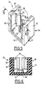
- FIG. 1 shows a front door of motor vehicle, designated by the general reference 10.
- the front edge of door 10 is on the left considering the figure 1.
- a window 12 is slidably mounted in the door 10.
- the door 10 has a lower part 14, forming box, and an upper part 16 forming a frame, delimiting a bay 18 which can be closed off by the window 12.
- the window 12 is movable between a low position retraction inside the box 14, as is shown in solid lines in Figure 1, and a position high shutter of bay 18.
- a low position retraction inside the box 14 as is shown in solid lines in Figure 1
- a position high shutter of bay 18 We have represented on the Figure 1 the window 12 partially in phantom in a intermediate position between its low and high positions.
- the door 10 comprises conventional means of displacement of the window 12 between its high and low positions, which is shown a substantially vertical rail 20.
- This rail allows the guidance of a carriage (not shown) for training of the glass, connected to this glass.
- the rail 20 is fixed in a manner known per se in the box 14.
- the glass 12 has two front edges 12A and rear 12B substantially parallel to the sliding direction of that window.
- the front edge 12A of the glass is mounted sliding in a slide 22, substantially rectilinear and vertical, fixed in a manner known per se to the front of the box 14 from the door.
- the rear edge 12B of the window is intended to cooperate with guide means 24 fixed to the rear of the box 14 Door.
- the window 12 is movable between its high and low positions through an upper slot, substantially longitudinal, of the box, provided with seals wipers 25 participating in guiding the window.
- a bar 26 substantially longitudinal, transverse protection of the passenger compartment of the vehicle.
- the guide means 24 are arranged substantially at the same height as this bar 26, of preferably in contact with this bar, as illustrated in Figures 1 and 2.
- the glass 12 on the one hand cooperates with the means of guide 24, when it is in the low position, as is illustrated in solid lines in FIG. 1, and on the other hand, is moved upwards from these guide means 24, when in the high position, as illustrated in dashed lines in Figure 1.
- the guide means 24 are illustrated on the Figures 1 to 4 according to a first embodiment of the invention. These guide means will be described in detail below referring essentially to Figures 2 to 4.
- the guide means 24 comprise a body 27 secured to door 10, carrying two deformable members 28 elastically, for example natural rubber or synthetic. These elastically deformable members are intended to pinch the opposite faces of the rear edge 12B of the window, when this window is in the low position.
- the body 27 has a general U shape and has a core 30 for fixing on the door and two wings 32, extending on either side of the opposite faces of the rear edge 12B of the window, each carrying a pinching member 28.
- the pinching members 28 are identical to each other. One of the members 28 is shown in detail in FIG. 4.
- the clamping members 28 are snapped into orifices 34 formed in the wings 32 of the body 27.
- This body 27 is made, for example, of light alloy.
- pinching members 28 are profiles according to a generally arrow-shaped profile provided a point 36 delimited by two ramps 38 of inclinations opposed.
- the tip 36 of a pinching member is connected to a heel 40 by means of a shaft 42 extending to through the corresponding orifice 34.
- Toe 36 and heel 40 of a pinching member 28 delimit shoulders of immobilization of this member 28 in the orifice 34 corresponding.
- the clamping members 28 extend longitudinally substantially perpendicular to the direction of sliding of the window 12.
- the clamping members 28 are arranged on the side and on the other side of the window 12.
- the tips 36 of these members are directed towards each other and are intended to cooperate with the opposite faces of the rear edge 12B of the window.
- the longitudinal dimension of the organs profile pinching is reduced compared to the dimension longitudinal of the window measured between the two front edges 12A and rear 12B of the window.
- the tips 36 of the pinching members 28 are provided with longitudinal bores 44 facilitating the deformation of these points in contact with the glass 12.
- one of the branches 32 of the body 27 is in contact with the bar protection 26 via the heel 40 of the pinch carried by this branch 32.
- the core 30 of the body is provided with a threaded insert 46 in which is screwed a screw 48 for fixing the body to the door 10.
- the head of this screw 48 is supported on an edge of the box 14.
- the surface of the pinching members 28, in contact with the glass 12 is treated, for example by flocking, so as to reduce friction with this window.
- the window 12 is in the high position, at the distance from the guide means 24, as shown in dashed lines in Figure 1.
- the window 12 When the window 12 is lowered, it is guided, during the first part of its downhill race, by the rail 20 (via the carriage which slides in this rail and which is connected to the glass 12), by the slide 22 (guiding the front edge 12A of the window 12) and by the seals lickers 25 and then for a second part of its stroke down and to its low position, by the elements of guidance 20,22,25 mentioned previously as well as by the means guide 24.
- the guide means 24 form means bracing between the glass 12, in the low position, and the protection bar 26, which prevents slamming harmful of the glass against the bar.
- the points 36 of the pinching members 28 guide and immobilize the window 12 in the low position so as to avoid any unwanted contact of this glass with others elements housed in the box 14 of the door.
- the pinching members 28 have come in one piece with the body 27.
- the latter comprises a metal insert 50.
- the core 30 and the branches 32 of the body are overmolded with clamping members 28 on the insert 50.
- the core 30 of the body is fixed to the door 10 by screwing and comprises, at for this purpose, a nut 52 welded to the core of the insert 50.
- the invention has many advantages.
- the guide means 24 according to the invention are adaptable to doors of various shapes.
Description
La présente invention concerne une porte à vitre coulissante, notamment pour véhicule automobile.The present invention relates to a glass door sliding, in particular for a motor vehicle.
On connaít déjà dans l'état de la technique une porte, notamment pour véhicule automobile, du type comprenant une vitre montée coulissante dans la porte entre deux positions haute et basse, la vitre comprenant un bord sensiblement parallèle à la direction de coulissement de la vitre destiné à coopérer avec des moyens de guidage portés par la porte.We already know in the prior art a door, in particular for a motor vehicle, of the type comprising a sliding glass in the door between two positions high and low, the window comprising an edge substantially parallel to the sliding direction of the glass intended for cooperate with guide means carried by the door.
FR-A-2 705 391 décrit une porte pour véhicule automobile du type précité. La vitre de cette porte présente deux bords avant et arrière coopérant avec deux glissières fixes avant et arrière. La porte comporte également un organe de calage destiné à coopérer avec la vitre lorsque celle-ci est en position haute.FR-A-2 705 391 describes a door for a vehicle automobile of the aforementioned type. The glass of this door has two front and rear edges cooperating with two slides fixed front and rear. The door also has a member wedging intended to cooperate with the window when the latter is in the high position.
Les moyens de guidage de la vitre décrits dans ce document sont spécifiques à la forme de la porte. Ces moyens de guidage ne peuvent donc pas être adaptés à des formes variées de porte.The glass guide means described in this document are specific to the shape of the door. These means guides cannot therefore be adapted to shapes various door.
DE-A-43 11 262 décrit une porte pour véhicule automobile également du type précité. Dans ce document, les moyens de guidage comprennent, pour chaque bord avant ou arrière de la vitre, au moins deux éléments en U disposés l'un au-dessus de l'autre. Ces éléments, constituant en fait des glissières, coopèrent avec jeu avec la vitre. Ainsi, les éléments en U autorisent un débattement de la vitre entre leurs branches nécessaire pour tenir compte des tolérances de cotes.DE-A-43 11 262 describes a door for a vehicle automobile also of the aforementioned type. In this document, the guide means include, for each front edge or rear of the glass, at least two U-shaped elements arranged one above each other. These elements, in fact constituting slides, cooperate with play with the window. So the U-shaped elements allow movement of the glass between their branches necessary to account for the tolerances of ratings.
L'invention a pour but de proposer des moyens de guidage d'une vitre adaptables sur des portes de formes variées, permettant d'éviter, notamment, le claquement de la vitre contre d'autres éléments logés dans la porte, lorsque la vitre est en position basse.The object of the invention is to propose means of guiding of a glass adaptable on shaped doors varied, making it possible to avoid, in particular, the clicking of the glass against other elements housed in the door, when the glass is in the low position.
A cet effet, l'invention a pour objet une porte, notamment pour véhicule automobile, du type précité, caractérisée en ce que la vitre, d'une part, est déplaçable en étant écartée des moyens de guidage lorsqu'elle est en position haute, et d'autre part, en coopérant avec les moyens de guidage lorsqu'elle est en position basse, de manière que la course de descente de la vitre entre ses positions haute et basse présente deux parties au cours desquelles la vitre, successivement, ne coopère pas puis coopère avec les moyens de guidage, les moyens de guidage pinçant la vitre lorsqu'elle coopère avec eux.To this end, the invention relates to a door, in particular for a motor vehicle, of the aforementioned type, characterized in that the glass, on the one hand, is movable by being separated from the guide means when in the high position, and on the other hand, by cooperating with the guide means when it is in the low position, so that the downward travel of the window between its high and low positions has two parts during which the glass, successively, does not not cooperate and then cooperate with the guide means, the guide means pinching the window when it cooperates with them.
Suivant des caractéristiques de différents modes de réalisation de l'invention :
- les moyens de guidage comprennent un corps, solidaire de la porte, portant deux organes déformables élastiquement, par exemple en caoutchouc naturel ou synthétique, destinés à pincer les faces opposées du bord de la vitre lorsque cette vitre coopère avec les moyens de guidage ;
- le corps a une forme générale en U et comporte une âme de fixation sur la porte et deux ailes s'étendant de part et d'autre des faces opposées du bord de la vitre, chaque aile portant un organe de pincement correspondant ;
- les organes de pincement sont profilés et s'étendent longitudinalement sensiblement perpendiculairement à la direction de coulissement de la vitre, les organes de pincement étant disposés symétriquement de part et d'autre de la vitre lorsque celle-ci est en position basse, la dimension longitudinale des organes de pincement profilés étant réduite par rapport à la dimension longitudinale de la vitre ;
- le profil des organes de pincement a une forme générale de flèche, chaque organe de pincement étant muni d'une pointe délimitée par deux rampes d'inclinaisons opposées, deux rampes symétriques des deux organes de pincement formant des moyens de centrage de la vitre;
- l'âme du corps est fixée sur la porte par vissage et comporte, à cet effet, un organe taraudé solidaire de l'âme ;
- la surface des organes de pincement en contact avec la vitre est traitée, par exemple par flocage, de manière à réduire les frottements avec cette vitre;
- les organes de pincement sont encliquetés dans des orifices ménagés dans les ailes du corps ;
- le corps et les organes de pincement sont venus de matière, le corps comportant un insert métallique en forme générale de U ;
- la porte comporte une barre, sensiblement longitudinale, de protection transversale de l'habitacle du véhicule, les moyens de guidage étant disposés sensiblement à la même hauteur que cette barre, de préférence au contact de cette barre.
- the guide means comprise a body, integral with the door, carrying two elastically deformable members, for example natural or synthetic rubber, intended to pinch the opposite faces of the edge of the window when this window cooperates with the guide means;
- the body has a general U shape and has a fixing core on the door and two wings extending on either side of the opposite faces of the edge of the glass, each wing carrying a corresponding pinching member;
- the pinching members are profiled and extend longitudinally substantially perpendicular to the sliding direction of the glass, the pinching members being arranged symmetrically on either side of the glass when the latter is in the low position, the longitudinal dimension profiled pinching members being reduced relative to the longitudinal dimension of the window;
- the profile of the gripping members has a general shape of arrow, each gripping member being provided with a point delimited by two ramps of opposite inclinations, two symmetrical ramps of the two gripping members forming means for centering the window;
- the core of the body is fixed to the door by screwing and comprises, for this purpose, a threaded member integral with the core;
- the surface of the pinching members in contact with the glass is treated, for example by flocking, so as to reduce friction with this glass;
- the pinching members are snapped into holes formed in the wings of the body;
- the body and the clamping members have come in one piece, the body comprising a metal insert in a general U shape;
- the door comprises a bar, substantially longitudinal, of transverse protection of the passenger compartment of the vehicle, the guide means being disposed substantially at the same height as this bar, preferably in contact with this bar.
L'invention sera mieux comprise à la lecture de la description qui va suivre donnée uniquement à titre d'exemple et faite en se référant aux dessins annexés dans lesquels :
- la figure 1 est une vue en perspective d'une porte selon l'invention munie de moyens de guidage de la vitre selon un premier mode de réalisation de cette invention;
- la figure 2 est une vue en coupe, à échelle agrandie, suivant le plan 2-2 de la figure 1 ;
- la figure 3 est une vue en coupe suivant la ligne 3-3 de la figure 2 ;
- la figure 4 est une vue en perspective d'un organe de pincement des moyens de guidage selon le premier mode de réalisation de l'invention ;
- la figure 5 est une vue en perspective des moyens de guidage de la vitre selon un second mode de réalisation de l'invention ;
- la figure 6 est une vue en coupe suivant la ligne 6-6 de la figure 5.
- Figure 1 is a perspective view of a door according to the invention provided with window guide means according to a first embodiment of this invention;
- Figure 2 is a sectional view, on an enlarged scale, along the plane 2-2 of Figure 1;
- Figure 3 is a sectional view along line 3-3 of Figure 2;
- Figure 4 is a perspective view of a clamping member of the guide means according to the first embodiment of the invention;
- Figure 5 is a perspective view of the window guide means according to a second embodiment of the invention;
- Figure 6 is a sectional view along line 6-6 of Figure 5.
On a représenté sur la figure 1 une porte avant de
véhicule automobile, désignée par la référence générale 10. Le
bord avant de la porte 10 est à gauche en considérant la
figure 1.FIG. 1 shows a front door of
motor vehicle, designated by the
Une vitre 12 est montée coulissante dans la porte 10.A
La porte 10 comporte une partie inférieure 14, formant
caisson, et une partie supérieure 16 formant cadre, délimitant
une baie 18 obturable par la vitre 12.The
La vitre 12 est déplaçable entre une position basse
d'escamotage à l'intérieur du caisson 14, comme cela est
représenté en traits pleins sur la figure 1, et une position
haute d'obturation de la baie 18. On a représenté sur la
figure 1 la vitre 12 partiellement en traits mixtes dans une
position intermédiaire entre ses positions basse et haute.The
La porte 10 comporte des moyens classiques de
déplacement de la vitre 12 entre ses positions haute et basse,
dont on a représenté un rail 20 sensiblement vertical. Ce rail
permet le guidage d'un chariot (non représenté) d'entraínement
de la vitre, relié à cette vitre.The
Le rail 20 est fixé de façon connue en soi dans le
caisson 14.The
La vitre 12 comporte deux bords avant 12A et arrière
12B sensiblement parallèles à la direction de coulissement de
cette vitre. Le bord avant 12A de la vitre est monté
coulissant dans une glissière 22, sensiblement rectiligne et
verticale, fixée de façon connue en soi à l'avant du caisson
14 de la porte.The
Le bord arrière 12B de la vitre est destiné à coopérer
avec des moyens de guidage 24 fixés à l'arrière du caisson 14
de la porte.The
De façon classique, la vitre 12 est déplaçable entre
ses positions haute et basse à travers une fente supérieure,
sensiblement longitudinale, du caisson, munie de joints
lécheurs 25 participant au guidage de la vitre.Conventionally, the
On a également représenté sur la figure 1 une barre
26, sensiblement longitudinale, de protection transversale de
l'habitacle du véhicule. Les moyens de guidage 24 sont
disposés sensiblement à la même hauteur que cette barre 26, de
préférence au contact de cette barre, comme cela est illustré
sur les figures 1 et 2.Also shown in Figure 1 a
La vitre 12, d'une part coopère avec les moyens de
guidage 24, lorsqu'elle est en position basse, comme cela est
illustré en traits pleins sur la figure 1, et d'autre part,
est écartée, vers le haut, de ces moyens de guidage 24,
lorsqu'elle est en position haute, comme cela est illustré en
traits mixtes sur la figure 1.The
Les moyens de guidage 24 sont illustrés sur les figures 1 à 4 selon un premier mode de réalisation de l'invention. Ces moyens de guidage seront décrits en détail ci-dessous en se référant essentiellement aux figures 2 à 4.The guide means 24 are illustrated on the Figures 1 to 4 according to a first embodiment of the invention. These guide means will be described in detail below referring essentially to Figures 2 to 4.
Les moyens de guidage 24 comprennent un corps 27
solidaire de la porte 10, portant deux organes 28 déformables
élastiquement, par exemple en caoutchouc naturel ou
synthétique. Ces organes déformables élastiquement sont
destinés à pincer les faces opposées du bord arrière 12B de la
vitre, lorsque cette vitre est en position basse.The guide means 24 comprise a
Le corps 27 a une forme générale en U et comporte une
âme 30 de fixation sur la porte et deux ailes 32, s'étendant
de part et d'autre des faces opposées du bord arrière 12B de
la vitre, portant chacun un organe de pincement 28.The
Les organes de pincement 28 sont identiques entre eux.
Un des organes 28 est représenté en détail sur la figure 4.The pinching
Les organes de pincement 28 sont encliquetés dans des
orifices 34 ménagés dans les ailes 32 du corps 27. Ce corps 27
est fabriqué par exemple en alliage léger.The clamping
On notera que les organes de pincement 28 sont
profilés selon un profil en forme générale de flèche muni
d'une pointe 36 délimitée par deux rampes 38 d'inclinaisons
opposées.It will be noted that the pinching
La pointe 36 d'un organe de pincement est reliée à un
talon 40 par l'intermédiaire d'une hampe 42 s'étendant à
travers l'orifice 34 correspondant. La pointe 36 et le talon
40 d'un organe de pincement 28 délimitent des épaulements
d'immobilisation de cet organe 28 dans l'orifice 34
correspondant.The
Les organes de pincement 28 s'étendent longitudinalement
sensiblement perpendiculairement à la direction de
coulissement de la vitre 12.The clamping
Les organes de pincement 28 sont disposés de part et
d'autre de la vitre 12. Les pointes 36 de ces organes sont
dirigées l'une vers l'autre et sont destinées à coopérer avec
les faces opposées du bord arrière 12B de la vitre.The clamping
On notera que la dimension longitudinale des organes de pincement profilés est réduite par rapport à la dimension longitudinale de la vitre mesurée entre les deux bords avant 12A et arrière 12B de la vitre.Note that the longitudinal dimension of the organs profile pinching is reduced compared to the dimension longitudinal of the window measured between the two front edges 12A and rear 12B of the window.
De préférence, les pointes 36 des organes de pincement
28 sont munies de perçages longitudinaux 44 facilitant la
déformation de ces pointes au contact de la vitre 12.Preferably, the
En se référant à la figure 3, on voit que les deux
rampes supérieures 38, symétriques, des deux organes de
pincement 28 forment des moyens de centrage de la vitre 12.Referring to Figure 3, we see that the two
En se référant à la figure 2, on notera qu'une des
branches 32 du corps 27 est en contact avec la barre de
protection 26 par l'intermédiaire du talon 40 de l'organe de
pincement porté par cette branche 32.Referring to Figure 2, note that one of the
En se référant toujours à la figure 2, on notera que
l'âme 30 du corps est munie d'un insert taraudé 46 dans lequel
est vissée une vis 48 de fixation du corps sur la porte 10. La
tête de cette vis 48 prend appui sur un bord du caisson 14.Referring always to FIG. 2, it will be noted that
the
De préférence, la surface des organes de pincement 28,
en contact avec la vitre 12, est traitée, par exemple par
flocage, de manière à réduire les frottements avec cette
vitre.Preferably, the surface of the pinching
On décrira ci-dessous le fonctionnement des moyens de
guidage 24 selon l'invention.We will describe below the functioning of the means of
Initialement, la vitre 12 est en position haute, à
l'écart des moyens de guidage 24, comme cela est représenté en
traits mixtes sur la figure 1.Initially, the
Lorsque la vitre 12 est baissée, celle-ci est guidée,
pendant une première partie de sa course de descente, par le
rail 20 (par l'intermédiaire du chariot qui coulisse dans ce
rail et qui est relié à la vitre 12), par la glissière 22
(guidant le bord avant 12A de la vitre 12) et par les joints
lécheurs 25, puis, pendant une seconde partie de sa course de
descente et jusqu'à sa position basse, par les éléments de
guidage 20,22,25 évoqués précédemment ainsi que par les moyens
de guidage 24.When the
Ainsi, la course de descente de la vitre 12 entre ses
positions haute et basse présente deux parties au cours
desquelles la vitre, successivement, ne coopère pas puis
coopère avec les moyens de guidage 24.Thus, the downward travel of the
Les moyens de guidage 24 forment des moyens
d'entretoisement entre la vitre 12, en position basse, et la
barre de protection 26, ce qui permet d'éviter le claquement
nuisible de la vitre contre la barre.The guide means 24 form means
bracing between the
Les pointes 36 des organes de pincement 28 guident et
immobilisent la vitre 12 en position basse de manière à éviter
tout contact indésirable de cette vitre contre d'autres
éléments logés dans le caisson 14 de la porte.The
Sur les figures 5 et 6, on a représenté des moyens de
guidage 24 selon un second mode de réalisation de l'invention.In Figures 5 and 6, there are shown means of
Sur ces figures, les éléments analogues à ceux des figures précédentes sont désignés par des références identiques.In these figures, elements similar to those of previous figures are designated by references identical.
Dans ce second mode de réalisation des moyens de
guidage, les organes de pincement 28 sont venus de matière
avec le corps 27. Ce dernier comporte un insert métallique 50.In this second embodiment of the means of
guide, the pinching
De préférence, l'âme 30 et les branches 32 du corps,
en caoutchouc synthétique ou naturel, sont surmoulées avec les
organes de pincement 28 sur l'insert 50.Preferably, the
Comme dans le mode de réalisation précédent, l'âme 30
du corps est fixée sur la porte 10 par vissage et comporte, à
cet effet, un écrou 52 soudé sur l'âme de l'insert 50.As in the previous embodiment, the
L'invention comporte de nombreux avantages.The invention has many advantages.
En particulier, les moyens de guidage 24 selon l'invention, de dimensions réduites, sont adaptables sur des portes de formes variées.In particular, the guide means 24 according to the invention, of reduced dimensions, are adaptable to doors of various shapes.
Par ailleurs, ils permettent d'éviter le claquement de la vitre contre des éléments logés dans le caisson de la porte, notamment contre la barre de protection de cette porte, ceci lorsque la vitre est en position basse.In addition, they prevent the snapping of the glass against elements housed in the box of the door, in particular against the protective bar of this door, this when the window is in the low position.
Claims (10)
- Door, particularly for a motor vehicle, of the type comprising a window (12) mounted to slide in the door between a raised position and a lowered position, the window (12) comprising an edge (12B) approximately parallel to the direction of sliding of the window intended to collaborate with guide means (24) carried by the door, characterized in that the window (12), on the one hand, is movable, by being moved away from the guide means (24) when in the raised position, and, on the other hand, by being in collaboration with the guide means (24) when it is in the lowered position, so that the downward travel of the window (12) between its raised and lowered positions is in two parts during which, in succession, the window does not collaborate with and then does collaborate with the guide means (24), the guide means (24) gripping the window (12) when it collaborates with them.
- Door according to Claim 1, characterized in that the guide means (24) comprise a body (27) secured to the door, carrying two elastically deformable members (28), for example made of natural or synthetic rubber, which are intended to grip the opposed sides of the edge (12B) of the window when this window is collaborating with the guide means (24).
- Door according to Claim 2, characterized in that the body (27) has the overall shape of a U and comprises a web (30) attaching to the door and two flanges (32) extending one on each side of the opposite sides of the edge (12B) of the window, each flange carrying a corresponding gripping member (28).
- Door according to Claim 2 or 3, characterized in that the gripping members (28) are profiled and run longitudinally approximately at right angles to the direction of sliding of the window (12), the gripping members (28) being arranged symmetrically on each side of the window (12) when the latter is in the lowered position, the longitudinal dimension of the profiled gripping members (28) being small by comparison with the longitudinal dimension of the window (12).
- Door according to Claim 4, characterized in that the profile of the gripping members (28) is in the general shape of an arrow, each gripping member (28) having a tip (36) delimited by two ramps (38) inclined in opposite directions, two symmetric ramps (38) of the two gripping members (28) forming means for centring the window (12),
- Door according to any one of Claims 3 to 5, characterized in that the web (30) of the body (27) is fixed to the door by screwing and for this purpose comprises a tapped member (46; 52) secured to the web (30).
- Door according to any one of Claims 2 to 6, characterized in that the surface of the gripping members (28) in contact with the window (12) is treated, for example by flock coating, so as to reduce the friction with this window.
- Door according to any one of Claims 2 to 7, characterized in that the gripping members (28) are clipped into orifices (34) formed in the flanges (32) of the body.
- Door according to any one of Claims 2 to 7, characterized in that the body (27) and the gripping members (28) are formed integrally with each other, the body (27) having a metal insert (50) in the overall shape of a U.
- Motor vehicle door according to any one of the preceding claims, characterized in that it comprises an approximately longitudinal protective bar (26), transverse with respect to the cabin of the vehicle, the guide means (24) being arranged at approximately the same height as this bar (26) and preferably in contact with this bar.
Applications Claiming Priority (2)
| Application Number | Priority Date | Filing Date | Title |
|---|---|---|---|
| FR9613984A FR2755909B1 (en) | 1996-11-15 | 1996-11-15 | SLIDING GLASS DOOR, ESPECIALLY FOR A MOTOR VEHICLE |
| FR9613984 | 1996-11-15 |
Publications (2)
| Publication Number | Publication Date |
|---|---|
| EP0842802A1 EP0842802A1 (en) | 1998-05-20 |
| EP0842802B1 true EP0842802B1 (en) | 2002-02-13 |
Family
ID=9497679
Family Applications (1)
| Application Number | Title | Priority Date | Filing Date |
|---|---|---|---|
| EP19970402736 Expired - Lifetime EP0842802B1 (en) | 1996-11-15 | 1997-11-14 | Door with sliding glass, especially for motor vehicle |
Country Status (3)
| Country | Link |
|---|---|
| EP (1) | EP0842802B1 (en) |
| DE (1) | DE69710420D1 (en) |
| FR (1) | FR2755909B1 (en) |
Families Citing this family (3)
| Publication number | Priority date | Publication date | Assignee | Title |
|---|---|---|---|---|
| FR2781726B1 (en) * | 1998-07-29 | 2000-11-10 | Peugeot | GLASS GUIDANCE SYSTEM FOR A MOTOR VEHICLE |
| FR2790783B1 (en) * | 1999-03-11 | 2001-06-29 | Allibert Ind | INTERIOR DOOR LINING WITH INTEGRATED WINDOW GUIDE AND DOOR THUS EQUIPPED |
| DE102019206842A1 (en) * | 2019-05-10 | 2020-05-07 | Audi Ag | Window pane arrangement for a vehicle door |
Family Cites Families (3)
| Publication number | Priority date | Publication date | Assignee | Title |
|---|---|---|---|---|
| FR2670162A1 (en) * | 1990-12-07 | 1992-06-12 | Hutchinson Sa | SEALING DEVICE FOR SLIDING OR FIXED WINDOW FRAME FRAME. |
| DE4311262C2 (en) * | 1993-04-06 | 1997-06-26 | Daimler Benz Ag | Window guide for motor vehicle doors |
| FR2705391B1 (en) | 1993-05-14 | 1995-06-23 | Renault | Device for guiding and retaining a descending window. |
-
1996
- 1996-11-15 FR FR9613984A patent/FR2755909B1/en not_active Expired - Fee Related
-
1997
- 1997-11-14 EP EP19970402736 patent/EP0842802B1/en not_active Expired - Lifetime
- 1997-11-14 DE DE69710420T patent/DE69710420D1/en not_active Expired - Lifetime
Also Published As
| Publication number | Publication date |
|---|---|
| EP0842802A1 (en) | 1998-05-20 |
| DE69710420D1 (en) | 2002-03-21 |
| FR2755909A1 (en) | 1998-05-22 |
| FR2755909B1 (en) | 1999-01-29 |
Similar Documents
| Publication | Publication Date | Title |
|---|---|---|
| EP0752338B1 (en) | Lockable slide for automotive vehicle seats | |
| FR2702711A1 (en) | Fixed glass for motor vehicles. | |
| FR2526733A1 (en) | SLIDE GUIDE FOR VEHICLE SEAT | |
| EP0568435A1 (en) | Sealing, especially intended to form a guide rail for a movable motor vehicle window pane | |
| EP3647093B1 (en) | Glazed vehicle device with removable guide shoe, door, vehicle and corresponding mounting method | |
| FR2774050A1 (en) | Motor vehicle windscreen wiper arm with cover for drive spindle head | |
| EP0307257B1 (en) | Guiding device for a sliding window | |
| EP0842802B1 (en) | Door with sliding glass, especially for motor vehicle | |
| EP0524053B1 (en) | Slide for vehicle seat with a device for play and noise reduction | |
| EP3356168A1 (en) | Flush-fitted glazed device for a vehicle door comprising a movable panel, and corresponding door and motor vehicle | |
| FR2525160A1 (en) | LEVER AND SLIDING ROOF WITH LEVER FOR LIFTING SUSPENDING TOGETHER ON GUIDE ARRANGEMENTS | |
| EP0565437B1 (en) | Air deflector for a windscreenwiper with a supple detachable edge | |
| EP0844355B1 (en) | Vehicle window regulator with compensation of parallelism failures in the guide rails | |
| FR2985223A1 (en) | Device for guiding window pane of door of car, has flexible lateral blade for guiding window pane, where window pane has shape that is complementary to shape of main groove, and rigid rod is encased on secondary groove | |
| FR2908445A1 (en) | Window regulator pair for motor vehicle, has lateral left and right windows, each window has slider slidingly guided on rail and including coupling sections which are respectively coupled with left and right windows | |
| EP0169747A1 (en) | Bumpers for a vehicle | |
| FR2562141A1 (en) | SLIDING GLASS FOR WINDOWS OF MOTOR VEHICLES, PARTICULARLY OF SPECIAL CARS. | |
| EP0220976A1 (en) | Sliding roof for a motor vehicle | |
| EP0439416B1 (en) | Slide for a vehicle seat | |
| EP1934081B1 (en) | Cover for a steering column | |
| FR2842767A1 (en) | Runner for vehicle seat comprises fixed section and movable transverse U-section with two vertical webs, seat fixing screw with widened head engages vertical web which has head retaining part | |
| FR2539680A1 (en) | Glazed motor vehicle door, equipped with a rack-type window winder | |
| EP0735225A1 (en) | Holding device for a windowpane slidingly mounted in a vehicle door | |
| FR2520307A1 (en) | SUPPORT BEARING FOR A TELESCOPIC TUBE SLIDING AXIALLY AND SWIVELING AROUND A TRANSVERSE AXIS | |
| FR2798341A1 (en) | Wiper for rear windscreen of a car comprises a wiper blade bent along a plane perpendicular to the windscreen's plan |
Legal Events
| Date | Code | Title | Description |
|---|---|---|---|
| PUAI | Public reference made under article 153(3) epc to a published international application that has entered the european phase |
Free format text: ORIGINAL CODE: 0009012 |
|
| AK | Designated contracting states |
Kind code of ref document: A1 Designated state(s): CH DE ES GB IT LI PT SE |
|
| AX | Request for extension of the european patent |
Free format text: AL;LT;LV;MK;RO;SI |
|
| 17P | Request for examination filed |
Effective date: 19981103 |
|
| AKX | Designation fees paid |
Free format text: CH DE ES GB IT LI PT SE |
|
| RBV | Designated contracting states (corrected) |
Designated state(s): CH DE ES GB IT LI PT SE |
|
| GRAG | Despatch of communication of intention to grant |
Free format text: ORIGINAL CODE: EPIDOS AGRA |
|
| 17Q | First examination report despatched |
Effective date: 20010308 |
|
| GRAG | Despatch of communication of intention to grant |
Free format text: ORIGINAL CODE: EPIDOS AGRA |
|
| GRAH | Despatch of communication of intention to grant a patent |
Free format text: ORIGINAL CODE: EPIDOS IGRA |
|
| GRAH | Despatch of communication of intention to grant a patent |
Free format text: ORIGINAL CODE: EPIDOS IGRA |
|
| GRAA | (expected) grant |
Free format text: ORIGINAL CODE: 0009210 |
|
| REG | Reference to a national code |
Ref country code: GB Ref legal event code: IF02 |
|
| AK | Designated contracting states |
Kind code of ref document: B1 Designated state(s): CH DE ES GB IT LI PT SE |
|
| PG25 | Lapsed in a contracting state [announced via postgrant information from national office to epo] |
Ref country code: IT Free format text: LAPSE BECAUSE OF FAILURE TO SUBMIT A TRANSLATION OF THE DESCRIPTION OR TO PAY THE FEE WITHIN THE PRESCRIBED TIME-LIMIT;WARNING: LAPSES OF ITALIAN PATENTS WITH EFFECTIVE DATE BEFORE 2007 MAY HAVE OCCURRED AT ANY TIME BEFORE 2007. THE CORRECT EFFECTIVE DATE MAY BE DIFFERENT FROM THE ONE RECORDED. Effective date: 20020213 Ref country code: GB Free format text: LAPSE BECAUSE OF FAILURE TO SUBMIT A TRANSLATION OF THE DESCRIPTION OR TO PAY THE FEE WITHIN THE PRESCRIBED TIME-LIMIT Effective date: 20020213 |
|
| REG | Reference to a national code |
Ref country code: CH Ref legal event code: EP |
|
| REF | Corresponds to: |
Ref document number: 69710420 Country of ref document: DE Date of ref document: 20020321 |
|
| PG25 | Lapsed in a contracting state [announced via postgrant information from national office to epo] |
Ref country code: SE Free format text: LAPSE BECAUSE OF FAILURE TO SUBMIT A TRANSLATION OF THE DESCRIPTION OR TO PAY THE FEE WITHIN THE PRESCRIBED TIME-LIMIT Effective date: 20020513 Ref country code: PT Free format text: LAPSE BECAUSE OF FAILURE TO SUBMIT A TRANSLATION OF THE DESCRIPTION OR TO PAY THE FEE WITHIN THE PRESCRIBED TIME-LIMIT Effective date: 20020513 |
|
| PG25 | Lapsed in a contracting state [announced via postgrant information from national office to epo] |
Ref country code: DE Free format text: LAPSE BECAUSE OF FAILURE TO SUBMIT A TRANSLATION OF THE DESCRIPTION OR TO PAY THE FEE WITHIN THE PRESCRIBED TIME-LIMIT Effective date: 20020514 |
|
| GBV | Gb: ep patent (uk) treated as always having been void in accordance with gb section 77(7)/1977 [no translation filed] |
Effective date: 20020213 |
|
| PG25 | Lapsed in a contracting state [announced via postgrant information from national office to epo] |
Ref country code: ES Free format text: LAPSE BECAUSE OF FAILURE TO SUBMIT A TRANSLATION OF THE DESCRIPTION OR TO PAY THE FEE WITHIN THE PRESCRIBED TIME-LIMIT Effective date: 20020829 |
|
| PG25 | Lapsed in a contracting state [announced via postgrant information from national office to epo] |
Ref country code: LI Free format text: LAPSE BECAUSE OF NON-PAYMENT OF DUE FEES Effective date: 20021130 Ref country code: CH Free format text: LAPSE BECAUSE OF NON-PAYMENT OF DUE FEES Effective date: 20021130 |
|
| PLBE | No opposition filed within time limit |
Free format text: ORIGINAL CODE: 0009261 |
|
| STAA | Information on the status of an ep patent application or granted ep patent |
Free format text: STATUS: NO OPPOSITION FILED WITHIN TIME LIMIT |
|
| 26N | No opposition filed |
Effective date: 20021114 |
|
| REG | Reference to a national code |
Ref country code: CH Ref legal event code: PL |