EP3647093B1 - Glazed vehicle device with removable guide shoe, door, vehicle and corresponding mounting method - Google Patents
Glazed vehicle device with removable guide shoe, door, vehicle and corresponding mounting method Download PDFInfo
- Publication number
- EP3647093B1 EP3647093B1 EP18203333.2A EP18203333A EP3647093B1 EP 3647093 B1 EP3647093 B1 EP 3647093B1 EP 18203333 A EP18203333 A EP 18203333A EP 3647093 B1 EP3647093 B1 EP 3647093B1
- Authority
- EP
- European Patent Office
- Prior art keywords
- runner
- guide
- glazed
- support
- panel
- Prior art date
- Legal status (The legal status is an assumption and is not a legal conclusion. Google has not performed a legal analysis and makes no representation as to the accuracy of the status listed.)
- Active
Links
- 238000000034 method Methods 0.000 title claims description 6
- 238000003780 insertion Methods 0.000 claims description 18
- 230000037431 insertion Effects 0.000 claims description 18
- 238000004026 adhesive bonding Methods 0.000 claims description 4
- 230000000903 blocking effect Effects 0.000 claims description 2
- 238000004519 manufacturing process Methods 0.000 claims description 2
- 230000014759 maintenance of location Effects 0.000 claims 4
- 230000002441 reversible effect Effects 0.000 claims 1
- 239000011521 glass Substances 0.000 description 9
- 238000002360 preparation method Methods 0.000 description 5
- 238000013459 approach Methods 0.000 description 3
- 239000011324 bead Substances 0.000 description 2
- 238000013461 design Methods 0.000 description 2
- 238000007789 sealing Methods 0.000 description 2
- 238000013519 translation Methods 0.000 description 2
- 230000000295 complement effect Effects 0.000 description 1
- 238000006073 displacement reaction Methods 0.000 description 1
- 238000012423 maintenance Methods 0.000 description 1
- 238000000926 separation method Methods 0.000 description 1
- 238000009966 trimming Methods 0.000 description 1
Images


Classifications
-
- B—PERFORMING OPERATIONS; TRANSPORTING
- B60—VEHICLES IN GENERAL
- B60J—WINDOWS, WINDSCREENS, NON-FIXED ROOFS, DOORS, OR SIMILAR DEVICES FOR VEHICLES; REMOVABLE EXTERNAL PROTECTIVE COVERINGS SPECIALLY ADAPTED FOR VEHICLES
- B60J1/00—Windows; Windscreens; Accessories therefor
- B60J1/08—Windows; Windscreens; Accessories therefor arranged at vehicle sides
- B60J1/12—Windows; Windscreens; Accessories therefor arranged at vehicle sides adjustable
- B60J1/16—Windows; Windscreens; Accessories therefor arranged at vehicle sides adjustable slidable
- B60J1/17—Windows; Windscreens; Accessories therefor arranged at vehicle sides adjustable slidable vertically
-
- B—PERFORMING OPERATIONS; TRANSPORTING
- B60—VEHICLES IN GENERAL
- B60J—WINDOWS, WINDSCREENS, NON-FIXED ROOFS, DOORS, OR SIMILAR DEVICES FOR VEHICLES; REMOVABLE EXTERNAL PROTECTIVE COVERINGS SPECIALLY ADAPTED FOR VEHICLES
- B60J1/00—Windows; Windscreens; Accessories therefor
- B60J1/004—Mounting of windows
-
- B—PERFORMING OPERATIONS; TRANSPORTING
- B60—VEHICLES IN GENERAL
- B60J—WINDOWS, WINDSCREENS, NON-FIXED ROOFS, DOORS, OR SIMILAR DEVICES FOR VEHICLES; REMOVABLE EXTERNAL PROTECTIVE COVERINGS SPECIALLY ADAPTED FOR VEHICLES
- B60J5/00—Doors
- B60J5/04—Doors arranged at the vehicle sides
- B60J5/0401—Upper door structure
- B60J5/0402—Upper door structure window frame details, including sash guides and glass runs
Definitions
- the field of the invention is that of motor vehicles.
- the invention relates to vehicle doors, and in particular to the equipment of openings formed in such doors.
- the invention relates to vehicle doors equipped with at least one substantially vertically movable glazed panel, in particular to pass from a closed position to an open position in which it penetrates entirely or partially into a lower body box (the movable panel can, of course, generally take a plurality of intermediate positions).
- Such a vehicle door can in particular be a side door, but the invention can also apply, for example, to hinged and/or sliding doors of a vehicle, including rear doors, tailgates, etc.
- the invention relates in particular to a glazed device, intended to be assembled with a bodywork box to form a vehicle door, on which the glazed surface is flush, that is to say according to which no frame appears seen from the outside.
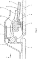
- a frame is provided, on the side oriented towards the interior of the vehicle, carrying one or more (typically two) rails, cooperating with runners secured to the movable glazed panel, and fixed to the face of the latter oriented towards inside the vehicle.
- the frame can, if necessary, be truncated and be limited to the uprights carrying the rails.
- a slider 2 of a movable glass panel 1 which slides in a guide rail 3, the slider being connected to the movable glass panel 1 and allowing the latter to be guided in displacement.
- This technique is interesting because it makes it possible to design original designs, due to the removal of the classic door frame, while maintaining a effective guiding and holding of the mobile panel.
- the assembly of the glazed device to the body box, to form the door can cause problems.
- a known solution consists of mounting the window equipped with pads in the guide devices (rails) and then assembling the assembly on the door structure. This solution requires integrating the assembly of a complete module on the assembly line. In addition, replacing the glass (for example, following an accident) requires complete dismantling of the module.
- Another known solution consists in mounting the window equipped with pads by the upper end of the guide rails.
- a disadvantage of this solution is that the door structure must be cut in the upper part to allow the passage of the window which can have consequences on the rigidity of the door. It is also necessary to add an upper crosspiece to the door after the glass has been fitted. This crosspiece must be removed when you wish to replace the glass.
- Yet another solution consists in mounting the window equipped with pads in the guide devices by deforming the guide zones of the pads.
- a final solution consists in separating the guide device into two parts, namely an inner part and an outer part.
- the interior part of the guide device is mounted on the door structure, then the window fitted with pads is mounted, and finally the outer part is mounted which closes the guide device and maintain the skate.
- a disadvantage of this solution is that it requires disassembling the outer part of the guide device when it is desired to replace the window.
- the object of the invention is in particular to overcome these disadvantages of the prior art.
- the object of the invention in at least one embodiment, is to provide a glazed device for producing a vehicle door, which is simple to implement and to assemble, for example, on a chain disassembly.
- Another object of the invention is to provide such a glazed device, which can be easily maintained or replaced, for example, following an accident.
- a glazed device intended to be assembled with a door box to form a motor vehicle door, comprising at least one movable glazed panel carrying, on its face facing the interior of the vehicle, at least one guide shoe mounted to slide with respect to a sliding guide rail of said movable glazed panel between a closed position and at least one open position.
- said at least one guide pad is reversibly mounted on a one-piece pad support fixedly mounted on said movable glazed panel, and said at least one guide pad and said at least one pad support are configured so that the guide shoe can be slidably inserted on the shoe holder by the upper and lower ends of the shoe holder.
- the invention thus proposes to implement a sliding guide shoe for a window relative to a vehicle door frame which has a structure in two parts.
- This particular structure of the guide pad(s) makes it possible to mount a window equipped with pad(s) in one or more guide rail(s), the pads guarantee maintenance of the window in the following guide rail(s).
- this particular structure of the guide shoe(s) ensures precise and predetermined guidance of the movable glazed panel in the guide rail(s).
- the guide pad or the corresponding pad support carries a device for holding the guide pad on the pad support.
- the holding device comprises a deformable snap-in tab carried by the pad support or the guide pad and adapted to cooperate with a recess provided on the guide pad or the pad support respectively.
- the glazed device comprises a device for holding the guide pad on the corresponding pad support taking the form of a pin passing through the guide pad and the pad support or of a part coming snap onto the guide shoe and the shoe holder.
- the pad support extends along one of the side edges of said movable glazed panel, on its face facing the interior of the vehicle.
- the pad support or the guide pad has a "T" shaped profile and the guide pad or the pad support respectively has a groove for receiving said profile of complementary shape said profile, so that the guide pad can be inserted by sliding on the pad support from one end of the pad support.
- the pad support is fixed directly to said movable glazed panel by gluing.
- the guide pad comprises at least one guide portion in the guide rail connected by an intermediate portion to a connection portion with the pad support and said movable glazed panel.
- said at least one movable glazed panel carries, on its face facing the interior of the vehicle, two guide pads positioned on the opposite side edges of the window and mounted to slide with respect to a corresponding guide rail.
- the invention also relates to a motor vehicle door fitted with a glazed device as described above, and motor vehicles fitted with at least one glazed device as described above.
- the guide shoe is temporarily held in position on the guide rail by means of a retaining device so as to facilitate the step of mounting the window on said at least one guide shoe.
- the approach of the invention differs from existing solutions in that it proposes to mount directly on the door a movable window not equipped with guide pads but only with support for skids, with simple mounting kinematics (mounting in the "Z" direction, for example).
- the approach of the invention also makes it possible to be able to simply separate the guide and support parts of the pads to facilitate the dismantling of the window in after-sales service.
- the invention therefore relates to a new technique for guiding the glazed part of a door (side door, rear door, tailgate, cabin door, etc.) of a motor vehicle whose glass, or mobile panel, is perfectly aligned and flush with the bodywork, that is to say that no frame or frame element protrudes outwards from the vehicle, relative to the plane of this glazed part.
- the invention relates to a novel structure for guiding the glazed panel intended to cooperate with a sliding guide rail of the glazed panel.
- This particular structure will be detailed later in relation to the figures 2 to 6B .
- the glazed device intended to be assembled with a door box to form a motor vehicle door, comprises a glazed panel, or pane, 1 movable bearing, on its face facing the interior of the vehicle, two one-piece (i.e. one-piece) 22 pad mounts.
- the shoe supports 22 are each connected to a guide shoe 21 mounted to slide with respect to a guide rail 3 in sliding mode of the glazed panel 1 which is movable between a closed position and at least one open position.
- the pad supports 22 connected to the guide pads 21 are each positioned on a panel side edge of the glazed panel 1, on its face facing the interior of the vehicle, the glazed panel 1 sliding along the vertical guide rails 3 of the door box, the guide rails 3 making it possible to guide the movable glass panel 1 in translation during its movement.
- the glazed panel 1 may only carry a single shoe support 22 connected to a single guide shoe 21 mounted to slide relative to a single guide rail 3.
- the movable glazed panel 1 is moved by drive means (not shown), for example a rack mechanism, itself actuated by an electric motor.
- drive means for example a rack mechanism, itself actuated by an electric motor.
- Other drive means including manual drive means, can of course be implemented.
- the movable glazed panel 1 is therefore slidably guided between two guide rails 3 located respectively at the front and at the rear of the door box by means of a pair (or more) of guide pads 21.
- the pad supports 22 and the corresponding guide pads 21 are fixed on the face of the movable glazed panel 1 oriented towards the interior of the vehicle, to cooperate with the guide rails 3. As illustrated in the schematic sectional view of the figure 2 , the guide pad 21 is mounted on a pad support 22 extending parallel to the movable glazed panel 1, along one of the side edges of the latter.
- the invention thus proposes to separate, on the pads, the functions of guiding and connecting with the window.
- the pad support 22 provides the connection with the window (for example by gluing) and the guide pad 21 is attached to this pad support 22.
- the guide shoe 21 can be attached to its shoe support 22 in the X, Y or Z directions.
- the Z direction is preferred because it is in this direction that the shoe/support assembly will undergo the lowest stresses.
- the guide pad 21 or the pad support 22 comprises a holding device 4 which locks the guide pad 21 on its support.
- This holding device 4 is designed in such a way as to resist window maneuvers in the direction Z and not to be stressed during exceptional forces (vandalism for example) in the directions X and Y. Furthermore, this holding device 4 can only be unlocked from the inside of the pane 1 to guarantee inviolability.
- the retaining device 4 is a deformable snap-in clip or tab carried by the pad support 22 (and located equidistant from the ends of the pad support 22) and adapted to cooperate with a recess 214 made on the outer surface of the connecting portion 213 of the guide pad 21 (equidistant from the ends of the guide pad 21).
- This latching tongue is housed in the recess 214 and blocks the guide shoe 21 on its support by pinching.
- the deformable tab can also be carried by the guide pad 21 and cooperate with a recess made on the pad support 22 (solution not shown).
- Two sealing lips 51, 52 are arranged on either side of the guide pad 21 and its support.
- the guide shoe 21 can be mounted at different stages of the assembly process of the glazed device.
- the guide rails 3 have a guide zone 32 of essentially circular section, the said corresponding guide pad(s) 21 comprising guide portions 211 which also have an essentially circular section.
- This cylindrical shape can in particular facilitate assembly and tolerate play.
- the Figure 3A shows on the one hand a movable glazed panel 1 carrying a pad support 22 and a guide pad 21 intended to be placed on the guide support 22 as illustrated in the Figure 3B .
- the arrows of the Figure 3B illustrate the way in which the guide pad 21 is inserted on its support (in a "Z" direction) by the upper or lower end of the guide support 22.
- guide pad 21 is secured to the guide support 22 of the glazed panel 1 movable once the latching tongue 4 cooperates with the recess 214 of the guide pad 21.
- the guide support 22 here has a "T" profile, the base of the guide support 22 being fixed to the inner surface of the glazed panel 1, the base carrying a bead coming to be housed in the interior space delimited by the portion of connection 213 of the guide pad 21.
- This interior space has a generally "U”-shaped section in which the bead of the guide support 22 can be housed and moved by sliding (this movement is no longer possible when the tongue of snap 4 cooperates with the recess 214 of the guide shoe 21).
- the figure 4 illustrates an example of unlocking the latching tab 4 forming a holding device from the inside of the window, using a tool O (this operation can however be carried out without a tool).
- the figures 5A to 5G illustrate the main steps of a first solution for assembling the glazed device on a vehicle side door.
- two sliding guide rails of the window are provided.
- the pad support(s) 22 are fixed to the window (for example by gluing).
- This retaining device can be constituted by a particular shape of the guide rail 3, by a breakable element of the guide rail 3 or of the guide shoe 21, or else by the addition of an insert.
- Said at least one guide shoe 21 is thus temporarily held in position on said at least one guide rail 3 by means of the retaining device so as to facilitate the step of mounting the window on said at least one guide shoe.
- the guide pads 21 are then temporarily blocked in sliding in a mounting position ( figure 5A ).
- the guide rails can carry decorative elements, such as a trim or a fixed window.
- the glazed panel 1 equipped with the shoe support(s) 22 is then mounted by inserting it partly into the lower door box P ( Fig. 5C ).
- seals can be mounted between these different steps.
- the position of the mounting of the seals in the assembly sequence can have an influence on the choice of the solution for mounting the guide pad(s) on the pad support(s).
- the window regulator can be fitted in the door before or after each of the various stages described above.
- the connection of the window with the window regulator can be done before or after the step illustrated on one of the figures 5D to 5G , the choice influencing the mode of assembly of the guide pad(s) on the pad support(s).
- trim elements can be fitted before one of the stages of the figure 5B and 5C , or before the step illustrated on one of the figures 5D to 5G . They can also be mounted in preparation on the guide rails.
- the figures 6A and 6B illustrate some of the steps of a second solution for assembling the glazed device on a vehicle side door.
- two guide rails 3 are provided sliding the glazed panel 1.
- the guide rail(s) 3 are mounted on the door structure P, by inserting them partly into the lower door box P ( Figure 6A ).
- the guide pad(s) 21 are mounted in the guide rail(s) 3 by inserting them into them by the end upper (a) or lower (b) of the guide rail(s) 3 ( figure 6B ).
- the guide pads 21 are held in the mounting position in the guide rails 3 by a wedging or blocking device as described above.
- the glazed panel 1 equipped with the shoe support(s) 22 is then mounted by inserting it partly into the lower door box P (as illustrated in Fig. 5C ).
Description
Le domaine de l'invention est celui des véhicules automobiles.The field of the invention is that of motor vehicles.
Plus précisément, l'invention concerne les portes de véhicule, et en particulier l'équipement de baies ménagées dans de telles portes.More specifically, the invention relates to vehicle doors, and in particular to the equipment of openings formed in such doors.
Plus précisément encore, l'invention concerne les portes de véhicule équipées d'au moins un panneau vitré mobile sensiblement verticalement, notamment pour passer d'une position fermée à une position ouverte dans laquelle il pénètre intégralement ou partiellement dans un caisson inférieur de carrosserie (le panneau mobile pouvant, bien sûr, prendre généralement, une pluralité de positions intermédiaires).More specifically still, the invention relates to vehicle doors equipped with at least one substantially vertically movable glazed panel, in particular to pass from a closed position to an open position in which it penetrates entirely or partially into a lower body box ( the movable panel can, of course, generally take a plurality of intermediate positions).
Une telle porte de véhicule peut notamment être une porte latérale, mais l'invention peut également s'appliquer, par exemple, aux portes battantes et/ou coulissantes d'un véhicule, y compris les portes arrière, les hayons...Such a vehicle door can in particular be a side door, but the invention can also apply, for example, to hinged and/or sliding doors of a vehicle, including rear doors, tailgates, etc.
L'invention concerne en particulier un dispositif vitré, destiné à être assemblé à un caisson de carrosserie pour former une porte de véhicule, sur lequel la surface vitrée est affleurant, c'est-à-dire selon lequel aucun cadre n'apparaît vu de l'extérieur.The invention relates in particular to a glazed device, intended to be assembled with a bodywork box to form a vehicle door, on which the glazed surface is flush, that is to say according to which no frame appears seen from the outside.
Des exemples de tels dispositifs sont décrits notamment dans les documents de brevet
Selon cette approche, un cadre est prévu, du côté orienté vers l'intérieur du véhicule, portant un ou plusieurs (classiquement deux) rails, coopérant avec des patins solidaires du panneau vitré mobile, et fixés sur la face de celui-ci orientée vers l'intérieur du véhicule. Le cadre peut, le cas échéant, être tronqué et être limité à des montants portant les rails. Sur la vue schématique en coupe de la
Cette technique est intéressante, car elle permet de concevoir des designs originaux, du fait de la suppression du cadre de porte classique, tout en conservant un guidage et un maintien efficaces du panneau mobile.This technique is interesting because it makes it possible to design original designs, due to the removal of the classic door frame, while maintaining a effective guiding and holding of the mobile panel.
Cependant, dans certains cas, l'assemblage du dispositif vitré au caisson de carrosserie, pour former la porte, peut causer problème.However, in some cases, the assembly of the glazed device to the body box, to form the door, can cause problems.
Une solution connue consiste à procéder au montage de la vitre équipée de patins dans les dispositifs de guidage (rails) puis à l'assemblage de l'ensemble sur la structure de porte. Cette solution nécessite d'intégrer sur ligne d'assemblage le montage d'un module complet. En outre, le remplacement de la vitre (par exemple, suite à un accident) nécessite un démontage complet du module.A known solution consists of mounting the window equipped with pads in the guide devices (rails) and then assembling the assembly on the door structure. This solution requires integrating the assembly of a complete module on the assembly line. In addition, replacing the glass (for example, following an accident) requires complete dismantling of the module.
Une autre solution connue consiste à procéder au montage de la vitre équipée de patins par l'extrémité supérieure des rails de guidage.Another known solution consists in mounting the window equipped with pads by the upper end of the guide rails.
Un inconvénient de cette solution est que la structure de porte doit être découpée en partie supérieure pour permettre le passage de la vitre ce qui peut avoir des conséquences sur la rigidité de la porte. Il est en outre nécessaire de rapporter une traverse supérieure sur la porte après montage de la vitre. Cette traverse doit être démontée lorsque l'on souhaite remplacer la vitre.A disadvantage of this solution is that the door structure must be cut in the upper part to allow the passage of the window which can have consequences on the rigidity of the door. It is also necessary to add an upper crosspiece to the door after the glass has been fitted. This crosspiece must be removed when you wish to replace the glass.
Encore une autre solution consiste à procéder au montage de la vitre équipée de patins dans les dispositifs de guidage par déformation des zones de guidage des patins.Yet another solution consists in mounting the window equipped with pads in the guide devices by deforming the guide zones of the pads.
Cette solution nécessite, après montage de la vitre, d'ajouter une pièce qui empêche le déclipsage du patin pour garantir la tenue en fonctionnement et l'inviolabilité.This solution requires, after assembly of the glass, to add a part which prevents the unclipping of the pad to guarantee the behavior in operation and the inviolability.
Une dernière solution consiste à séparer le dispositif de guidage en deux parties, à savoir une partie intérieure et une partie extérieure. Dans ce cas de figure, on procède au montage de la partie intérieure du dispositif de guidage sur la structure de porte, puis au montage de la vitre équipée de patins, et enfin au montage de la partie extérieure qui vient fermer le dispositif de guidage et maintenir le patin.A final solution consists in separating the guide device into two parts, namely an inner part and an outer part. In this case, the interior part of the guide device is mounted on the door structure, then the window fitted with pads is mounted, and finally the outer part is mounted which closes the guide device and maintain the skate.
Un inconvénient de cette solution est qu'elle nécessite de démonter la partie extérieure du dispositif de guidage lorsque l'on souhaite remplacer la vitre.A disadvantage of this solution is that it requires disassembling the outer part of the guide device when it is desired to replace the window.
L'invention a notamment pour objectif de pallier ces inconvénients de l'art antérieur.The object of the invention is in particular to overcome these disadvantages of the prior art.
Plus précisément, l'invention a pour objectif, dans au moins un mode de réalisation, de fournir un dispositif vitré pour la réalisation d'une porte de véhicule, qui soit simple à mettre en œuvre et à assembler, par exemple, sur une chaîne de montage.More specifically, the object of the invention, in at least one embodiment, is to provide a glazed device for producing a vehicle door, which is simple to implement and to assemble, for example, on a chain disassembly.
Un autre objectif de l'invention, selon au moins un mode de réalisation, est de fournir un tel dispositif vitré, qui puisse être aisément maintenu ou remplacé, par exemple, suite à un accident.Another object of the invention, according to at least one embodiment, is to provide such a glazed device, which can be easily maintained or replaced, for example, following an accident.
Ces objectifs, ainsi que d'autres qui apparaîtront par la suite sont atteints à l'aide d'un dispositif vitré destiné à être assemblé à un caisson de porte pour former une porte de véhicule automobile, comprenant au moins un panneau vitré mobile portant, sur sa face orientée vers l'intérieur du véhicule, au moins un patin de guidage monté coulissant par rapport à un rail de guidage en coulissement dudit panneau vitré mobile entre une position d'obturation et au moins une position d'ouverture.These objectives, as well as others which will appear subsequently, are achieved with the aid of a glazed device intended to be assembled with a door box to form a motor vehicle door, comprising at least one movable glazed panel carrying, on its face facing the interior of the vehicle, at least one guide shoe mounted to slide with respect to a sliding guide rail of said movable glazed panel between a closed position and at least one open position.
Selon l'invention, ledit au moins un patin de guidage est monté de façon réversible sur un support de patin monobloc monté fixe sur ledit panneau vitré mobile, et ledit au moins un patin de guidage et ledit au moins un support de patin sont configurés de sorte à ce que le patin de guidage puisse être inséré par coulissement sur le support de patin par les extrémités supérieure et inférieure du support de patin.According to the invention, said at least one guide pad is reversibly mounted on a one-piece pad support fixedly mounted on said movable glazed panel, and said at least one guide pad and said at least one pad support are configured so that the guide shoe can be slidably inserted on the shoe holder by the upper and lower ends of the shoe holder.
L'invention propose ainsi de mettre en œuvre un patin de guidage en coulissement d'une vitre relativement à un bâti de porte de véhicule qui présente une structure en deux parties.The invention thus proposes to implement a sliding guide shoe for a window relative to a vehicle door frame which has a structure in two parts.
Cette structure particulière du ou des patin(s) de guidage permet de monter une vitre équipée de patin(s) dans un ou des rail(s) de guidage, les patins garantit un maintien de la vitre dans le ou les rails de guidage suivant les directions X (correspondant à la longueur du véhicule) et/ou Y (correspondant à la largeur du véhicule).This particular structure of the guide pad(s) makes it possible to mount a window equipped with pad(s) in one or more guide rail(s), the pads guarantee maintenance of the window in the following guide rail(s). the directions X (corresponding to the length of the vehicle) and/or Y (corresponding to the width of the vehicle).
Elle permet en outre un montage pièce-à-pièce du dispositif vitré sur la ligne d'assemblage sur une porte de véhicule, et un remplacement facile de la vitre suite à un accident, par exemple.It also allows piece-by-piece assembly of the glazed device on the assembly line on a vehicle door, and easy replacement of the glass following an accident, for example.
Enfin, cette structure particulière du ou des patin(s) de guidage assure un guidage précis et prédéterminé du panneau vitré mobile dans le ou les rails de guidage.Finally, this particular structure of the guide shoe(s) ensures precise and predetermined guidance of the movable glazed panel in the guide rail(s).
Selon un aspect particulier de l'invention, le patin de guidage ou le support de patin correspondant porte un dispositif de maintien du patin de guidage sur le support de patin.According to a particular aspect of the invention, the guide pad or the corresponding pad support carries a device for holding the guide pad on the pad support.
Avantageusement, le dispositif de maintien comprend une languette d'encliquetage déformable portée par le support de patin ou le patin de guidage et adaptée pour coopérer avec un évidement ménagé sur le patin de guidage ou le support de patin respectivement.Advantageously, the holding device comprises a deformable snap-in tab carried by the pad support or the guide pad and adapted to cooperate with a recess provided on the guide pad or the pad support respectively.
Dans une variante de mise en œuvre, le dispositif vitré comprend un dispositif de maintien du patin de guidage sur le support de patin correspondant prenant la forme d'une goupille venant traverser le patin de guidage et le support de patin ou d'une pièce venant s'encliqueter sur le patin de guidage et le support de patin.In an implementation variant, the glazed device comprises a device for holding the guide pad on the corresponding pad support taking the form of a pin passing through the guide pad and the pad support or of a part coming snap onto the guide shoe and the shoe holder.
Préférentiellement, le support de patin s'étend le long d'un des bords latéral dudit panneau vitré mobile, sur sa face orientée vers l'intérieur du véhicule.Preferably, the pad support extends along one of the side edges of said movable glazed panel, on its face facing the interior of the vehicle.
Selon une mise en œuvre particulière de l'invention, le support de patin ou le patin de guidage présente un profil en forme de "T" et le patin de guidage ou le support de patin respectivement présente une rainure de réception dudit profil de forme complémentaire audit profil, de sorte à ce que le patin de guidage puisse être inséré par coulissement sur le support de patin à partir d'une extrémité du support de patin.According to a particular implementation of the invention, the pad support or the guide pad has a "T" shaped profile and the guide pad or the pad support respectively has a groove for receiving said profile of complementary shape said profile, so that the guide pad can be inserted by sliding on the pad support from one end of the pad support.
De façon avantageuse, le support de patin est fixé directement sur ledit panneau vitré mobile par collage.Advantageously, the pad support is fixed directly to said movable glazed panel by gluing.
Selon un aspect particulier de l'invention, le patin de guidage comprend au moins une portion de guidage dans le rail de guidage reliée par une portion intermédiaire à une portion de liaison avec le support de patin et ledit panneau vitré mobile.According to a particular aspect of the invention, the guide pad comprises at least one guide portion in the guide rail connected by an intermediate portion to a connection portion with the pad support and said movable glazed panel.
Selon une mise en œuvre particulière de l'invention, ledit au moins un panneau vitré mobile porte, sur sa face orientée vers l'intérieur du véhicule, deux patins de guidage positionnés sur les bords latéraux opposés de la vitre et montés coulissant par rapport à un rail de guidage correspondant.According to a particular implementation of the invention, said at least one movable glazed panel carries, on its face facing the interior of the vehicle, two guide pads positioned on the opposite side edges of the window and mounted to slide with respect to a corresponding guide rail.
L'invention concerne également une porte de véhicule automobile équipée d'un dispositif vitré tel que décrit ci-dessus, et les véhicules automobiles équipés d'au moins un dispositif vitré tel que décrit ci-dessus.The invention also relates to a motor vehicle door fitted with a glazed device as described above, and motor vehicles fitted with at least one glazed device as described above.
L'invention concerne également un procédé de fabrication et/ou de montage d'un dispositif vitré tel que décrit ci-dessus, comprenant les étapes de :
- fixation dudit au moins un support de patin sur ledit panneau vitré ;
- montage dudit au moins un rail de guidage sur la structure de porte ;
- positionnement dudit au moins un patin de guidage sur ledit au moins un rail de guidage avant ou après le montage dudit au moins un rail de guidage sur la structure de porte ;
- montage de la vitre portant ledit au moins un support de patin sur ledit au moins un patin de guidage par insertion et coulissement dudit au moins un patin de guidage sur ledit au moins un support de patin par les extrémités supérieure et inférieure du support de patin.
- fixing said at least one pad support on said glazed panel;
- mounting said at least one guide rail on the door structure;
- positioning said at least one guide shoe on said at least one guide rail before or after mounting said at least one guide rail on the door structure;
- mounting of the window carrying said at least one shoe support on said at least one guide shoe by inserting and sliding said at least one guide shoe on said at least one shoe support via the upper and lower ends of the shoe support.
De façon préférentielle, le patin de guidage est maintenu provisoirement en position sur le rail de guidage au moyen d'un dispositif de retenue de sorte à faciliter l'étape de montage de la vitre sur ledit au moins un patin de guidage.Preferably, the guide shoe is temporarily held in position on the guide rail by means of a retaining device so as to facilitate the step of mounting the window on said at least one guide shoe.
Dans le cadre d'un système flush pièce à pièce, l'approche de l'invention se différencie des solutions existantes en ce qu'elle propose de monter directement sur la porte une vitre mobile non équipée de patins de guidage mais uniquement de support de patins, avec une cinématique de montage simple (montage suivant la direction "Z", par exemple). L'approche de l'invention permet en outre de pouvoir séparer simplement les parties de guidage et de support des patins pour faciliter le démontage de la vitre en service après-vente.In the context of a piece-to-piece flush system, the approach of the invention differs from existing solutions in that it proposes to mount directly on the door a movable window not equipped with guide pads but only with support for skids, with simple mounting kinematics (mounting in the "Z" direction, for example). The approach of the invention also makes it possible to be able to simply separate the guide and support parts of the pads to facilitate the dismantling of the window in after-sales service.
L'invention, ainsi que les différents avantages qu'elle présente, seront plus facilement compris grâce à la description qui va suivre, donnée à titre simplement illustratif et non limitatif en référence aux figures annexées, parmi lesquelles :
- la
figure 1 est une vue en coupe schématique d'un dispositif vitré de porte de véhicule automobile de l'art antérieur ; - la
figure 2 est une vue en coupe schématique d'un dispositif vitré de porte de véhicule automobile conforme à l'invention ; - les
figures 3A et 3B est une vue partielle du dispositif vitré, vu du côté intérieur du véhicule, montrant le montage du patin de guidage en coulissement du panneau vitré mobile sur un support de patin fixé à ce dernier ; - la
figure 4 est une vue en coupe schématique d'un dispositif vitré de porte de véhicule automobile conforme à l'invention illustrant la séparation à l'aide d'un outil du patin de guidage et du support de patin ; - les
figures 5A à 5G illustrent les principales étapes d'une première solution d'assemblage du dispositif vitré conforme à l'invention sur une porte latérale de véhicule ; - les
figures 6A et6B illustrent certaines des étapes d'une deuxième solution d'assemblage du dispositif vitré conforme à l'invention sur une porte latérale de véhicule.
- the
figure 1 is a schematic cross-sectional view of a prior art motor vehicle door glazed device; - the
figure 2 is a schematic cross-sectional view of a glazed motor vehicle door device according to the invention; - the
figures 3A and 3B is a partial view of the glazed device, seen from the inside of the vehicle, showing the assembly of the sliding guide pad of the movable glazed panel on a pad support fixed to the latter; - the
figure 4 is a schematic cross-sectional view of a glazed motor vehicle door device according to the invention illustrating the separation using a tool of the guide pad and the pad support; - the
figures 5A to 5G illustrate the main steps of a first solution for assembling the glazed device according to the invention on a vehicle side door; - the
figures 6A and6B illustrate some of the steps of a second solution for assembling the glazed device according to the invention on a vehicle side door.
L'invention concerne donc une nouvelle technique de guidage de la partie vitrée d'une porte (porte latérale, porte arrière, hayon, porte de cabine...) de véhicule automobile dont la vitre, ou panneau mobile, est parfaitement alignée et affleurante avec la carrosserie, c'est-à-dire qu'aucun cadre ou élément de cadre ne fait saillie vers l'extérieur du véhicule, par rapport au plan de cette partie vitrée.The invention therefore relates to a new technique for guiding the glazed part of a door (side door, rear door, tailgate, cabin door, etc.) of a motor vehicle whose glass, or mobile panel, is perfectly aligned and flush with the bodywork, that is to say that no frame or frame element protrudes outwards from the vehicle, relative to the plane of this glazed part.
Plus précisément, l'invention concerne une nouvelle structure de patin de guidage du panneau vitré destiné à coopérer avec un rail de guidage en coulissement du panneau vitré. Cette structure particulière sera détaillée par la suite en relation avec les
Dans l'exemple illustré, le dispositif vitré destiné à être assemblé à un caisson de porte pour former une porte de véhicule automobile, comprend un panneau vitré, ou vitre, 1 mobile portant, sur sa face orientée vers l'intérieur du véhicule, deux supports de patin 22 monoblocs (c'est-à-dire en une seule pièce). Les supports de patin 22 sont reliés chacun à un patin de guidage 21 monté coulissant par rapport à un rail de guidage 3 en coulissement du panneau vitré 1 mobile entre une position d'obturation et au moins une position d'ouverture.In the example illustrated, the glazed device intended to be assembled with a door box to form a motor vehicle door, comprises a glazed panel, or pane, 1 movable bearing, on its face facing the interior of the vehicle, two one-piece (i.e. one-piece) 22 pad mounts. The shoe supports 22 are each connected to a
Les supports de patin 22 reliés aux patins de guidage 21 sont chacun positionnés sur un bord latéral panneau du panneau vitré 1, sur sa face orientée vers l'intérieur du véhicule, le panneau vitré 1 venant coulisser le long des rails de guidage 3 verticaux du caisson de porte, les rails de guidage 3 permettant de guider en translation le panneau vitré 1 mobile au cours de son déplacement.The pad supports 22 connected to the
Dans une variante, le panneau vitré 1 peut ne porter qu'un seul support de patin 22 relié à un unique patin de guidage 21 monté coulissant par rapport à un unique rail de guidage 3.Alternatively, the
Le panneau vitré 1 mobile est entraîné en déplacement par des moyens d'entraînement (non illustrés), par exemple un mécanisme à crémaillère, actionné lui-même par un moteur électrique. D'autres moyens d'entraînement, y compris des moyens d'entraînement manuels, peuvent bien sûr être mis en œuvre.The movable
Le panneau vitré 1 mobile est donc guidé en coulissement entre deux rails de guidage 3 situés respectivement à l'avant et à l'arrière du caisson de porte par l'intermédiaire d'une paire (ou plus) de patins de guidage 21.The movable
Les supports de patin 22 et les patins de guidage 21 correspondants sont fixés sur la face du panneau vitré 1 mobile orienté vers l'intérieur du véhicule, pour coopérer avec les rails de guidage 3. Comme illustré sur la vue schématique en coupe de la
L'invention propose ainsi de séparer, sur les patins, les fonctions de guidage et de liaison avec la vitre. Pour ce faire, le support de patin 22 assure la liaison avec la vitre (par exemple par collage) et le patin de guidage 21 est rapporté sur ce support de patin 22.The invention thus proposes to separate, on the pads, the functions of guiding and connecting with the window. To do this, the
Le patin de guidage 21 peut être rapporté sur son support de patin 22 suivant les directions X, Y ou Z. La direction Z est privilégiée car c'est suivant cette direction que l'assemblage patin/support subira les contraintes les plus faibles.The
Le patin de guidage 21 ou le support de patin 22 comprend un dispositif de maintien 4 qui bloque le patin de guidage 21 sur son support. Ce dispositif de maintien 4 est conçu de façon à résister aux manœuvres de vitre suivant la direction Z et à ne pas être sollicité lors d'efforts exceptionnels (vandalisme par exemple) suivant les directions X et Y. Par ailleurs, ce dispositif de maintien 4 ne peut être déverrouillé que depuis le côté intérieur de la vitre 1 pour garantir l'inviolabilité.The
Dans l'exemple ci-dessous, le dispositif de maintien 4 est un clip ou languette d'encliquetage déformable porté(e) par le support de patin 22 (et situé(e) à égale distance des extrémités du support de patin 22) et adapté(e) pour coopérer avec un évidement 214 ménagé sur la surface extérieure de la portion de liaison 213 du patin de guidage 21 (à égale distance des extrémités du patin de guidage 21).In the example below, the retaining
Cette languette d'encliquetage vient se loger dans l'évidement 214 et bloque le patin de guidage 21 sur son support par pincement.This latching tongue is housed in the
La languette déformable peut également être portée par le patin de guidage 21 et coopérer avec un évidement ménagé sur le support de patin 22 (solution non illustrée).The deformable tab can also be carried by the
D'autres dispositifs de maintien peuvent être utilisés (goupille, pièce rapportée à clipper,...).Other holding devices can be used (pin, clipped insert, etc.).
Deux lèvres d'étanchéité 51, 52 sont disposées de part et d'autre du patin de guidage 21 et de son support.Two sealing
Comme on le verra par la suite, le patin de guidage 21 peut être monté à différentes étapes du procédé d'assemblage du dispositif vitré.As will be seen later, the
Le rail de guidage 3 comprend notamment :
une zone 31 de solidarisation au châssis 7 du véhicule ;- une zone de guidage 32, apte à coopérer avec la ou les portions de guidage 211 d'un patin de guidage 21 de forme essentiellement sphérique (sur les
figures 3A et 3B , le patin de guidage 21 porte deux portions de guidage 211 situés à ses extrémités longitudinales). La section de cette zone de guidage 32 est essentiellement circulaire, avec une ouverture permettant le passage d'une portion intermédiaire 212 du patin 21 ; - une surface 33, sur laquelle
un enjoliveur 6 est rapporté et positionné de façon à être aligné avec le bord du panneau vitré 1 mobile tout en minimisant le jeu avec ce dernier, pour des raisons esthétiques.
- a
zone 31 for securing to thechassis 7 of the vehicle; - a
guide zone 32, capable of cooperating with the guide portion(s) 211 of aguide shoe 21 of essentially spherical shape (on thefigures 3A and 3B , theguide pad 21 carries twoguide portions 211 located at its longitudinal ends). The section of thisguide zone 32 is essentially circular, with an opening allowing the passage of anintermediate portion 212 of thepad 21; - a surface 33, on which a
trim 6 is attached and positioned so as to be aligned with the edge of the movableglazed panel 1 while minimizing play with the latter, for aesthetic reasons.
Ainsi, les rails de guidage 3 présentent une zone de guidage 32 de section essentiellement circulaire, le ou lesdits patins de guidage 21 correspondant comprenant des portions de guidage 211 qui présentent également une section essentiellement circulaire. Cette forme cylindrique peut notamment faciliter le montage et tolérer des jeux.Thus, the
D'autres sections des rails de guidage et des portions de guidage des patins, par exemple rectangulaires ou carrés, sont également possibles.Other sections of the guide rails and guide portions of the pads, for example rectangular or square, are also possible.
La
On comprend que le patin de guidage 21 est solidarisé au support de guidage 22 du panneau vitré 1 mobile une fois que la languette d'encliquetage 4 vient coopérer avec l'évidement 214 du patin de guidage 21.It is understood that the
Le support de guidage 22 présente ici un profil en "T", la base du support de guidage 22 étant fixé sur la surface intérieure du panneau vitré 1, la base portant un bourrelet venant se loger dans l'espace intérieur délimité par la portion de liaison 213 du patin de guidage 21. Cet espace intérieur présente une section globalement en "U" dans laquelle le bourrelet du support de guidage 22 peut venir se loger et se déplacer en coulissement (ce déplacement n'est plus possible lorsque la languette d'encliquetage 4 vient coopérer avec l'évidement 214 du patin de guidage 21).The
La
Les
Dans cet exemple, il est prévu deux rails de guidage en coulissement de la vitre.In this example, two sliding guide rails of the window are provided.
Selon une première étape (non illustrée), on procède à la fixation du ou des support(s) de patin(s) 22 sur la vitre (par exemple par collage).According to a first step (not shown), the pad support(s) 22 are fixed to the window (for example by gluing).
On procède, par ailleurs, au montage (
Ledit au moins un patin de guidage 21 est ainsi maintenu provisoirement en position sur ledit au moins un rail de guidage 3 au moyen du dispositif de retenue de sorte à faciliter l'étape de montage de la vitre sur ledit au moins un patin de guidage.Said at least one
Les patins de guidage 21 sont alors temporairement bloqués en coulissement dans une position de montage (
Dans le cas où deux rails de guidage sont mis en œuvre, ceux-ci peuvent être liés en préparation par au moins une traverse afin de garantir la distance entre ces deux rails de guidage. Sur les illustrations des
Les rails de guidage peuvent porter des éléments de décor, tels un enjoliveur ou une vitre fixe.The guide rails can carry decorative elements, such as a trim or a fixed window.
On procède ensuite au montage (
On monte ensuite le panneau vitré 1 équipé des support(s) de patin 22 en l'insérant en partie dans le caisson inférieur de porte P (
Enfin, on procède à la fixation du ou des support(s) de patin 22 du panneau vitré 1 sur le ou les patin(s) de guidage 21 (
En fonction de la position du ou des patin(s) de guidage 22 choisie lors de l'étape de préparation, plusieurs solutions sont envisageables :
- Solution A) de la
figure 5D - insertion du ou des patin(s) de guidage 21 sur le(s) support(s) de patin 22 en descendant le panneau vitré 1 (selon la flèche "a" sur lafigure 5D ) ou en montant le(s) patin(s) de guidage 21 (selon les flèches "b" sur lafigure 5D ) : le montage est effectué ici selon la direction « Z » ; - Solution B) de la
figure 5E - insertion du ou des patin(s) de guidage 21 sur le(s) support(s) de patin 22 en montant le panneau vitré 1 (selon la flèche "a" sur lafigure 5E ) ou en descendant le(s) patin(s) de guidage 21 (selon les flèches "b" sur lafigure 5E ) : le montage est effectué ici selon la direction « Z » ; - Solution C) de la
figure 5F - insertion du ou des patin(s) de guidage 21 sur le(s) support(s) de patin 22 suivant une direction perpendiculaire à la surface du panneau vitré 1: le montage est effectué ici selon la direction « Y », ou bien - Solution D) de la
figure 5G - insertion du ou des patin(s) sur le(s) support(s) de patin 22 en déplaçant le panneau vitré 1 suivant une direction perpendiculaire au(x) rails de guidage : le montage est effectué ici selon la direction « X » dans un des deux sens illustrés par les flèches.
- Solution A) of the
figure 5D - insertion of the guide pad(s) 21 on the pad support(s) 22 by descending the glazed panel 1 (according to the arrow "a" on thefigure 5D ) or by mounting the guide shoe(s) 21 (according to the arrows "b" on thefigure 5D ): mounting is performed here in the “Z” direction; - Solution B) of the
figure 5E - insertion of the guide pad(s) 21 on the pad support(s) 22 by mounting the glazed panel 1 (according to the arrow "a" on thefigure 5E ) or by lowering the guide shoe(s) 21 (according to the arrows "b" on thefigure 5E ): mounting is performed here in the “Z” direction; - Solution C) of the
figure 5F - insertion of the guide shoe(s) 21 on the shoe support(s) 22 in a direction perpendicular to the surface of the glazed panel 1: the assembly is carried out here in the "Y" direction, or else - Solution D) of the
figure 5G - insertion of the pad(s) on the pad support(s) 22 by moving theglazed panel 1 in a direction perpendicular to the guide rail(s): assembly is carried out here in the "X" direction in one of the two directions shown by the arrows.
On note que les joints d'étanchéité peuvent être montés entre ces différentes étapes. La position du montage des joints dans la séquence d'assemblage peut avoir une influence sur le choix de la solution de montage du ou des patin(s) de guidage sur le(s) support(s) de patin.Note that the seals can be mounted between these different steps. The position of the mounting of the seals in the assembly sequence can have an influence on the choice of the solution for mounting the guide pad(s) on the pad support(s).
On note par ailleurs que le montage du lève-vitre dans la porte peut intervenir avant ou après chacune des différentes étapes décrites précédemment. La liaison de la vitre avec le lève-vitre peut se faire avant ou après l'étape illustrée sur l'une des
Les éléments d'habillage (enjoliveur, vitre fixe,...) peuvent être montés avant une des étapes des
Les
Dans cet exemple, il est prévu deux rails de guidage 3 en coulissement du panneau vitré 1.In this example, two
Dans une première étape, on procède au montage du ou des rails de guidage 3 sur la structure de porte P, en les insérant en partie dans le caisson inférieur de porte P (
On note que dans le cas où deux rails de guidages 3 sont mis en œuvre, ceux-ci peuvent être liés en préparation par au moins une traverse. Sur les illustrations des
Dans une deuxième étape, on procède au montage du ou des patin(s) de guidage 21 dans le(s) rail(s) de guidage 3 en les insérant dans ceux-ci par l'extrémité supérieure (a) ou inférieure (b) du ou des rails de guidage 3 (
On monte ensuite le panneau vitré 1 équipé des support(s) de patin 22 en l'insérant en partie dans le caisson inférieur de porte P (comme illustré sur la
Enfin, on procède à la fixation du ou des support(s) de patin 22 du panneau vitré 1 sur le ou les patin(s) de guidage 21 (comme illustré sur les
En fonction de la position du ou des patin(s) de guidage 22 choisie lors de l'étape de préparation, plusieurs solutions sont envisageables :
- Solution A) de la
figure 5D - insertion du ou des patin(s) de guidage 21 sur le(s) support(s) de patin 22 en descendant le panneau vitré 1 (selon la flèche "a" sur lafigure 5D ) ou en montant le(s) patin(s) de guidage 21 (selon les flèches "b" sur lafigure 5D ) : le montage est effectué ici selon la direction « Z » ; - Solution B) de la
figure 5E - insertion du ou des patin(s) de guidage 21 sur le(s) support(s) de patin 22 en montant le panneau vitré 1 (selon la flèche "a" sur lafigure 5E ) ou en descendant le(s) patin(s) de guidage 21 (selon les flèches "b" sur lafigure 5E ) : le montage est effectué ici selon la direction « Z » ; - Solution C) de la
figure 5F - insertion du ou des patin(s) de guidage 21 sur le(s) support(s) de patin 22 suivant une direction perpendiculaire à la surface du panneau vitré 1: le montage est effectué ici selon la direction « Y », ou bien - Solution D) de la
figure 5G - insertion du ou des patin(s) sur le(s) support(s) de patin 22 en déplaçant le panneau vitré 1 suivant une direction perpendiculaire au(x) rails de guidage : le montage est effectué ici selon la direction « X » dans un des deux sens illustrés par les flèches.
- Solution A) of the
figure 5D - insertion of the guide pad(s) 21 on the pad support(s) 22 by descending the glazed panel 1 (according to the arrow "a" on thefigure 5D ) or by mounting the guide shoe(s) 21 (according to the arrows "b" on thefigure 5D ): mounting is performed here in the “Z” direction; - Solution B) of the
figure 5E - insertion of the guide pad(s) 21 on the pad support(s) 22 by mounting the glazed panel 1 (according to the arrow "a" on thefigure 5E ) or by lowering the guide shoe(s) 21 (according to the arrows "b" on thefigure 5E ): mounting is performed here in the “Z” direction; - Solution C) of the
figure 5F - insertion of the guide shoe(s) 21 on the shoe support(s) 22 in a direction perpendicular to the surface of the glazed panel 1: the assembly is carried out here in the "Y" direction, or else - Solution D) of the
figure 5G - insertion of the pad(s) on the pad support(s) 22 by moving theglazed panel 1 in a direction perpendicular to the guide rail(s): assembly is carried out here in the "X" direction in one of the two directions shown by the arrows.
Claims (13)
- Glazed device which is intended to be assembled on a door box in order to form a motor vehicle door (P), comprising at least one movable glazed panel (1) which carries, on the face thereof orientated towards the interior of the vehicle, at least one guide runner (21) which is mounted so as to slide relative to a guide rail (3) when the movable glazed panel (1) slides between a blocking position and at least one open position, the at least one guide runner (21) being mounted in a reversible manner on a monobloc runner support (22) which is mounted so as to be fixed to the movable glazed panel (1) and which has upper and lower ends, characterised in that the at least one guide runner (21) and the at least one runner support (22) are configured so that the guide runner (21) can be inserted by means of sliding on the runner support (22) via the upper and lower ends of the runner support (22).
- Glazed device according to claim 1, characterised in that the guiding runner (21) or the corresponding runner support (22) carries a retention device (4) of the guide runner (21) on the runner support (22).
- Glazed device according to claim 2, characterised in that the retention device (4) comprises a deformable snap-fit tab which is carried by the runner support (22) or the guide runner (21) and which is suitable for cooperating with a recess (214) provided on the guide runner (21) or the runner support (22), respectively.
- Glazed device according to claim 1, characterised in that it comprises a retention device (4) for the guide runner (21) on the corresponding runner support (22) in the form of a pin which extends through the guide runner (21) and the runner support (22) or a component which snap-fits on the guide runner (21) and the runner support (22).
- Glazed device according to any one of claims 1 to 4, characterised in that the runner support (22) extends along one of the lateral edges of the movable glazed panel (1) on the face thereof which is orientated towards the interior of the vehicle.
- Glazed device according to claim 5, characterised in that the runner support (22) or the guiding runner (21) has a T-shaped profile and the guide runner (21) or the runner support (22), respectively, has a groove which is for receiving the profile having a shape and which complements the profile so that the guide runner (21) can be inserted by means of sliding on the runner support (22) from an end of the runner support (22).
- Glazed support according to any one of claims 1 to 6, characterised in that the runner support (22) is fixed directly to the movable glazed panel (1) by means of adhesive bonding.
- Glazed device according to any one of claims 1 to 7, characterised in that the guide runner (21) comprises at least one guiding portion (211) in the guide rail (3) which is connected via an intermediate portion (212) to a connection portion (213) with the runner support (22) and the movable glazed panel (1).
- Glazed device according to any one of claims 1 to 8, characterised in that the at least one movable glazed panel (1) carries, on the face thereof which is orientated towards the interior of the vehicle, two guide runners (21) which are positioned on the opposing lateral edges of the glazed panel (1) and which are mounted so as to slide relative to a corresponding guide rail (3).
- Motor vehicle door (P), characterised in that it comprises a glazed device according to any one of claims 1 to 9.
- Motor vehicle, characterised in that it comprises at least one glazed device according to any one of claims 1 to 9.
- Method for producing and/or mounting a glazed device according to any one of claims 1 to 9 which comprises the steps of:- fixing the at least one runner support (22) to the glazed panel (1);- mounting the at least one guide rail (3) on the door structure;- positioning the at least one guide runner (21) on the at least one guide rail (3) before or after the assembly of the at least one guide rail (3) on the door structure;characterised in that it comprises the step of:- mounting the glazed panel (1) which carries the at least one runner support (22) on the at least one guide runner (21) by inserting and sliding the at least one guide runner (21) on the at least one runner support (22), the insertion of the at least one guide runner (21) being able to be carried out via the upper and lower ends of the runner support (22).
- Method according to claim 12, characterised in that the guide runner (21) is held provisionally in position on the guide rail (3) using a retention device in order to facilitate the step of mounting the glazed panel (1) on the at least one guide runner (21).
Priority Applications (1)
| Application Number | Priority Date | Filing Date | Title |
|---|---|---|---|
| EP18203333.2A EP3647093B1 (en) | 2018-10-30 | 2018-10-30 | Glazed vehicle device with removable guide shoe, door, vehicle and corresponding mounting method |
Applications Claiming Priority (1)
| Application Number | Priority Date | Filing Date | Title |
|---|---|---|---|
| EP18203333.2A EP3647093B1 (en) | 2018-10-30 | 2018-10-30 | Glazed vehicle device with removable guide shoe, door, vehicle and corresponding mounting method |
Publications (2)
| Publication Number | Publication Date |
|---|---|
| EP3647093A1 EP3647093A1 (en) | 2020-05-06 |
| EP3647093B1 true EP3647093B1 (en) | 2022-04-13 |
Family
ID=64048749
Family Applications (1)
| Application Number | Title | Priority Date | Filing Date |
|---|---|---|---|
| EP18203333.2A Active EP3647093B1 (en) | 2018-10-30 | 2018-10-30 | Glazed vehicle device with removable guide shoe, door, vehicle and corresponding mounting method |
Country Status (1)
| Country | Link |
|---|---|
| EP (1) | EP3647093B1 (en) |
Families Citing this family (4)
| Publication number | Priority date | Publication date | Assignee | Title |
|---|---|---|---|---|
| FR3076770B1 (en) * | 2018-01-18 | 2020-01-24 | Cooper Standard France | GUIDE DEVICE FOR A SLIDING GLASS, VEHICLE GLASS DOOR EQUIPPED WITH SUCH DEVICE AND VEHICLE EQUIPPED WITH SUCH A DOOR |
| DE102021101783A1 (en) | 2021-01-27 | 2022-07-28 | Bayerische Motoren Werke Aktiengesellschaft | GUIDE ELEMENT FOR MOTOR VEHICLE SIDE WINDOW |
| WO2023078531A1 (en) | 2021-11-02 | 2023-05-11 | Advanced Comfort Systems France Sas - Acs France | Glazed device for a vehicle door, comprising a flush-fitted movable panel, and corresponding door |
| WO2023078533A1 (en) | 2021-11-02 | 2023-05-11 | Advanced Comfort Systems France Sas - Acs France | Glazed device for a vehicle door, comprising a flush-fitted movable panel, and corresponding door |
Citations (2)
| Publication number | Priority date | Publication date | Assignee | Title |
|---|---|---|---|---|
| DE102016201106A1 (en) * | 2016-01-26 | 2017-07-27 | Brose Fahrzeugteile Gmbh & Co. Kommanditgesellschaft, Bamberg | Window regulator assembly with multi-part window guide element for a flush-mounted window concept and assembly method |
| EP3708756A1 (en) * | 2017-11-10 | 2020-09-16 | Shiroki Corporation | Door sash structure for vehicle door |
Family Cites Families (5)
| Publication number | Priority date | Publication date | Assignee | Title |
|---|---|---|---|---|
| IT1237689B (en) * | 1989-12-15 | 1993-06-15 | Fiat Auto Spa | DOOR FOR VEHICLES AND METHOD FOR THE REALIZATION OF THE SAME. |
| US7624537B2 (en) | 2002-11-21 | 2009-12-01 | Wagon Automotive Snc | Door of a motor vehicle with a sliding glass panel, and upper kit for door, corresponding method of manufacturing and vehicle |
| FR2872094B1 (en) | 2004-06-29 | 2006-09-15 | Wagon Sas | AUTOMOTIVE VEHICLE DOOR, STRUCTURE ASSEMBLY, GLASS ASSEMBLY, METHOD OF MANUFACTURE AND VEHICLE THEREFOR |
| JP5846159B2 (en) * | 2013-05-31 | 2016-01-20 | トヨタ自動車株式会社 | Window glass support structure |
| WO2018104592A1 (en) * | 2016-12-09 | 2018-06-14 | Advanced Comfort Systems France Sas - Acs France | Flush-fitted glazed device for a vehicle door comprising a movable panel, and corresponding door and motor vehicle |
-
2018
- 2018-10-30 EP EP18203333.2A patent/EP3647093B1/en active Active
Patent Citations (2)
| Publication number | Priority date | Publication date | Assignee | Title |
|---|---|---|---|---|
| DE102016201106A1 (en) * | 2016-01-26 | 2017-07-27 | Brose Fahrzeugteile Gmbh & Co. Kommanditgesellschaft, Bamberg | Window regulator assembly with multi-part window guide element for a flush-mounted window concept and assembly method |
| EP3708756A1 (en) * | 2017-11-10 | 2020-09-16 | Shiroki Corporation | Door sash structure for vehicle door |
Also Published As
| Publication number | Publication date |
|---|---|
| EP3647093A1 (en) | 2020-05-06 |
Similar Documents
| Publication | Publication Date | Title |
|---|---|---|
| EP3647093B1 (en) | Glazed vehicle device with removable guide shoe, door, vehicle and corresponding mounting method | |
| EP2512850B1 (en) | Motor vehicle trunk lid | |
| EP3356170A1 (en) | Flush glazed device for vehicle door, and corresponding door, motor vehicle, production method and sealing device | |
| EP0568435A1 (en) | Sealing, especially intended to form a guide rail for a movable motor vehicle window pane | |
| EP3582986B1 (en) | Flush glazed device for a vehicle door, door, motor vehicle, and corresponding production method and single-piece sealing device | |
| EP1612072B1 (en) | Motor vehicle door, structural assembly, glazed unit, method to manufacture and corresponding vehicles | |
| EP1022172B1 (en) | Process for manufacturing of a motor vehicle door, and corresponding door | |
| EP3356168B1 (en) | Flush-fitted glazed device for a vehicle door comprising a movable panel, and corresponding door and motor vehicle | |
| WO2020254201A1 (en) | Flush window module for a vehicle and method for mounting same | |
| FR2696376A1 (en) | Sealing strip which fits between fixed and moving glass panels in vehicles - is formed as peripheral strip, with additional vertical sealing and sliding strips | |
| EP0294254A1 (en) | Movable window, especially for a motor vehicle | |
| FR3021253A1 (en) | FLASHING WINDOW DEVICE FOR MOTOR VEHICLE DOOR WITH ADJUSTABLE MOBILE PANEL, DOOR AND MOTOR VEHICLE CORRESPONDING THERETO. | |
| FR2527256A2 (en) | DISCOVERABLE SURFACE OPENING DEVICE, IN PARTICULAR SUNROOF FOR MOTOR VEHICLE | |
| EP1422091B1 (en) | Vehicle door with slidable window pane, corresponding upper door module, vehicle and producing method | |
| EP1787839B1 (en) | Roller blind for motor vehicle with means to compensate for play and corresponding vehicle | |
| EP0985567B1 (en) | Roller blind with enclosure forming the upper part of a door; corresponding door and method to install | |
| EP3549803A1 (en) | Assembly by sliding of a window and a motor vehicle tailgate | |
| FR2985224A1 (en) | Glazed roof for car, has control unit that is utilized for alignment of surface directed towards outside of fixed portion, and another surface that is directed towards outside of panel when panel is in closed position | |
| EP0962346A1 (en) | Closing device for an aperture of a vehicle body, with exterior sliding and method for manufacturing and corresponding installation | |
| WO2023078533A1 (en) | Glazed device for a vehicle door, comprising a flush-fitted movable panel, and corresponding door | |
| EP1964698B1 (en) | Vehice door, vehicle door manufacturing method, vehicle with such a door, and corresponding vehicle door upper part | |
| WO2023147865A1 (en) | Device for closing off an opening made in the body of a vehicle, and corresponding vehicle | |
| EP3969306A1 (en) | Exterior sealing strip with adaptive trim | |
| WO2020126957A1 (en) | Glass panel with an encapsulated profiled joint comprising an attached piece secured by means of a hook | |
| EP1598513A1 (en) | Vehicle door with sliding window panel. |
Legal Events
| Date | Code | Title | Description |
|---|---|---|---|
| PUAI | Public reference made under article 153(3) epc to a published international application that has entered the european phase |
Free format text: ORIGINAL CODE: 0009012 |
|
| STAA | Information on the status of an ep patent application or granted ep patent |
Free format text: STATUS: THE APPLICATION HAS BEEN PUBLISHED |
|
| STAA | Information on the status of an ep patent application or granted ep patent |
Free format text: STATUS: REQUEST FOR EXAMINATION WAS MADE |
|
| AK | Designated contracting states |
Kind code of ref document: A1 Designated state(s): AL AT BE BG CH CY CZ DE DK EE ES FI FR GB GR HR HU IE IS IT LI LT LU LV MC MK MT NL NO PL PT RO RS SE SI SK SM TR |
|
| AX | Request for extension of the european patent |
Extension state: BA ME |
|
| 17P | Request for examination filed |
Effective date: 20200421 |
|
| RBV | Designated contracting states (corrected) |
Designated state(s): AL AT BE BG CH CY CZ DE DK EE ES FI FR GB GR HR HU IE IS IT LI LT LU LV MC MK MT NL NO PL PT RO RS SE SI SK SM TR |
|
| STAA | Information on the status of an ep patent application or granted ep patent |
Free format text: STATUS: EXAMINATION IS IN PROGRESS |
|
| STAA | Information on the status of an ep patent application or granted ep patent |
Free format text: STATUS: EXAMINATION IS IN PROGRESS |
|
| 17Q | First examination report despatched |
Effective date: 20201209 |
|
| GRAP | Despatch of communication of intention to grant a patent |
Free format text: ORIGINAL CODE: EPIDOSNIGR1 |
|
| STAA | Information on the status of an ep patent application or granted ep patent |
Free format text: STATUS: GRANT OF PATENT IS INTENDED |
|
| INTG | Intention to grant announced |
Effective date: 20211118 |
|
| GRAS | Grant fee paid |
Free format text: ORIGINAL CODE: EPIDOSNIGR3 |
|
| GRAA | (expected) grant |
Free format text: ORIGINAL CODE: 0009210 |
|
| STAA | Information on the status of an ep patent application or granted ep patent |
Free format text: STATUS: THE PATENT HAS BEEN GRANTED |
|
| AK | Designated contracting states |
Kind code of ref document: B1 Designated state(s): AL AT BE BG CH CY CZ DE DK EE ES FI FR GB GR HR HU IE IS IT LI LT LU LV MC MK MT NL NO PL PT RO RS SE SI SK SM TR |
|
| REG | Reference to a national code |
Ref country code: GB Ref legal event code: FG4D Free format text: NOT ENGLISH |
|
| REG | Reference to a national code |
Ref country code: CH Ref legal event code: EP |
|
| REG | Reference to a national code |
Ref country code: DE Ref legal event code: R096 Ref document number: 602018033699 Country of ref document: DE |
|
| REG | Reference to a national code |
Ref country code: IE Ref legal event code: FG4D Free format text: LANGUAGE OF EP DOCUMENT: FRENCH |
|
| REG | Reference to a national code |
Ref country code: AT Ref legal event code: REF Ref document number: 1483127 Country of ref document: AT Kind code of ref document: T Effective date: 20220515 |
|
| REG | Reference to a national code |
Ref country code: LT Ref legal event code: MG9D |
|
| REG | Reference to a national code |
Ref country code: NL Ref legal event code: MP Effective date: 20220413 |
|
| REG | Reference to a national code |
Ref country code: AT Ref legal event code: MK05 Ref document number: 1483127 Country of ref document: AT Kind code of ref document: T Effective date: 20220413 |
|
| PG25 | Lapsed in a contracting state [announced via postgrant information from national office to epo] |
Ref country code: NL Free format text: LAPSE BECAUSE OF FAILURE TO SUBMIT A TRANSLATION OF THE DESCRIPTION OR TO PAY THE FEE WITHIN THE PRESCRIBED TIME-LIMIT Effective date: 20220413 |
|
| PG25 | Lapsed in a contracting state [announced via postgrant information from national office to epo] |
Ref country code: SE Free format text: LAPSE BECAUSE OF FAILURE TO SUBMIT A TRANSLATION OF THE DESCRIPTION OR TO PAY THE FEE WITHIN THE PRESCRIBED TIME-LIMIT Effective date: 20220413 Ref country code: PT Free format text: LAPSE BECAUSE OF FAILURE TO SUBMIT A TRANSLATION OF THE DESCRIPTION OR TO PAY THE FEE WITHIN THE PRESCRIBED TIME-LIMIT Effective date: 20220816 Ref country code: NO Free format text: LAPSE BECAUSE OF FAILURE TO SUBMIT A TRANSLATION OF THE DESCRIPTION OR TO PAY THE FEE WITHIN THE PRESCRIBED TIME-LIMIT Effective date: 20220713 Ref country code: LT Free format text: LAPSE BECAUSE OF FAILURE TO SUBMIT A TRANSLATION OF THE DESCRIPTION OR TO PAY THE FEE WITHIN THE PRESCRIBED TIME-LIMIT Effective date: 20220413 Ref country code: HR Free format text: LAPSE BECAUSE OF FAILURE TO SUBMIT A TRANSLATION OF THE DESCRIPTION OR TO PAY THE FEE WITHIN THE PRESCRIBED TIME-LIMIT Effective date: 20220413 Ref country code: FI Free format text: LAPSE BECAUSE OF FAILURE TO SUBMIT A TRANSLATION OF THE DESCRIPTION OR TO PAY THE FEE WITHIN THE PRESCRIBED TIME-LIMIT Effective date: 20220413 Ref country code: ES Free format text: LAPSE BECAUSE OF FAILURE TO SUBMIT A TRANSLATION OF THE DESCRIPTION OR TO PAY THE FEE WITHIN THE PRESCRIBED TIME-LIMIT Effective date: 20220413 Ref country code: BG Free format text: LAPSE BECAUSE OF FAILURE TO SUBMIT A TRANSLATION OF THE DESCRIPTION OR TO PAY THE FEE WITHIN THE PRESCRIBED TIME-LIMIT Effective date: 20220713 Ref country code: AT Free format text: LAPSE BECAUSE OF FAILURE TO SUBMIT A TRANSLATION OF THE DESCRIPTION OR TO PAY THE FEE WITHIN THE PRESCRIBED TIME-LIMIT Effective date: 20220413 |
|
| PG25 | Lapsed in a contracting state [announced via postgrant information from national office to epo] |
Ref country code: RS Free format text: LAPSE BECAUSE OF FAILURE TO SUBMIT A TRANSLATION OF THE DESCRIPTION OR TO PAY THE FEE WITHIN THE PRESCRIBED TIME-LIMIT Effective date: 20220413 Ref country code: PL Free format text: LAPSE BECAUSE OF FAILURE TO SUBMIT A TRANSLATION OF THE DESCRIPTION OR TO PAY THE FEE WITHIN THE PRESCRIBED TIME-LIMIT Effective date: 20220413 Ref country code: LV Free format text: LAPSE BECAUSE OF FAILURE TO SUBMIT A TRANSLATION OF THE DESCRIPTION OR TO PAY THE FEE WITHIN THE PRESCRIBED TIME-LIMIT Effective date: 20220413 Ref country code: IS Free format text: LAPSE BECAUSE OF FAILURE TO SUBMIT A TRANSLATION OF THE DESCRIPTION OR TO PAY THE FEE WITHIN THE PRESCRIBED TIME-LIMIT Effective date: 20220813 |
|
| REG | Reference to a national code |
Ref country code: DE Ref legal event code: R097 Ref document number: 602018033699 Country of ref document: DE |
|
| PG25 | Lapsed in a contracting state [announced via postgrant information from national office to epo] |
Ref country code: SM Free format text: LAPSE BECAUSE OF FAILURE TO SUBMIT A TRANSLATION OF THE DESCRIPTION OR TO PAY THE FEE WITHIN THE PRESCRIBED TIME-LIMIT Effective date: 20220413 Ref country code: SK Free format text: LAPSE BECAUSE OF FAILURE TO SUBMIT A TRANSLATION OF THE DESCRIPTION OR TO PAY THE FEE WITHIN THE PRESCRIBED TIME-LIMIT Effective date: 20220413 Ref country code: RO Free format text: LAPSE BECAUSE OF FAILURE TO SUBMIT A TRANSLATION OF THE DESCRIPTION OR TO PAY THE FEE WITHIN THE PRESCRIBED TIME-LIMIT Effective date: 20220413 Ref country code: EE Free format text: LAPSE BECAUSE OF FAILURE TO SUBMIT A TRANSLATION OF THE DESCRIPTION OR TO PAY THE FEE WITHIN THE PRESCRIBED TIME-LIMIT Effective date: 20220413 Ref country code: DK Free format text: LAPSE BECAUSE OF FAILURE TO SUBMIT A TRANSLATION OF THE DESCRIPTION OR TO PAY THE FEE WITHIN THE PRESCRIBED TIME-LIMIT Effective date: 20220413 Ref country code: CZ Free format text: LAPSE BECAUSE OF FAILURE TO SUBMIT A TRANSLATION OF THE DESCRIPTION OR TO PAY THE FEE WITHIN THE PRESCRIBED TIME-LIMIT Effective date: 20220413 |
|
| PLBE | No opposition filed within time limit |
Free format text: ORIGINAL CODE: 0009261 |
|
| STAA | Information on the status of an ep patent application or granted ep patent |
Free format text: STATUS: NO OPPOSITION FILED WITHIN TIME LIMIT |
|
| 26N | No opposition filed |
Effective date: 20230116 |
|
| PG25 | Lapsed in a contracting state [announced via postgrant information from national office to epo] |
Ref country code: AL Free format text: LAPSE BECAUSE OF FAILURE TO SUBMIT A TRANSLATION OF THE DESCRIPTION OR TO PAY THE FEE WITHIN THE PRESCRIBED TIME-LIMIT Effective date: 20220413 |
|
| PG25 | Lapsed in a contracting state [announced via postgrant information from national office to epo] |
Ref country code: SI Free format text: LAPSE BECAUSE OF FAILURE TO SUBMIT A TRANSLATION OF THE DESCRIPTION OR TO PAY THE FEE WITHIN THE PRESCRIBED TIME-LIMIT Effective date: 20220413 Ref country code: MC Free format text: LAPSE BECAUSE OF FAILURE TO SUBMIT A TRANSLATION OF THE DESCRIPTION OR TO PAY THE FEE WITHIN THE PRESCRIBED TIME-LIMIT Effective date: 20220413 |
|
| REG | Reference to a national code |
Ref country code: CH Ref legal event code: PL |
|
| REG | Reference to a national code |
Ref country code: BE Ref legal event code: MM Effective date: 20221031 |
|
| GBPC | Gb: european patent ceased through non-payment of renewal fee |
Effective date: 20221030 |
|
| PG25 | Lapsed in a contracting state [announced via postgrant information from national office to epo] |
Ref country code: LU Free format text: LAPSE BECAUSE OF NON-PAYMENT OF DUE FEES Effective date: 20221030 |
|
| P01 | Opt-out of the competence of the unified patent court (upc) registered |
Effective date: 20230527 |
|
| PG25 | Lapsed in a contracting state [announced via postgrant information from national office to epo] |
Ref country code: LI Free format text: LAPSE BECAUSE OF NON-PAYMENT OF DUE FEES Effective date: 20221031 Ref country code: FR Free format text: LAPSE BECAUSE OF NON-PAYMENT OF DUE FEES Effective date: 20221031 Ref country code: CH Free format text: LAPSE BECAUSE OF NON-PAYMENT OF DUE FEES Effective date: 20221031 |
|
| PG25 | Lapsed in a contracting state [announced via postgrant information from national office to epo] |
Ref country code: BE Free format text: LAPSE BECAUSE OF NON-PAYMENT OF DUE FEES Effective date: 20221031 |
|
| PG25 | Lapsed in a contracting state [announced via postgrant information from national office to epo] |
Ref country code: IE Free format text: LAPSE BECAUSE OF NON-PAYMENT OF DUE FEES Effective date: 20221030 Ref country code: GB Free format text: LAPSE BECAUSE OF NON-PAYMENT OF DUE FEES Effective date: 20221030 |
|
| PG25 | Lapsed in a contracting state [announced via postgrant information from national office to epo] |
Ref country code: IT Free format text: LAPSE BECAUSE OF FAILURE TO SUBMIT A TRANSLATION OF THE DESCRIPTION OR TO PAY THE FEE WITHIN THE PRESCRIBED TIME-LIMIT Effective date: 20220413 |
|
| PGFP | Annual fee paid to national office [announced via postgrant information from national office to epo] |
Ref country code: DE Payment date: 20231026 Year of fee payment: 6 |
|
| PG25 | Lapsed in a contracting state [announced via postgrant information from national office to epo] |
Ref country code: HU Free format text: LAPSE BECAUSE OF FAILURE TO SUBMIT A TRANSLATION OF THE DESCRIPTION OR TO PAY THE FEE WITHIN THE PRESCRIBED TIME-LIMIT; INVALID AB INITIO Effective date: 20181030 |