EP0842709B1 - Process for continuously coating a metallurgical product in continuous motion with an organic coating and apparatus therefor - Google Patents
Process for continuously coating a metallurgical product in continuous motion with an organic coating and apparatus therefor Download PDFInfo
- Publication number
- EP0842709B1 EP0842709B1 EP97402397A EP97402397A EP0842709B1 EP 0842709 B1 EP0842709 B1 EP 0842709B1 EP 97402397 A EP97402397 A EP 97402397A EP 97402397 A EP97402397 A EP 97402397A EP 0842709 B1 EP0842709 B1 EP 0842709B1
- Authority
- EP
- European Patent Office
- Prior art keywords
- roller
- organic material
- tank
- coating
- bath
- Prior art date
- Legal status (The legal status is an assumption and is not a legal conclusion. Google has not performed a legal analysis and makes no representation as to the accuracy of the status listed.)
- Expired - Lifetime
Links
Images
Classifications
-
- B—PERFORMING OPERATIONS; TRANSPORTING
- B05—SPRAYING OR ATOMISING IN GENERAL; APPLYING FLUENT MATERIALS TO SURFACES, IN GENERAL
- B05C—APPARATUS FOR APPLYING FLUENT MATERIALS TO SURFACES, IN GENERAL
- B05C1/00—Apparatus in which liquid or other fluent material is applied to the surface of the work by contact with a member carrying the liquid or other fluent material, e.g. a porous member loaded with a liquid to be applied as a coating
- B05C1/04—Apparatus in which liquid or other fluent material is applied to the surface of the work by contact with a member carrying the liquid or other fluent material, e.g. a porous member loaded with a liquid to be applied as a coating for applying liquid or other fluent material to work of indefinite length
- B05C1/08—Apparatus in which liquid or other fluent material is applied to the surface of the work by contact with a member carrying the liquid or other fluent material, e.g. a porous member loaded with a liquid to be applied as a coating for applying liquid or other fluent material to work of indefinite length using a roller or other rotating member which contacts the work along a generating line
- B05C1/0813—Apparatus in which liquid or other fluent material is applied to the surface of the work by contact with a member carrying the liquid or other fluent material, e.g. a porous member loaded with a liquid to be applied as a coating for applying liquid or other fluent material to work of indefinite length using a roller or other rotating member which contacts the work along a generating line characterised by means for supplying liquid or other fluent material to the roller
-
- B—PERFORMING OPERATIONS; TRANSPORTING
- B05—SPRAYING OR ATOMISING IN GENERAL; APPLYING FLUENT MATERIALS TO SURFACES, IN GENERAL
- B05C—APPARATUS FOR APPLYING FLUENT MATERIALS TO SURFACES, IN GENERAL
- B05C1/00—Apparatus in which liquid or other fluent material is applied to the surface of the work by contact with a member carrying the liquid or other fluent material, e.g. a porous member loaded with a liquid to be applied as a coating
- B05C1/04—Apparatus in which liquid or other fluent material is applied to the surface of the work by contact with a member carrying the liquid or other fluent material, e.g. a porous member loaded with a liquid to be applied as a coating for applying liquid or other fluent material to work of indefinite length
- B05C1/08—Apparatus in which liquid or other fluent material is applied to the surface of the work by contact with a member carrying the liquid or other fluent material, e.g. a porous member loaded with a liquid to be applied as a coating for applying liquid or other fluent material to work of indefinite length using a roller or other rotating member which contacts the work along a generating line
- B05C1/0826—Apparatus in which liquid or other fluent material is applied to the surface of the work by contact with a member carrying the liquid or other fluent material, e.g. a porous member loaded with a liquid to be applied as a coating for applying liquid or other fluent material to work of indefinite length using a roller or other rotating member which contacts the work along a generating line the work being a web or sheets
- B05C1/0834—Apparatus in which liquid or other fluent material is applied to the surface of the work by contact with a member carrying the liquid or other fluent material, e.g. a porous member loaded with a liquid to be applied as a coating for applying liquid or other fluent material to work of indefinite length using a roller or other rotating member which contacts the work along a generating line the work being a web or sheets the coating roller co-operating with other rollers, e.g. dosing, transfer rollers
-
- B—PERFORMING OPERATIONS; TRANSPORTING
- B05—SPRAYING OR ATOMISING IN GENERAL; APPLYING FLUENT MATERIALS TO SURFACES, IN GENERAL
- B05D—PROCESSES FOR APPLYING FLUENT MATERIALS TO SURFACES, IN GENERAL
- B05D1/00—Processes for applying liquids or other fluent materials
- B05D1/18—Processes for applying liquids or other fluent materials performed by dipping
-
- B—PERFORMING OPERATIONS; TRANSPORTING
- B05—SPRAYING OR ATOMISING IN GENERAL; APPLYING FLUENT MATERIALS TO SURFACES, IN GENERAL
- B05D—PROCESSES FOR APPLYING FLUENT MATERIALS TO SURFACES, IN GENERAL
- B05D1/00—Processes for applying liquids or other fluent materials
- B05D1/28—Processes for applying liquids or other fluent materials performed by transfer from the surfaces of elements carrying the liquid or other fluent material, e.g. brushes, pads, rollers
Definitions
- the invention relates to the continuous application of a organic coating on a metallurgical product in scrolling, in particular the continuous coating of steel strips with resin.
- the steel strips after being rolled, can then undergo various metallurgical treatments, such as continuous annealing and electrogalvanizing, followed a finishing surface treatment per application an organic coating made of resin.
- the tank is continuously supplied with organic material liquid by means of a feed ramp plunging into the bath of said liquid organic material.
- This feed generates air bubbles on the surface of the bath which are entrained with the liquid organic material on the rollers in rotation, then finally transferred to the moving strip, thus altering its appearance of area.
- this partition used as an anti-bubble barrier only solves part of the problem posed by the transfer of the bubbles to the moving strip. Indeed the roller (s) whose lower part is submerged in the bath of liquid organic material generate by their rotation of air bubbles on the surface of the bath, which through the other rollers are going to be transferred to the running tape.
- rollers placed above the bath surface of liquid organic material generate also air bubbles on the surface of the bath when drop on the surface of the bath of excess material organic liquid not adhering to said rollers.
- the object of the invention is to propose a means preventing bubbles generated by rotating rollers and by the power rail to be transferred with the liquid organic material on the moving web and to alter its surface appearance.
- the subject of the invention is a method continuous application of an organic coating on a metallurgical product running from a bath liquid organic material in a container and likely to contain air bubbles, transfer of said liquid organic material on the product being produced in a coating area, characterized in that to eliminate said air bubbles, we create in at least a bath area, located upstream of said area coating, an updraft in the liquid material so as to bring the bubbles contained in the bath to the near its surface and cause it to burst.
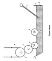
- the flow of the supply rail 1 is between 50 and 60 l / min adapted to the type of resin used. This feeding in liquid organic material 3 in tray 2 generates air bubbles on the surface of the bath.
- a roller called pick-up roller 4 the end of which lower is immersed in tray 2 containing the liquid organic material 3, transfers said material liquid organic on a roll called applicator roll 5, which in turn transfers the organic material liquid on the metallurgical product 7 in movement held by a holding roller 6.
- the speed of scrolling of the metallurgical product 7 is understood by example between 60 and 80 m / min.
- the rotation of the pick roller 4 generates the formation air bubbles when said roller attacks the surface of the bath. Some of these air bubbles can be driven with the rotation of said pick roller 4 and transferred with liquid organic material 3 to the applicator roller 5 then finally on the product metallurgical 7.
- a roller called a mobile roller 8 is interposed between the feed ramp 1 and the roller taker 4. It is immersed in its lower part in the bath of liquid organic material 3 at about 2 cm from the surface and rotated in the opposite direction to that of pick-up roller 4 to create in the liquid bath 3 in front of the coating area an updraft of so as to bring the air bubbles contained in the bath near the surface. Ideally the speed of rotation of the movable roller 8 is low, so that the rotational movement in the bath does not generate new air bubbles.
- the movable roller 8 has another advantage which is that of entraining the air bubbles adhering to its surface, which is no longer in contact with the material organic liquid 3 eventually burst.
- the bath of liquid organic material in the vicinity of the pick-up roller 4 is free of air bubbles and allows thus obtaining a strip coated with organic material having a very good surface appearance.
- An exemplary embodiment of the present invention uses a tank 2 shown diagrammatically in section, having vertical walls, namely an upstream wall x straight and an inclined downstream wall.
- the length of the tank 2 is 2.30 m, its width 95 cm at the top and 75 cm at the bottom and, its depth of 13 cm.
- the downstream wall is inclined there, in order to limit the disturbances in the liquid organic material bath 3.
- the feed ramp 1 placed near the vertical wall x of tank 2 consists of a pipe horizontal with a length of 1.55 m and a diameter of 3 4 cm to which four oblique pipes are connected, or vertical verticals of 16 cm and 3 to 4 cm in diameter, spaced 40 cm apart, the ends of which 3 to 4 mm in diameter immerse in the material bath liquid organic 3.
- the movable roller 8 consisting of a steel core coated with a 3 to 4 cm layer of rubber thick, 25 cm in diameter and 2 m long is immersed in the bath of liquid organic material 3 in its lower part to a depth of 2 cm.
- the spacing between the pick roller 4, consisting of steel core coated with chromium, 25 cm in diameter and length of about 2 m, and the movable roller 8 is 5 cm.
- the applicator roller 5 consisting of a core made of steel coated with a rubber layer with a diameter of 30 cm and about 2 m long, can be used up to a certain level of wear on the rubber, i.e. when the diameter of said roller reaches 25.5 cm.
- the running speed of the metallurgical product 7 is 60 to 80 m / min. If we take 100 as the basis for this speed, the speed of the applicator roller 5 varies from 130 to 160% of the scrolling speed, the speed of the take-up roller 4 varies from 40 to 60% of the speed of scrolling and the speed of the movable roller 8 is 5 to 15% (typically 10%) of the frame rate.
- Liquid organic materials 3 applied to metal strips 7 thanks to such an installation are for example very fluid resins whose viscosity dynamic is around 10 cP.
- resin used there may be mentioned SOLPLEX, resin based on silica commonly used in the automotive industry and whose coating thickness is around 7 ⁇ m in wet layer.
- the flow rate of the fuel rail pump varies between 50 to 60 l / min depending on the viscosity of the resin.
- roller mobile 8 can be replaced by any other means a moving surface whose movement creates a current ascending within the organic material bath.
Landscapes
- Coating Apparatus (AREA)
- Application Of Or Painting With Fluid Materials (AREA)
Abstract
Description
L'invention concerne l'application en continu d'un revêtement organique sur un produit métallurgique en défilement, en particulier l'enduction en continu des bandes d'acier par une résine.The invention relates to the continuous application of a organic coating on a metallurgical product in scrolling, in particular the continuous coating of steel strips with resin.
Les bandes d'acier, après avoir été laminées, peuvent subir ensuite divers traitements métallurgiques, tels qu'un recuit continu et un électrozingage, suivis d'un traitement de surface de finition par application d'un revêtement organique constitué de résine.The steel strips, after being rolled, can then undergo various metallurgical treatments, such as continuous annealing and electrogalvanizing, followed a finishing surface treatment per application an organic coating made of resin.
L'application en continu d'un matériau organique liquide tel qu'une résine ou une peinture s'effectue le plus souvent par enduction au rouleau. L'installation requise comporte un bac alimenté en continu par ledit matériau organique liquide au moyen d'une rampe d'alimentation. Une série de rouleaux en rotation, dont la partie inférieure de l'un d'entre eux au moins est immergée dans le bac, sont agencés de façon à ce que le matériau organique liquide soit appliqué uniformément sur la bande en défilement.Continuous application of organic material liquid such as resin or paint is done on more often by roller coating. The installation required includes a tank continuously fed by said liquid organic material by means of a ramp Power. A series of rotating rollers, the lower part of at least one of them is immersed in the tank, are arranged so that the liquid organic material is applied evenly over the running tape.
Le bac est alimenté continûment en matériau organique liquide au moyen d'une rampe d'alimentation plongeant dans le bain dudit matériau organique liquide. Cette alimentation génère des bulles d'air en surface du bain qui sont entraínées avec le matériau organique liquide sur les rouleaux en rotation, puis finalement transférées sur la bande en défilement, altérant ainsi son aspect de surface.The tank is continuously supplied with organic material liquid by means of a feed ramp plunging into the bath of said liquid organic material. This feed generates air bubbles on the surface of the bath which are entrained with the liquid organic material on the rollers in rotation, then finally transferred to the moving strip, thus altering its appearance of area.
Un moyen connu de pallier cet inconvénient est de placer dans le bac une cloison faisant office de barrage entre la rampe d'alimentation et les rouleaux en rotation. Les bulles d'air stagnant à la surface du bain sont ainsi retenues par la cloison, un passage ménagé dans la partie inférieure du bac permettant la libre circulation du matériau organique liquide débarrassé des bulles d'air, et par suite l'obtention de bandes ayant un bon aspect de surface.One known way to overcome this drawback is to place in the bin a partition acting as a barrier between the feed ramp and the rotating rollers. Air bubbles stagnating on the surface of the bath are thus retained by the partition, a passage in the part bottom of the tank allowing the free circulation of liquid organic material free of air bubbles, and consequently obtaining bands having a good aspect of area.
Cependant cette cloison utilisée comme barrage anti-bulles ne résout qu'une partie du problème posé par le transfert des bulles sur la bande en défilement. En effet le ou les rouleaux dont la partie inférieure est immergée dans le bain de matériau organique liquide génèrent de par leur rotation des bulles d'air à la surface du bain, qui par l'intermédiaire des autres rouleaux vont être transférées sur la bande en défilement.However, this partition used as an anti-bubble barrier only solves part of the problem posed by the transfer of the bubbles to the moving strip. Indeed the roller (s) whose lower part is submerged in the bath of liquid organic material generate by their rotation of air bubbles on the surface of the bath, which through the other rollers are going to be transferred to the running tape.
De surcroít, les rouleaux placés au dessus de la surface du bain de matériau organique liquide génèrent également des bulles d'air à la surface du bain lors de la chute sur la surface du bain de l'excès de matériau organique liquide n'adhérant pas auxdits rouleaux.In addition, the rollers placed above the bath surface of liquid organic material generate also air bubbles on the surface of the bath when drop on the surface of the bath of excess material organic liquid not adhering to said rollers.
Le but de l'invention est de proposer un moyen empêchant les bulles générées par les rouleaux en rotation et par la rampe d'alimentation d'être transférées avec le matériau organique liquide sur la bande en défilement et d'en altérer son aspect de surface.The object of the invention is to propose a means preventing bubbles generated by rotating rollers and by the power rail to be transferred with the liquid organic material on the moving web and to alter its surface appearance.
A cet effet, l'invention a pour objet un procédé d'application en continu d'un revêtement organique sur un produit métallurgique en défilement à partir d'un bain d'un matériau organique liquide contenu dans un bac et susceptible de contenir des bulles d'air, le transfert dudit matériau organique liquide sur le produit étant réalisé dans une zone d'enduction, caractérisé en ce que pour éliminer lesdites bulles d'air, on crée dans au moins une zone du bain, située en amont de ladite zone d'enduction, un courant ascendant dans le matériau liquide de manière à amener les bulles contenues dans le bain au voisinage de sa surface et provoquer leur éclatement.To this end, the subject of the invention is a method continuous application of an organic coating on a metallurgical product running from a bath liquid organic material in a container and likely to contain air bubbles, transfer of said liquid organic material on the product being produced in a coating area, characterized in that to eliminate said air bubbles, we create in at least a bath area, located upstream of said area coating, an updraft in the liquid material so as to bring the bubbles contained in the bath to the near its surface and cause it to burst.
L'invention a également pour objet un dispositif d'application en continu d'un revêtement organique sur un produit métallurgique 7 en défilement pour la mise en oeuvre du procédé précédemment décrit, ledit dispositif comprenant:
- un
bac 2 contenant un matériau organique liquide 3, - une rampe 1 plongeant dans le bain de matériau
organique 3 et alimentant continûment le
bac 2 en matériau organique liquide 3, - des moyens de défilement du produit métallurgique
comportant un rouleau dit rouleau de
maintien 6, - un rouleau dit rouleau preneur 4 dont la partie
inférieure est immergée dans ledit
bac 2 contenant le matériau organique liquide 3, ledit rouleau preneur 4 transférant le matériau organique 3 sur un rouleau ditrouleau applicateur 5 lequel transfère à son tour le matériau organique 3 sur le produit métallurgique 7 en défilement, caractérisé en ce qu'il comporte des moyens pour créer un courant ascendant dans au moins une zone du bac placée entre la rampe d'alimentation 1 et le rouleau preneur 4, pour retenir les bulles d'air générées par la rampe d'alimentation 1 et attirer les bulles d'air générées par le rouleau preneur 4 et par la chute dans le bac du matériau organique non adhérant au point de contact durouleau applicateur 5 et du rouleau preneur 4.
- a
tank 2 containing a liquid organic material 3, - a ramp 1 dipping into the bath of organic material 3 and continuously supplying the
tank 2 with liquid organic material 3, - means for running the metallurgical product comprising a roller known as a
holding roller 6, - a roller called pick-up roller 4, the lower part of which is immersed in said
tank 2 containing the liquid organic material 3, said pick-up roller 4 transferring the organic material 3 onto a roll calledapplication roller 5 which in turn transfers the organic material 3 onto themetallurgical product 7 in movement, characterized in that it comprises means for creating an ascending current in at least one area of the tank placed between the feed ramp 1 and the pick roller 4, to retain the air bubbles generated by the feed ramp 1 and attract the air bubbles generated by the pick-up roller 4 and by the fall into the tank of organic material not adhering to the point of contact of theapplicator roll 5 and the take-up roller 4.
L'invention sera mieux comprise à la lecture de la description qui suit, donnée en référence à la figure unique annexée qui représente schématiquement, vu en coupe longitudinale, un exemple d'un dispositif anti-bulles d'une installation de revêtement selon l'invention.The invention will be better understood on reading the description which follows, given with reference to the figure single annexed which represents schematically, seen in section longitudinal, an example of an anti-bubble device of a coating installation according to the invention.
Une rampe d'alimentation 1 plongeant dans un bac 2 de
matériau organique liquide 3, ledit matériau organique
étant une résine à l'état liquide, alimente ledit bac en
continu en ce matériau organique liquide. Le débit de la
rampe d'alimentation 1 est compris entre 50 et 60 l/mn
adapté au type de résine utilisée. Cette alimentation en
matériau organique liquide 3 dans le bac 2 génère des
bulles d'air à la surface du bain.A feed ramp 1 plunging into a
Un rouleau dit rouleau preneur 4, dont l'extrémité
inférieure est immergée dans le bac 2 contenant le
matériau organique liquide 3, transfère ledit matériau
organique liquide sur un rouleau dit rouleau applicateur
5, lequel transfère à son tour le matériau organique
liquide sur le produit métallurgique 7 en défilement
maintenu par un rouleau de maintien 6. La vitesse de
défilement du produit métallurgique 7 est comprise par
exemple entre 60 et 80 m/mn.A roller called pick-up roller 4, the end of which
lower is immersed in
La rotation du rouleau preneur 4 génère la formation
de bulles d'air lorsque ledit rouleau attaque la surface
du bain. Une partie de ces bulles d'air peuvent être
entraínées avec la rotation dudit rouleau preneur 4 et
transférées avec le matériau organique liquide 3 sur le
rouleau applicateur 5 puis finalement sur le produit
métallurgique 7.The rotation of the pick roller 4 generates the formation
air bubbles when said roller attacks the surface
of the bath. Some of these air bubbles can be
driven with the rotation of said pick roller 4 and
transferred with liquid organic material 3 to the
L'excès de matériau organique n'adhérant pas aux
points de contact du rouleau preneur 4 et du rouleau
applicateur 5 provoque la chute d'égouttures dudit
matériau organique liquide dans le bain, provoquant la
formation de bulles d'air à la surface du bain de matériau
organique liquide 3.Excess organic material not adhering to
pickup roller 4 and roller
Selon l'invention un rouleau dit rouleau mobile 8 est
interposé entre la rampe d'alimentation 1 et le rouleau
preneur 4. Il est immergé dans sa partie inférieure dans
le bain de matériau organique liquide 3 à environ 2 cm de
la surface et mis en rotation en sens inverse de celui du
rouleau preneur 4 afin de créer dans le bain de liquide 3
en avant de la zone d'enduction un courant ascendant de
manière à amener les bulles d'air contenues dans le bain
au voisinage de la surface. Idéalement la vitesse de
rotation du rouleau mobile 8 est faible, afin que le
mouvement de rotation dans le bain ne génère pas de
nouvelles bulles d'air.According to the invention, a roller called a
Le rouleau mobile 8 présente un autre avantage qui
est celui d'entraíner les bulles d'air adhérant à sa
surface, qui n'étant plus en contact avec le matériau
organique liquide 3 finissent par éclater.The
Le bain de matériau organique liquide au voisinage du rouleau preneur 4 est exempt de bulles d'air et permet ainsi d'obtenir une bande revêtue du matériau organique ayant un très bon aspect de surface.The bath of liquid organic material in the vicinity of the pick-up roller 4 is free of air bubbles and allows thus obtaining a strip coated with organic material having a very good surface appearance.
Un exemple de réalisation de la présente invention
utilise un bac 2 représenté schématiquement en coupe,
présentant des parois verticales, à savoir une paroi amont
x droite et une paroi aval y inclinée. La longueur du bac
2 est de 2,30 m, sa largeur de 95 cm en partie supérieure
et de 75 cm en partie inférieure et, sa profondeur de 13
cm. La paroi aval y est inclinée, afin de limiter les
perturbations dans le bain de matériau organique liquide
3. La rampe d'alimentation 1 placée au voisinage de la
paroi verticale x du bac 2 est constituée d'un tuyau
horizontal d'une longueur de 1,55 m et d'un diamètre de 3
à 4 cm auquel sont connectés quatre tuyaux obliques ou
verticaux longs de 16 cm et de 3 à 4 cm de diamètre,
espacés les uns des autres de 40 cm, dont les extrémités
de 3 à 4 mm de diamètre plongent dans le bain de matériau
organique liquide 3.An exemplary embodiment of the present invention
uses a
Le rouleau mobile 8 constitué d'une âme en acier
revêtue d'une couche de caoutchouc de 3 à 4 cm
d'épaisseur, de diamètre de 25 cm et de longueur de 2 m
est immergé dans le bain de matériau organique liquide 3
dans sa partie inférieure à une profondeur de 2 cm.
L'écartement entre le rouleau preneur 4, constitué d'une
âme en acier revêtue de chrome de diamètre de 25 cm et de
longueur de 2 m environ, et le rouleau mobile 8 est de
5 cm.The
Le rouleau applicateur 5, constitué d'une âme en
acier revêtue d'une couche de caoutchouc de diamètre de
30 cm et de longueur de 2 m environ, est utilisable
jusqu'à un certain niveau d'usure du caoutchouc, soit
quand le diamètre dudit rouleau atteint 25,5 cm.The
La vitesse de défilement du produit métallurgique 7
est de 60 à 80 m/mn. Si l'on prend 100 comme base pour
cette vitesse, la vitesse du rouleau applicateur 5 varie
de 130 à 160 % de la vitesse de défilement, la vitesse du
rouleau preneur 4 varie de 40 à 60 % de la vitesse de
défilement et la vitesse du rouleau mobile 8 est de 5 à
15 % (typiquement 10 %) de la vitesse de défilement.The running speed of the
Les matériaux organiques liquides 3 appliqués sur des
bandes métalliques 7 grâce à une telle installation sont
par exemple des résines très fluides dont la viscosité
dynamique est d'environ 10 cP. A titre d'exemple de résine
utilisée, on peut citer le SOLPLEX, résine à base de
silice couramment employée dans l'industrie automobile et
dont l'épaisseur du revêtement est de l'ordre de 7 µm en
couche humide.Liquid organic materials 3 applied to
Le débit de la pompe de la rampe d'alimentation varie entre 50 à 60 l/mn selon la viscosité de la résine.The flow rate of the fuel rail pump varies between 50 to 60 l / min depending on the viscosity of the resin.
Bien entendu, l'invention n'est pas limitée à l'exemple qui a été décrit et représenté, le rouleau mobile 8 peut être remplacé par tout autre moyen constitué d'une surface mobile dont le mouvement crée un courant ascendant au sein du bain de matériau organique.Of course, the invention is not limited to the example which has been described and represented, the roller mobile 8 can be replaced by any other means a moving surface whose movement creates a current ascending within the organic material bath.
Claims (7)
- Process for the continuous application of an organic coating to a running metallurgical product from a bath of a liquid organic material contained in a tank and liable to include air bubbles, the said liquid organic material being transferred to the product in a coating region, characterized in that, in order to remove the said air bubbles, an ascending current is created in the liquid material, in at least one region of the bath located upstream of the said coating region, so as to bring the bubbles in the bath into the vicinity of its surface and cause them to burst.
- Process according to Claim 1, characterized in that the said air bubbles are entrained by an ascending current generated by the movement of an element to the surface of which the said bubbles will adhere.
- Device for the continuous application of an organic coating to a running metallurgical product (7) for the implementation of the process according to Claim 1 or 2, which device comprises:a tank (2) containing a liquid organic material (3) ;an injector (1) dipped into the said bath of organic material (3) and continuously supplying the tank (2) with liquid organic material (3);means for running the metallurgical product, comprising a roller called a holding roller (6);a roller called the transfer roller (4), the lower part of which is immersed in the said tank (2) containing the liquid organic material (3), the said transfer roller (4) transferring the organic material (3) onto a roller called the applicator roller (5) which in turn transfers the organic material (3) onto the running metallurgical product (7), characterized in that it includes means for creating an ascending current in at least one region of the tank, placed between the feed injector (1) and the transfer roller (4), in order to retain the air bubbles generated by the feed injector (1) and to attract the air bubbles generated by the transfer roller (4) and by the descent into the tank of the organic material not adhering to the point of contact between the applicator roller (5) and the transfer roller (4).
- Device according to Claim 3, characterized in that the said means consist of an element having a moving surface partially immersed in the said tank (2).
- Device according to Claim 4, characterized in that the said element consists of a rotating roller (8).
- Device according to either of Claims 4 and 5, characterized in that the moving element moves in the same direction as the transfer roller (4).
- Device according to one of Claims 4 to 6, characterized in that the speed of movement of the moving element is from 5 to 15% of the run speed of the metal strip (7).
Applications Claiming Priority (2)
| Application Number | Priority Date | Filing Date | Title |
|---|---|---|---|
| FR9613772A FR2755702B1 (en) | 1996-11-13 | 1996-11-13 | PROCESS FOR THE CONTINUOUS APPLICATION OF AN ORGANIC COATING ON A RUNNING METALLURGICAL PRODUCT AND DEVICE FOR ITS IMPLEMENTATION |
| FR9613772 | 1996-11-13 |
Publications (2)
| Publication Number | Publication Date |
|---|---|
| EP0842709A1 EP0842709A1 (en) | 1998-05-20 |
| EP0842709B1 true EP0842709B1 (en) | 2002-03-27 |
Family
ID=9497539
Family Applications (1)
| Application Number | Title | Priority Date | Filing Date |
|---|---|---|---|
| EP97402397A Expired - Lifetime EP0842709B1 (en) | 1996-11-13 | 1997-10-13 | Process for continuously coating a metallurgical product in continuous motion with an organic coating and apparatus therefor |
Country Status (8)
| Country | Link |
|---|---|
| US (1) | US5935658A (en) |
| EP (1) | EP0842709B1 (en) |
| JP (1) | JPH10137651A (en) |
| AT (1) | ATE214973T1 (en) |
| CA (1) | CA2221124A1 (en) |
| DE (1) | DE69711328T2 (en) |
| ES (1) | ES2171861T3 (en) |
| FR (1) | FR2755702B1 (en) |
Families Citing this family (4)
| Publication number | Priority date | Publication date | Assignee | Title |
|---|---|---|---|---|
| BR0016114B1 (en) * | 1999-12-03 | 2008-11-18 | Method and apparatus for coating a moving substrate surface. | |
| WO2012019777A1 (en) * | 2010-08-12 | 2012-02-16 | Tata Steel Uk Limited | Method for applying a paint system on a moving steel strip to form a coating, and steel strip thus produced |
| CN108993821A (en) * | 2018-09-29 | 2018-12-14 | 宁波瑞成包装材料有限公司 | Multifunctional film production line pre-coating device |
| CN111889297A (en) * | 2020-07-13 | 2020-11-06 | 张家港骏马无纺布有限公司 | Non-woven fabric coating machine |
Family Cites Families (9)
| Publication number | Priority date | Publication date | Assignee | Title |
|---|---|---|---|---|
| US2221780A (en) * | 1939-03-10 | 1940-11-19 | Collins & Aikman Corp | Vat dyeing and apparatus therefor |
| GB1404616A (en) * | 1972-11-27 | 1975-09-03 | Wiggins Teape Research Dev Ltd | Apparatus for applying a coating to a web of material |
| FR2341199A1 (en) * | 1976-02-11 | 1977-09-09 | Commissariat Energie Atomique | METHOD AND DEVICE FOR TRAINING AND DEPOSITION ON A SUBSTRATE OF MONOMOLECULAR LAYERS OF AMPHIPHILIC MOLECULES |
| US4158333A (en) * | 1978-05-01 | 1979-06-19 | Anpa Research Institute | Inking baffle for rotary newspaper presses |
| FR2477900A1 (en) * | 1980-03-14 | 1981-09-18 | Heurtey Metallurgie | METHOD AND DEVICE FOR SEPARATING GASEOUS ATMOSPHERES IN ATMOSPHERE HEAT TREATMENT PLANTS |
| US4349587A (en) * | 1981-03-12 | 1982-09-14 | Bell Telephone Laboratories, Incorporated | Method for coating fiber waveguides |
| JPH01156494A (en) * | 1987-12-15 | 1989-06-20 | Nippon Mining Co Ltd | Method and device for electroplating |
| DE4291486T1 (en) * | 1991-05-23 | 1996-03-07 | Nippon Paint Co Ltd | Device for measuring the concentration of non-volatile components |
| JPH0797669A (en) * | 1993-09-30 | 1995-04-11 | Sumitomo Metal Ind Ltd | Method and apparatus for producing hot dip metal coated steel sheet |
-
1996
- 1996-11-13 FR FR9613772A patent/FR2755702B1/en not_active Expired - Fee Related
-
1997
- 1997-10-13 AT AT97402397T patent/ATE214973T1/en not_active IP Right Cessation
- 1997-10-13 EP EP97402397A patent/EP0842709B1/en not_active Expired - Lifetime
- 1997-10-13 ES ES97402397T patent/ES2171861T3/en not_active Expired - Lifetime
- 1997-10-13 DE DE69711328T patent/DE69711328T2/en not_active Expired - Fee Related
- 1997-11-12 CA CA002221124A patent/CA2221124A1/en not_active Abandoned
- 1997-11-12 JP JP9327065A patent/JPH10137651A/en not_active Withdrawn
- 1997-11-13 US US08/969,654 patent/US5935658A/en not_active Expired - Fee Related
Also Published As
| Publication number | Publication date |
|---|---|
| ATE214973T1 (en) | 2002-04-15 |
| EP0842709A1 (en) | 1998-05-20 |
| CA2221124A1 (en) | 1998-05-13 |
| DE69711328D1 (en) | 2002-05-02 |
| FR2755702B1 (en) | 1998-12-11 |
| DE69711328T2 (en) | 2002-09-19 |
| FR2755702A1 (en) | 1998-05-15 |
| ES2171861T3 (en) | 2002-09-16 |
| JPH10137651A (en) | 1998-05-26 |
| US5935658A (en) | 1999-08-10 |
Similar Documents
| Publication | Publication Date | Title |
|---|---|---|
| EP0023472B1 (en) | Process for continuously coating, at least a part of one side at least, of a metallic substrate and apparatus used therefor | |
| EP2678120B1 (en) | Equipment and method for depositing a film of ordered particles on a moving substrate | |
| EP1285700A2 (en) | Coating method and coating apparatus | |
| EP3143179B1 (en) | Process for manufacturing a steel strip for packaging and associated equipment | |
| EP0011547B1 (en) | Process and apparatus for producing a zinc plate or strip lightly coated on one or both sides, and product obtained by this process | |
| EP0842709B1 (en) | Process for continuously coating a metallurgical product in continuous motion with an organic coating and apparatus therefor | |
| FR2797277A1 (en) | METHOD AND DEVICE FOR THE CONTINUOUS PRODUCTION OF A METAL SURFACE COATING ON A SLIP | |
| FR2835261A1 (en) | DEVICE FOR CONTINUOUS WIRING AND FIXING OF WIRES FOLLOWED BY ADDITIONAL HEAT TREATMENT | |
| EP0329611B1 (en) | Process for continuously coating a filamentary steel article by immersing the article in a bath of the molten coating metal | |
| FR2627785A1 (en) | DEVICE FOR COATING A STRIP WITH A COATING COMPOSITION | |
| EP0038729B1 (en) | Apparatus for applying a coating layer to a continuously travelling web | |
| FR2491354A1 (en) | SHEET COATING DEVICE | |
| FR2485569A1 (en) | HOT IMMERSION METALLIZATION APPARATUS OF A FACE OF A BAND | |
| WO2001073148A1 (en) | Method and device for producing a metal coating on an object emerging from a molten metal bath | |
| FR2845299A1 (en) | METHOD AND DEVICE FOR CONTINUOUSLY COATING AT LEAST ONE SUBSTRATE WITH A FILM | |
| FR3071176B1 (en) | DEVICE FOR CLEANING LOW DIAMETER YARNS WITH NON-RECYCLED SOLVENT | |
| WO2024126955A1 (en) | Metal cable coating system | |
| FR2732365A1 (en) | Electrolytic coating of moving metal band with zinc | |
| EP1386016B1 (en) | Method and device for dip coating a metal strip | |
| FR2515558A1 (en) | APPARATUS AND METHOD FOR DISPENSING AN ABRASIVE IN A GAS STREAM | |
| EP1343595B1 (en) | Method for indirect thin-layer coating and device therefor | |
| FR3071177A1 (en) | DEVICE FOR CLEANING LOW DIAMETER YARNS WITH NON-RECYCLED SOLVENT | |
| BE1011090A3 (en) | Process for coating a belt in continuous movement and a belt thus coated | |
| BE535972A (en) | ||
| FR2502138A1 (en) | METHOD AND DEVICE FOR APPLYING A WELDING LAYER TO THE METALLIC MARGINAL PARTS OF A VITREOUS SHEET |
Legal Events
| Date | Code | Title | Description |
|---|---|---|---|
| PUAI | Public reference made under article 153(3) epc to a published international application that has entered the european phase |
Free format text: ORIGINAL CODE: 0009012 |
|
| AK | Designated contracting states |
Kind code of ref document: A1 Designated state(s): AT BE DE ES FR GB IT LU NL SE |
|
| 17P | Request for examination filed |
Effective date: 19981120 |
|
| AKX | Designation fees paid |
Free format text: AT BE DE ES FR GB IT LU NL SE |
|
| RBV | Designated contracting states (corrected) |
Designated state(s): AT BE DE ES FR GB IT LU NL SE |
|
| GRAG | Despatch of communication of intention to grant |
Free format text: ORIGINAL CODE: EPIDOS AGRA |
|
| 17Q | First examination report despatched |
Effective date: 20010530 |
|
| GRAG | Despatch of communication of intention to grant |
Free format text: ORIGINAL CODE: EPIDOS AGRA |
|
| GRAH | Despatch of communication of intention to grant a patent |
Free format text: ORIGINAL CODE: EPIDOS IGRA |
|
| GRAH | Despatch of communication of intention to grant a patent |
Free format text: ORIGINAL CODE: EPIDOS IGRA |
|
| REG | Reference to a national code |
Ref country code: GB Ref legal event code: IF02 |
|
| GRAA | (expected) grant |
Free format text: ORIGINAL CODE: 0009210 |
|
| AK | Designated contracting states |
Kind code of ref document: B1 Designated state(s): AT BE DE ES FR GB IT LU NL SE |
|
| REF | Corresponds to: |
Ref document number: 214973 Country of ref document: AT Date of ref document: 20020415 Kind code of ref document: T |
|
| REF | Corresponds to: |
Ref document number: 69711328 Country of ref document: DE Date of ref document: 20020502 |
|
| REG | Reference to a national code |
Ref country code: ES Ref legal event code: FG2A Ref document number: 2171861 Country of ref document: ES Kind code of ref document: T3 |
|
| PGFP | Annual fee paid to national office [announced via postgrant information from national office to epo] |
Ref country code: GB Payment date: 20020925 Year of fee payment: 6 |
|
| PGFP | Annual fee paid to national office [announced via postgrant information from national office to epo] |
Ref country code: BE Payment date: 20020926 Year of fee payment: 6 |
|
| PGFP | Annual fee paid to national office [announced via postgrant information from national office to epo] |
Ref country code: NL Payment date: 20020930 Year of fee payment: 6 Ref country code: LU Payment date: 20020930 Year of fee payment: 6 |
|
| PGFP | Annual fee paid to national office [announced via postgrant information from national office to epo] |
Ref country code: SE Payment date: 20021002 Year of fee payment: 6 |
|
| PGFP | Annual fee paid to national office [announced via postgrant information from national office to epo] |
Ref country code: AT Payment date: 20021003 Year of fee payment: 6 |
|
| PGFP | Annual fee paid to national office [announced via postgrant information from national office to epo] |
Ref country code: FR Payment date: 20021009 Year of fee payment: 6 |
|
| PGFP | Annual fee paid to national office [announced via postgrant information from national office to epo] |
Ref country code: ES Payment date: 20021017 Year of fee payment: 6 Ref country code: DE Payment date: 20021017 Year of fee payment: 6 |
|
| PLBE | No opposition filed within time limit |
Free format text: ORIGINAL CODE: 0009261 |
|
| STAA | Information on the status of an ep patent application or granted ep patent |
Free format text: STATUS: NO OPPOSITION FILED WITHIN TIME LIMIT |
|
| 26N | No opposition filed |
Effective date: 20021230 |
|
| PG25 | Lapsed in a contracting state [announced via postgrant information from national office to epo] |
Ref country code: LU Free format text: LAPSE BECAUSE OF NON-PAYMENT OF DUE FEES Effective date: 20031013 Ref country code: GB Free format text: LAPSE BECAUSE OF NON-PAYMENT OF DUE FEES Effective date: 20031013 Ref country code: AT Free format text: LAPSE BECAUSE OF NON-PAYMENT OF DUE FEES Effective date: 20031013 |
|
| PG25 | Lapsed in a contracting state [announced via postgrant information from national office to epo] |
Ref country code: SE Free format text: LAPSE BECAUSE OF NON-PAYMENT OF DUE FEES Effective date: 20031014 Ref country code: ES Free format text: LAPSE BECAUSE OF NON-PAYMENT OF DUE FEES Effective date: 20031014 |
|
| PG25 | Lapsed in a contracting state [announced via postgrant information from national office to epo] |
Ref country code: BE Free format text: LAPSE BECAUSE OF NON-PAYMENT OF DUE FEES Effective date: 20031031 |
|
| BERE | Be: lapsed |
Owner name: S.A. *SOLLAC Effective date: 20031031 |
|
| PG25 | Lapsed in a contracting state [announced via postgrant information from national office to epo] |
Ref country code: NL Free format text: LAPSE BECAUSE OF NON-PAYMENT OF DUE FEES Effective date: 20040501 Ref country code: DE Free format text: LAPSE BECAUSE OF NON-PAYMENT OF DUE FEES Effective date: 20040501 |
|
| EUG | Se: european patent has lapsed | ||
| GBPC | Gb: european patent ceased through non-payment of renewal fee |
Effective date: 20031013 |
|
| PG25 | Lapsed in a contracting state [announced via postgrant information from national office to epo] |
Ref country code: FR Free format text: LAPSE BECAUSE OF NON-PAYMENT OF DUE FEES Effective date: 20040630 |
|
| NLV4 | Nl: lapsed or anulled due to non-payment of the annual fee |
Effective date: 20040501 |
|
| REG | Reference to a national code |
Ref country code: FR Ref legal event code: ST |
|
| REG | Reference to a national code |
Ref country code: ES Ref legal event code: FD2A Effective date: 20031014 |
|
| PG25 | Lapsed in a contracting state [announced via postgrant information from national office to epo] |
Ref country code: IT Free format text: LAPSE BECAUSE OF NON-PAYMENT OF DUE FEES Effective date: 20051013 |