EP0842519B1 - Dispositif de bobinage pour former une bobine electrique sur un circuit magnetique a entrefer - Google Patents
Dispositif de bobinage pour former une bobine electrique sur un circuit magnetique a entrefer Download PDFInfo
- Publication number
- EP0842519B1 EP0842519B1 EP96921862A EP96921862A EP0842519B1 EP 0842519 B1 EP0842519 B1 EP 0842519B1 EP 96921862 A EP96921862 A EP 96921862A EP 96921862 A EP96921862 A EP 96921862A EP 0842519 B1 EP0842519 B1 EP 0842519B1
- Authority
- EP
- European Patent Office
- Prior art keywords
- coil
- wire guide
- gap
- magnetic circuit
- air
- Prior art date
- Legal status (The legal status is an assumption and is not a legal conclusion. Google has not performed a legal analysis and makes no representation as to the accuracy of the status listed.)
- Expired - Lifetime
Links
- 238000004804 winding Methods 0.000 title claims description 13
- 230000000694 effects Effects 0.000 claims 4
- 238000006073 displacement reaction Methods 0.000 claims 2
- 238000004519 manufacturing process Methods 0.000 description 4
- 238000000034 method Methods 0.000 description 3
- 230000015572 biosynthetic process Effects 0.000 description 1
- 238000011144 upstream manufacturing Methods 0.000 description 1
Images


Classifications
-
- H—ELECTRICITY
- H01—ELECTRIC ELEMENTS
- H01F—MAGNETS; INDUCTANCES; TRANSFORMERS; SELECTION OF MATERIALS FOR THEIR MAGNETIC PROPERTIES
- H01F41/00—Apparatus or processes specially adapted for manufacturing or assembling magnets, inductances or transformers; Apparatus or processes specially adapted for manufacturing materials characterised by their magnetic properties
- H01F41/02—Apparatus or processes specially adapted for manufacturing or assembling magnets, inductances or transformers; Apparatus or processes specially adapted for manufacturing materials characterised by their magnetic properties for manufacturing cores, coils, or magnets
- H01F41/04—Apparatus or processes specially adapted for manufacturing or assembling magnets, inductances or transformers; Apparatus or processes specially adapted for manufacturing materials characterised by their magnetic properties for manufacturing cores, coils, or magnets for manufacturing coils
- H01F41/06—Coil winding
- H01F41/08—Winding conductors onto closed formers or cores, e.g. threading conductors through toroidal cores
-
- H—ELECTRICITY
- H01—ELECTRIC ELEMENTS
- H01F—MAGNETS; INDUCTANCES; TRANSFORMERS; SELECTION OF MATERIALS FOR THEIR MAGNETIC PROPERTIES
- H01F41/00—Apparatus or processes specially adapted for manufacturing or assembling magnets, inductances or transformers; Apparatus or processes specially adapted for manufacturing materials characterised by their magnetic properties
- H01F41/02—Apparatus or processes specially adapted for manufacturing or assembling magnets, inductances or transformers; Apparatus or processes specially adapted for manufacturing materials characterised by their magnetic properties for manufacturing cores, coils, or magnets
- H01F41/04—Apparatus or processes specially adapted for manufacturing or assembling magnets, inductances or transformers; Apparatus or processes specially adapted for manufacturing materials characterised by their magnetic properties for manufacturing cores, coils, or magnets for manufacturing coils
- H01F41/06—Coil winding
- H01F41/082—Devices for guiding or positioning the winding material on the former
Definitions
- the present invention relates in particular to a device for winding to essentially form an electric coil cylindrical on at least one substantially straight branch of a magnetic circuit having an air gap, this device comprising at least one rigid wire guide comprising a part input and output part of the wire as well as part elongated intermediate, this intermediate part having dimensions allowing the passage of this intermediate part in the air gap, this device further comprising a device for support for said wire guide and a circuit support device magnetic, arranged so as to have the wire guide and the magnetic circuit, one with respect to the other, a movement of rotation around the axis of the spool and a back and forth movement in the axial direction of the coil.
- the invention aims to provide a winding device for make coils directly on a magnetic circuit air gap of very short length, and this in particular in a way economical and applicable to mass production.
- the device according to the invention has the peculiarities described in the characterizing part of the claim 1.
- Claims 2 to 6 describe embodiments preferential of such a device.
- the invention also relates to a winding device for form an electric coil on a shaped magnetic circuit toroidal according to claim 7.
- Fig. 1 shows a magnetic circuit 1 comprising an air gap 2 and a coil 3 formed on a straight branch of circuit 1 around an axis designated by 4.
- This magnetic circuit is fixed, usual way, on a support device shown schematically in broken lines.
- a wire guide 6 is arranged so as to pass through the air gap 2 in the operating state illustrated in Fig. 1.
- This thread guide is mounted on a support 7 which is arranged so that it can be driven in rotation during winding, around an axis aligned with axis 4.
- the wire guide 6 has an entry portion of the wire 8 near the support 7 and, at its free end, an outlet portion of the wire 9 guiding the wire represented by 10 to bring it to the coil to be formed in a plane perpendicular to the axis 4 thereof. Between these two end parts, the wire guide 6 has a part intermediate 11 whose length is greater than the length of the coil 3 and along which the wire is guided between parts 8 and 9.
- Fig. 1 also shows a can 12 for feeding the relatively thick wire device, this can being mounted on the support 7 so that it can rotate around an aligned axis with axis 4 in the example shown.
- the supply of the wire guide 6 can be made from an independent wire reserve, the wire being preferably guided to pass in the axis of rotation, in the occurrence axis 4.
- Fig. 2 shows the shape of the thread guide 6 in its part intermediate 11 which is delimited in its cross section, by two concentric arcs whose common center is located on axis 4.
- the wire 10 passes through an open groove between the parts 8 and 9 of the thread guide.
- Fig. 3 shows in particular the wire guide 6 in top view, the different parts being designated by the same numbers of reference that in Fig. 1.
- the thread guide 6 has, in its intermediate part passing through the air gap 2, a very small height, its rigidity being ensured by its general shape constituting a cylindrical sector and the shape of its part free end 9.
- the supports of the magnetic circuit 1 and the wire guide 6 are arranged to make the magnetic circuit and the wire guide two simultaneous relative movements, i.e., a movement of rotation around axis 4, and a translational movement in the longitudinal direction of the thread guide, along the length of the spool 3.
- the wire guide and the magnetic circuit are moved one by relative to each other in the direction of the axis of the coil, while the thread guide is placed in an angular position in which it found entirely outside the air gap.
- the intermediate part comprises, respectively, a channel for guiding the wire, or a part open to ends of which the wire is guided through a similar channel to that of FIG. 4.
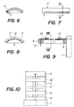
- Fig. 6 similarly shows a guide of the wire in a groove at the edge of the intermediate part of the thread guide, while the Fig. 7 shows a part of such a wire guide 6 ', in side view.
- Figures 8, 9 and 10 relate to an embodiment of a wire guide allowing the winding on a magnetic circuit having an air gap of minimum length.
- the intermediate part 11 ′ can, in this embodiment, have a height substantially equal to the thickness of the wire 10, this last pass through an 11 "opening throughout the game intermediate 11 '.
- Wire 10 is guided upstream and downstream of the intermediate part by parts 21 and 22 cooperating with the wire entry and exit parts, 8 'and 9'.
- Fig. 10 represents this thread guide in top view, analogous parts being designated by the same reference numbers as in the Figures 8, 9 and 1 to 3.
- Fig. 11 shows a device for simultaneously carrying out two coils, 3 and 3 ', on parallel branches of a circuit magnetic 1 whose air gap is in a plane of symmetry between the two coils.
- the thread guides 6 and 61 have one of the shapes described above and are driven in rotation, respectively, around the axes 4 and 4 ′ of the coils to be formed. This rotation takes place at the same speed, in the same direction or opposite direction, but with an angular offset of 180 ° when passage in the air gap, so that the wire guides 6 and 61 pass alternately in the air gap 2.
- the respective supports 7 and 71 and the support 1a of circuit 1 are further arranged to perform a relative movement in the axial direction of the coils.
- Fig. 12 shows, in front view, the shape that the supports can have 7 and 71 to allow the aforementioned rotations in opposition phase. Such a device makes it possible to reduce by approximately half the total winding time.
- the present device can also be adapted to the production of coils on magnetic circuits of toroidal shape, the air gap of which may have a relatively short length.
- a wire guide 62 is arranged with its intermediate part in the air gap 32 of a magnetic circuit 31 to form at least one coil 33 on this circuit, similarly to the case of a circuit with rectilinear branches. In this case, however, the wire guide 62 also performs a pivoting movement in the plane of the circuit 31 around the center of the air gap 32.
- a second coil, not shown, can also be formed on a diametrically opposite portion of the circuit 31, similarly to that illustrated in FIG. 11. Two extreme positions of the wire guide 62 are shown in FIG. 13 and designated by 62a and 62b.
- the arrows f 1 , f 2 and f 3 indicate the different components of the movement of this thread guide relative to the circuit 31.
- the device according to the invention allows coils to be formed at a very high rate in a mass production, so that the cost price of the manufactured part can be lowered considerably compared to that of currently available processes. It can in particular be used in the manufacture of electromagnets, leakage current or voltage transformers, current using a Hall cell placed in the air gap, solenoid valves, relays, contactors or actuators linear or angular.
Landscapes
- Engineering & Computer Science (AREA)
- Power Engineering (AREA)
- Manufacturing & Machinery (AREA)
- Manufacturing Cores, Coils, And Magnets (AREA)
- Coils Or Transformers For Communication (AREA)
- Electromagnets (AREA)
Description
Claims (7)
- Dispositif de bobinage pour former une bobine électrique essentiellement cylindrique (3) sur au moins une branche sensiblement rectiligne d'un circuit magnétique (1) présentant un entrefer (2), ce dispositif comportant au moins un guide-fil rigide (6) comprenant une partie d'entrée (8) et une partie de sortie (9) du fil (10) ainsi qu'une partie intermédiaire allongée (11), cette partie intermédiaire ayant des dimensions permettant le passage de cette partie intermédiaire dans l'entrefer, ce dispositif comportant en outre un dispositif de support (7) dudit guide-fil (6) et un dispositif de support (1a) du circuit magnétique (1), agencés de façon à faire effectuer au guide-fil (6) et au circuit magnétique (1), l'un par rapport à l'autre, un mouvement de rotation autour de l'axe (4) de la bobine (3) et un mouvement de va-et-vient dans le sens axial de la bobine (3), caractérisé en ce que ledit entrefer (2) a une très faible longueur par rapport à la longueur du circuit magnétique (1) et s'étend, perpendiculairement à la direction de sa longueur, essentiellement parallèlement à la branche sur laquelle la bobine (3) est formée, et en ce que ladite partie intermédiaire (11) du guide-fil (6) a, en section longitudinale, sur une longueur au moins égale à celle de la bobine (3), une hauteur inférieure à la longueur de l'entrefer (2), et est disposée parallèlement à l'axe (4) de la bobine (3) à une distance égale à la distance de l'entrefer (2) par rapport à cet axe (4), de manière à permettre le passage de cette partie intermédiaire (11) dans l'entrefer (2) dans le sens longitudinal et dans le sens transversal.
- Dispositif selon la revendication 1, caractérisé en ce que le dispositif de support (7) du guide-fil (6) comporte un support pour une canette (12) d'alimentation en fil agencé de façon que l'axe (4) de rotation de la canette (12) et l'axe (4) de la bobine (3) soient alignées.
- Dispositif selon la revendication 1, caractérisé en ce que la partie intermédiaire (11) du guide-fil (6) a une section transversale délimitée par deux arcs de cercle concentriques ayant leur centre sur la ligne de l'axe (4) de la bobine (3) et étant espacés d'une distance inférieure à la longueur de l'entrefer, et qu'elle comporte un canal ou une rainure pour le guidage du fil (10) parallèlement à l'axe (4) de la bobine (3).
- Dispositif selon la revendication 1, caractérisé en ce que la partie intermédiaire (11) du guide-fil a une section transversale délimitée par deux arcs de cercle concentriques ayant leur centre sur la ligne de l'axe (4) de la bobine (3) et étant espacés d'une distance inférieure à la longueur de l'entrefer, et qu'elle comporte, dans le sens longitudinal, une partie ouverte (11") d'une longueur au moins égale à celle de la bobine (3), les parties d'entrée (8') et de sortie (9') du fil (10) étant agencées pour guider le fil (10) de façon qu'il passe, dans cette partie ouverte, à l'intérieur de l'espace défini par lesdits arcs de cercle.
- Dispositif selon la revendication 1, caractérisé en ce que le support (7) du guide-fil (6) et/ou celui (1a) du circuit magnétique (1) comportent des moyens pour la mise en place du guide-fil (6) avant le bobinage par un déplacement relatif du guide-fil (6) et du circuit magnétique (1) dans le sens axial de la bobine (3), de telle façon que le guide-fil (6) reste, lors de ce déplacement, entièrement à l'extérieur de l'entrefer (2).
- Dispositif selon l'une des revendications 1 à 5, pour former simultanément une seconde bobine (3') essentiellement cylindrique sur une seconde branche sensiblement rectiligne du circuit magnétique (1), les deux branches sur lesquelles sont formées lesdites bobines étant symétriques par rapport à un plan passant par le milieu de l'entrefer (2), perpendiculairement à la direction de la longueur de l'entrefer, caractérisé en ce qu'il comporte un second guide-fil (61) comprenant une partie d'entrée et une partie de sortie de fil ainsi qu'une partie intermédiaire allongée, disposée parallèlement à l'axe (4') de la seconde bobine (3') à une distance égale à la distance de l'entrefer par rapport à cet axe, ladite partie intermédiaire du second guide-fil (61) ayant des dimensions permettant le passage de cette partie intermédiaire dans l'entrefer (2) dans le sens longitudinal et dans le sens transversal de celui-ci, ce dispositif comportant en outre un second dispositif de support (71) pour ledit second guide-fil (61), ce second dispositif de support et le dispositif de support (1a) du circuit magnétique (1) étant agencés de façon à faire effectuer à ce second guide-fil (61) et au circuit magnétique (1), l'un par rapport à l'autre, un mouvement de rotation autour de l'axe (4') de la seconde bobine (3') et un mouvement de va-et-vient dans le sens axial de cette seconde bobine, ledit mouvement de rotation du second guide-fil (61) s'effectuant à la même vitesse que celui du premier guide-fil (6), mais avec un décalage angulaire de 180° lors du passage dans l'entrefer (2).
- Dispositif de bobinage pour former une bobine électrique (33) sur un circuit magnétique (31), ce dispositif comportant au moins un guide-fil rigide (62) comprenant une partie d'entrée et une partie de sortie du fil (10) ainsi qu'une partie intermédiaire allongée ayant des dimensions permettant le passage de cette partie intermédiaire dans l'entrefer (32), ce dispositif comportant en outre un dispositif de support dudit guide-fil (62) et un dispositif de support du circuit magnétique (31), agencés de façon à faire effectuer au guide-fil (62) et au circuit magnétique (31), l'un par rapport à l'autre, un mouvement de rotation autour de l'axe instantané de la bobine (33), ainsi qu'un mouvement de pivotement, dans le plan du circuit magnétique, autour du centre de l'entrefer (32), caractérisé en ce que le circuit magnétique (31) est de forme toroïdale et ledit entrefer (32) a une très faible longueur par rapport à la longueur du circuit magnétique, en ce que la partie intermédiaire du guide-fil (62) a, section transversale, une hauteur telle que cette partie intermédiaire puisse tourner, en passant dans l'entrefer (32) dans le plan du circuit magnétique (31), d'un angle au moins égal à l'angle formé par deux plans déterminés par les extrémités de la bobine (33) à former, et en ce que ledit dispositif de support du guide-fil (62) et ledit dispositif de support du circuit magnétique (31) sont agencés de façon à faire effectuer au guide-fil (62), par rapport au circuit magnétique (31), un mouvement alternatif de translation dans le sens de la longueur de sa partie intermédiaire.
Applications Claiming Priority (4)
| Application Number | Priority Date | Filing Date | Title |
|---|---|---|---|
| CH226695 | 1995-08-04 | ||
| CH02266/95A CH690474A5 (fr) | 1995-08-04 | 1995-08-04 | Dispositif de bobinage pour former une bobine électrique sur un circuit magnétique à entrefer. |
| CH2266/95 | 1995-08-04 | ||
| PCT/CH1996/000264 WO1997006540A1 (fr) | 1995-08-04 | 1996-07-19 | Dispositif de bobinage pour former une bobine electrique sur un circuit magnetique a entrefer |
Publications (2)
| Publication Number | Publication Date |
|---|---|
| EP0842519A1 EP0842519A1 (fr) | 1998-05-20 |
| EP0842519B1 true EP0842519B1 (fr) | 1999-09-08 |
Family
ID=4229751
Family Applications (1)
| Application Number | Title | Priority Date | Filing Date |
|---|---|---|---|
| EP96921862A Expired - Lifetime EP0842519B1 (fr) | 1995-08-04 | 1996-07-19 | Dispositif de bobinage pour former une bobine electrique sur un circuit magnetique a entrefer |
Country Status (7)
| Country | Link |
|---|---|
| US (1) | US5709353A (fr) |
| EP (1) | EP0842519B1 (fr) |
| JP (1) | JP3007420B2 (fr) |
| AT (1) | ATE184420T1 (fr) |
| CH (1) | CH690474A5 (fr) |
| DE (1) | DE69604184T2 (fr) |
| WO (1) | WO1997006540A1 (fr) |
Families Citing this family (2)
| Publication number | Priority date | Publication date | Assignee | Title |
|---|---|---|---|---|
| US6512438B1 (en) | 1999-12-16 | 2003-01-28 | Honeywell International Inc. | Inductor core-coil assembly and manufacturing thereof |
| US6948676B1 (en) | 2004-07-06 | 2005-09-27 | Tremblay John K | Method of winding electrical and electronic components |
Family Cites Families (9)
| Publication number | Priority date | Publication date | Assignee | Title |
|---|---|---|---|---|
| US2777116A (en) * | 1952-05-13 | 1957-01-08 | Bendix Aviat Corp | Coil form |
| US2773651A (en) * | 1952-11-13 | 1956-12-11 | Western Electric Co | Coil winding apparatus |
| US3128056A (en) * | 1962-03-02 | 1964-04-07 | Universal Mfg Co | Machine for winding toroidal television vertical deflection coils |
| US4417699A (en) * | 1981-11-19 | 1983-11-29 | Alfred Skrobisch | Apparatus for winding a wire or thread on C-shaped cores |
| US4529138A (en) * | 1983-08-29 | 1985-07-16 | Westinghouse Electric Corp. | Strip core winder for core-coil assembly |
| EP0188095A1 (fr) * | 1984-12-13 | 1986-07-23 | East Rock Technology Inc. | Procédé pour la fabrication d'un ballast inductif toroidal et machine utilisant ce procédé |
| US4782582A (en) * | 1984-12-13 | 1988-11-08 | Eastrock Technology Inc. | Process for the manufacture of a toroidal ballast choke |
| DE3635220A1 (de) * | 1986-10-16 | 1988-04-21 | Standard Elektrik Lorenz Ag | Wickelvorrichtung |
| US5032846A (en) * | 1989-09-05 | 1991-07-16 | Chang Yu Pin | Selectively positionable antenna mounting |
-
1995
- 1995-08-04 CH CH02266/95A patent/CH690474A5/fr not_active IP Right Cessation
-
1996
- 1996-07-19 WO PCT/CH1996/000264 patent/WO1997006540A1/fr not_active Ceased
- 1996-07-19 DE DE69604184T patent/DE69604184T2/de not_active Expired - Fee Related
- 1996-07-19 AT AT96921862T patent/ATE184420T1/de not_active IP Right Cessation
- 1996-07-19 JP JP9507990A patent/JP3007420B2/ja not_active Expired - Fee Related
- 1996-07-19 EP EP96921862A patent/EP0842519B1/fr not_active Expired - Lifetime
- 1996-08-02 US US08/691,688 patent/US5709353A/en not_active Expired - Fee Related
Also Published As
| Publication number | Publication date |
|---|---|
| US5709353A (en) | 1998-01-20 |
| DE69604184D1 (de) | 1999-10-14 |
| WO1997006540A1 (fr) | 1997-02-20 |
| EP0842519A1 (fr) | 1998-05-20 |
| JPH11505072A (ja) | 1999-05-11 |
| DE69604184T2 (de) | 2000-06-15 |
| JP3007420B2 (ja) | 2000-02-07 |
| ATE184420T1 (de) | 1999-09-15 |
| CH690474A5 (fr) | 2000-09-15 |
Similar Documents
| Publication | Publication Date | Title |
|---|---|---|
| EP0429599A1 (fr) | Actionneur electromagnetique monophase de faible encombrement. | |
| EP0429625A1 (fr) | Actionneur electromagnetique monophase de faible encombrement. | |
| EP0584295B1 (fr) | Procede de montage d'une bobine electrique sur un circuit magnetique a entrefer | |
| FR2464125A1 (fr) | Bloc magnetique a aimants permanents et a dispositif mecanique de commande marche-arret | |
| FR2930689A1 (fr) | Machine tournante a flux transverse et dispositif de commutation equipe d'une telle machine | |
| FR2562025A1 (fr) | Derailleur avant, notamment pour une bicyclette | |
| WO1997038932A1 (fr) | Dispositif tendeur de fil et materiel textile equipe d'un tel dispositif | |
| FR2541224A1 (fr) | Derailleur pour une bicyclette | |
| CH690474A5 (fr) | Dispositif de bobinage pour former une bobine électrique sur un circuit magnétique à entrefer. | |
| CH676647A5 (fr) | ||
| CA1282289C (fr) | Dispositif et procede pour assembler des fils; assemblages de filsobtenus avec ce dispositif et ce procede | |
| FR2877135A1 (fr) | Dispositif et procede de roulage de bobine de fil rigide autour d'un anneau | |
| FR2481019A1 (fr) | Moteur pas a pas notamment pour montre electronique | |
| FR2836755A1 (fr) | Actionneur electromagnetique a force d'attraction controlee | |
| EP1554209B1 (fr) | Dispositif de renvidage d'un fil sur un support entraine en rotation | |
| EP0090881B1 (fr) | Ligature pour la retenue d'un câble électrique dans la gorge supérieure d'un isolateur rigide | |
| FR2584247A1 (fr) | Induit tournant d'un servomoteur electrique muni de pieces polaires en forme de coin | |
| FR2957713A1 (fr) | Actionneur lineaire electromagnetique | |
| EP0409743A1 (fr) | Dispositif tendeur de fil pour machines textiles | |
| EP1612812B1 (fr) | Actionneur linéaire à prise directe | |
| FR2793597A1 (fr) | Dispositif de commande de position de type electromagnetique | |
| FR2831121A1 (fr) | Systeme de passage d'un cable a travers un volant mobile | |
| EP0551787A1 (fr) | Machine pour la réalisation de fils guipés | |
| FR2471657A1 (fr) | Dispositif d'actionnement electromagnetique | |
| FR2669766A1 (fr) | Inductance, notamment pour ondes courtes. |
Legal Events
| Date | Code | Title | Description |
|---|---|---|---|
| PUAI | Public reference made under article 153(3) epc to a published international application that has entered the european phase |
Free format text: ORIGINAL CODE: 0009012 |
|
| 17P | Request for examination filed |
Effective date: 19971205 |
|
| AK | Designated contracting states |
Kind code of ref document: A1 Designated state(s): AT BE CH DE DK ES FI FR GB GR IE IT LI LU MC NL PT SE |
|
| GRAG | Despatch of communication of intention to grant |
Free format text: ORIGINAL CODE: EPIDOS AGRA |
|
| 17Q | First examination report despatched |
Effective date: 19981230 |
|
| GRAG | Despatch of communication of intention to grant |
Free format text: ORIGINAL CODE: EPIDOS AGRA |
|
| GRAH | Despatch of communication of intention to grant a patent |
Free format text: ORIGINAL CODE: EPIDOS IGRA |
|
| GRAH | Despatch of communication of intention to grant a patent |
Free format text: ORIGINAL CODE: EPIDOS IGRA |
|
| GRAA | (expected) grant |
Free format text: ORIGINAL CODE: 0009210 |
|
| AK | Designated contracting states |
Kind code of ref document: B1 Designated state(s): AT BE CH DE DK ES FI FR GB GR IE IT LI LU MC NL PT SE |
|
| PG25 | Lapsed in a contracting state [announced via postgrant information from national office to epo] |
Ref country code: SE Free format text: THE PATENT HAS BEEN ANNULLED BY A DECISION OF A NATIONAL AUTHORITY Effective date: 19990908 Ref country code: NL Free format text: LAPSE BECAUSE OF FAILURE TO SUBMIT A TRANSLATION OF THE DESCRIPTION OR TO PAY THE FEE WITHIN THE PRESCRIBED TIME-LIMIT Effective date: 19990908 Ref country code: IT Free format text: LAPSE BECAUSE OF FAILURE TO SUBMIT A TRANSLATION OF THE DESCRIPTION OR TO PAY THE FEE WITHIN THE PRE;WARNING: LAPSES OF ITALIAN PATENTS WITH EFFECTIVE DATE BEFORE 2007 MAY HAVE OCCURRED AT ANY TIME BEFORE 2007. THE CORRECT EFFECTIVE DATE MAY BE DIFFERENT FROM THE ONE RECORDED.SCRIBED TIME-LIMIT Effective date: 19990908 Ref country code: GR Free format text: LAPSE BECAUSE OF NON-PAYMENT OF DUE FEES Effective date: 19990908 Ref country code: FI Free format text: LAPSE BECAUSE OF NON-PAYMENT OF DUE FEES Effective date: 19990908 Ref country code: ES Free format text: THE PATENT HAS BEEN ANNULLED BY A DECISION OF A NATIONAL AUTHORITY Effective date: 19990908 Ref country code: AT Free format text: LAPSE BECAUSE OF FAILURE TO SUBMIT A TRANSLATION OF THE DESCRIPTION OR TO PAY THE FEE WITHIN THE PRESCRIBED TIME-LIMIT Effective date: 19990908 |
|
| REF | Corresponds to: |
Ref document number: 184420 Country of ref document: AT Date of ref document: 19990915 Kind code of ref document: T |
|
| REG | Reference to a national code |
Ref country code: CH Ref legal event code: EP |
|
| REF | Corresponds to: |
Ref document number: 69604184 Country of ref document: DE Date of ref document: 19991014 |
|
| REG | Reference to a national code |
Ref country code: CH Ref legal event code: NV Representative=s name: WILLIAM BLANC & CIE CONSEILS EN PROPRIETE INDUSTRI |
|
| REG | Reference to a national code |
Ref country code: IE Ref legal event code: FG4D Free format text: FRENCH |
|
| PG25 | Lapsed in a contracting state [announced via postgrant information from national office to epo] |
Ref country code: DK Free format text: LAPSE BECAUSE OF FAILURE TO SUBMIT A TRANSLATION OF THE DESCRIPTION OR TO PAY THE FEE WITHIN THE PRESCRIBED TIME-LIMIT Effective date: 19991208 |
|
| PG25 | Lapsed in a contracting state [announced via postgrant information from national office to epo] |
Ref country code: PT Free format text: LAPSE BECAUSE OF FAILURE TO SUBMIT A TRANSLATION OF THE DESCRIPTION OR TO PAY THE FEE WITHIN THE PRESCRIBED TIME-LIMIT Effective date: 19991209 |
|
| GBT | Gb: translation of ep patent filed (gb section 77(6)(a)/1977) |
Effective date: 19991206 |
|
| NLV1 | Nl: lapsed or annulled due to failure to fulfill the requirements of art. 29p and 29m of the patents act | ||
| PLBE | No opposition filed within time limit |
Free format text: ORIGINAL CODE: 0009261 |
|
| STAA | Information on the status of an ep patent application or granted ep patent |
Free format text: STATUS: NO OPPOSITION FILED WITHIN TIME LIMIT |
|
| PG25 | Lapsed in a contracting state [announced via postgrant information from national office to epo] |
Ref country code: LU Free format text: LAPSE BECAUSE OF NON-PAYMENT OF DUE FEES Effective date: 20000719 |
|
| PG25 | Lapsed in a contracting state [announced via postgrant information from national office to epo] |
Ref country code: MC Free format text: THE PATENT HAS BEEN ANNULLED BY A DECISION OF A NATIONAL AUTHORITY Effective date: 20000731 Ref country code: BE Free format text: LAPSE BECAUSE OF NON-PAYMENT OF DUE FEES Effective date: 20000731 |
|
| PG25 | Lapsed in a contracting state [announced via postgrant information from national office to epo] |
Ref country code: IE Free format text: LAPSE BECAUSE OF NON-PAYMENT OF DUE FEES Effective date: 20000816 |
|
| 26N | No opposition filed | ||
| REG | Reference to a national code |
Ref country code: IE Ref legal event code: FD4D |
|
| BERE | Be: lapsed |
Owner name: S.A. LIAISONS ELECTRONIQUES-MECANIQUES LEM Effective date: 20000731 |
|
| REG | Reference to a national code |
Ref country code: GB Ref legal event code: IF02 |
|
| REG | Reference to a national code |
Ref country code: CH Ref legal event code: NV Representative=s name: REUTELER & CIE SA |
|
| PGFP | Annual fee paid to national office [announced via postgrant information from national office to epo] |
Ref country code: CH Payment date: 20070718 Year of fee payment: 12 |
|
| PGFP | Annual fee paid to national office [announced via postgrant information from national office to epo] |
Ref country code: GB Payment date: 20070720 Year of fee payment: 12 |
|
| PGFP | Annual fee paid to national office [announced via postgrant information from national office to epo] |
Ref country code: FR Payment date: 20070710 Year of fee payment: 12 |
|
| PGFP | Annual fee paid to national office [announced via postgrant information from national office to epo] |
Ref country code: DE Payment date: 20080722 Year of fee payment: 13 |
|
| REG | Reference to a national code |
Ref country code: CH Ref legal event code: PL |
|
| GBPC | Gb: european patent ceased through non-payment of renewal fee |
Effective date: 20080719 |
|
| REG | Reference to a national code |
Ref country code: FR Ref legal event code: ST Effective date: 20090331 |
|
| PG25 | Lapsed in a contracting state [announced via postgrant information from national office to epo] |
Ref country code: LI Free format text: LAPSE BECAUSE OF NON-PAYMENT OF DUE FEES Effective date: 20080731 Ref country code: GB Free format text: LAPSE BECAUSE OF NON-PAYMENT OF DUE FEES Effective date: 20080719 Ref country code: CH Free format text: LAPSE BECAUSE OF NON-PAYMENT OF DUE FEES Effective date: 20080731 |
|
| PG25 | Lapsed in a contracting state [announced via postgrant information from national office to epo] |
Ref country code: FR Free format text: LAPSE BECAUSE OF NON-PAYMENT OF DUE FEES Effective date: 20080731 |
|
| PG25 | Lapsed in a contracting state [announced via postgrant information from national office to epo] |
Ref country code: DE Free format text: LAPSE BECAUSE OF NON-PAYMENT OF DUE FEES Effective date: 20100202 |