EP0841467A1 - Gesteinsfräskopf - Google Patents
Gesteinsfräskopf Download PDFInfo
- Publication number
- EP0841467A1 EP0841467A1 EP97118802A EP97118802A EP0841467A1 EP 0841467 A1 EP0841467 A1 EP 0841467A1 EP 97118802 A EP97118802 A EP 97118802A EP 97118802 A EP97118802 A EP 97118802A EP 0841467 A1 EP0841467 A1 EP 0841467A1
- Authority
- EP
- European Patent Office
- Prior art keywords
- housing
- gear
- drive
- milling head
- rock
- Prior art date
- Legal status (The legal status is an assumption and is not a legal conclusion. Google has not performed a legal analysis and makes no representation as to the accuracy of the status listed.)
- Granted
Links
- 239000011435 rock Substances 0.000 title claims abstract description 22
- 238000003801 milling Methods 0.000 title claims description 41
- 229910000831 Steel Inorganic materials 0.000 claims abstract description 3
- 239000010959 steel Substances 0.000 claims abstract description 3
- 230000005540 biological transmission Effects 0.000 claims description 3
- 230000001681 protective effect Effects 0.000 claims description 2
- 229910001208 Crucible steel Inorganic materials 0.000 claims 1
- 238000005520 cutting process Methods 0.000 abstract description 11
- ZZUFCTLCJUWOSV-UHFFFAOYSA-N furosemide Chemical compound C1=C(Cl)C(S(=O)(=O)N)=CC(C(O)=O)=C1NCC1=CC=CO1 ZZUFCTLCJUWOSV-UHFFFAOYSA-N 0.000 abstract 1
- 238000010276 construction Methods 0.000 description 7
- 230000008439 repair process Effects 0.000 description 4
- 230000005641 tunneling Effects 0.000 description 3
- 238000005065 mining Methods 0.000 description 2
- 230000002028 premature Effects 0.000 description 2
- 238000009412 basement excavation Methods 0.000 description 1
- 238000005538 encapsulation Methods 0.000 description 1
- 238000000605 extraction Methods 0.000 description 1
- 239000000463 material Substances 0.000 description 1
Images



Classifications
-
- E—FIXED CONSTRUCTIONS
- E21—EARTH OR ROCK DRILLING; MINING
- E21D—SHAFTS; TUNNELS; GALLERIES; LARGE UNDERGROUND CHAMBERS
- E21D9/00—Tunnels or galleries, with or without linings; Methods or apparatus for making thereof; Layout of tunnels or galleries
- E21D9/10—Making by using boring or cutting machines
- E21D9/1006—Making by using boring or cutting machines with rotary cutting tools
- E21D9/1013—Making by using boring or cutting machines with rotary cutting tools on a tool-carrier supported by a movable boom
- E21D9/102—Making by using boring or cutting machines with rotary cutting tools on a tool-carrier supported by a movable boom by a longitudinally extending boom being pivotable about a vertical and a transverse axis
- E21D9/1026—Making by using boring or cutting machines with rotary cutting tools on a tool-carrier supported by a movable boom by a longitudinally extending boom being pivotable about a vertical and a transverse axis the tool-carrier being rotated about a transverse axis
-
- E—FIXED CONSTRUCTIONS
- E02—HYDRAULIC ENGINEERING; FOUNDATIONS; SOIL SHIFTING
- E02F—DREDGING; SOIL-SHIFTING
- E02F3/00—Dredgers; Soil-shifting machines
- E02F3/04—Dredgers; Soil-shifting machines mechanically-driven
- E02F3/18—Dredgers; Soil-shifting machines mechanically-driven with digging wheels turning round an axis, e.g. bucket-type wheels
- E02F3/20—Dredgers; Soil-shifting machines mechanically-driven with digging wheels turning round an axis, e.g. bucket-type wheels with tools that only loosen the material, i.e. mill-type wheels
- E02F3/205—Dredgers; Soil-shifting machines mechanically-driven with digging wheels turning round an axis, e.g. bucket-type wheels with tools that only loosen the material, i.e. mill-type wheels with a pair of digging wheels, e.g. slotting machines
-
- E—FIXED CONSTRUCTIONS
- E21—EARTH OR ROCK DRILLING; MINING
- E21D—SHAFTS; TUNNELS; GALLERIES; LARGE UNDERGROUND CHAMBERS
- E21D9/00—Tunnels or galleries, with or without linings; Methods or apparatus for making thereof; Layout of tunnels or galleries
- E21D9/10—Making by using boring or cutting machines
- E21D9/1086—Drives or transmissions specially adapted therefor
Definitions
- the invention relates to a rock milling head according to the preamble of the claim 1.
- Such a rock milling head is known from DE 33 16 840 A1.
- This Document describes a rock milling head with a housing that can be attached to a cantilever or support arm connection, it being known here directly or indirectly with the rotary drive in the rear section of the housing connected to store a drive pinion. The case is in the back Section completed by a plate.
- As a gear connection between The drive pinion and drive spur gear are idler gears mounted in the housing intended. It follows from this document that in front section of the housing with a central drive spur gear connected shafts of the two milling drums in the outer bearing hubs of the Housing are stored. This construction is relatively complex and prone to wear.
- the housing of a drive arrangement is known from DB 38 20 264 A1 for the cutting heads or rollers of a tunneling or extraction machine to be made in one piece from steel.
- Rock milling are known for the rest of the tunnel and mining industry where they as adapted to the respective conditions on site, usually with only one rotating Milling head equipped excavation or mining equipment used will. There are also cutting heads with two milling drums known for heavy universal excavator used in the attachment change to digging tools will.
- a rock milling head is now created in which the exchangeability of parts during repair work, and which ones also has a robust and compact overall structure.
- the proposed design creates a rock milling head, the Coaxial milling drums on the boom / support arm with a center in between arranged slim gear housing are supported by the large-scale milling work not or only to a negligible extent hindered will. Since the housing is only the one running in a line Pick up gear train from three gears in a row needs, it can be one-piece, narrow or space-saving and torsion-resistant be carried out. Both through the rigidity of the case as well due to the small number of gears housed in it, which act as spur gears can be carried out, there is a risk of premature gear wear largely eliminated. In addition, the simple gear links Almost assembled, accessible and replaceable in the housing.
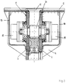
- the gear housing 1 consists of a one-piece Welded construction, the rear access opening through a releasable mounting cover 11 is closed.
- the welded construction includes two essentially the same, spaced according to the width of the gear toothed wheels housed in the housing are arranged relative to one another Side plates 2 and their edges connecting surrounding walls 4, the approximately over half the length of the housing starting from the rear section of the housing in at least the circumference of the intermediate gear 22 certain distance parallel to each other and then in each other tapered course around a rounded front end of the housing are.
- the side plates 2 can be rounded in the area of the tapered front end of the housing through a correspondingly bent intermediate piece 3 be connected to each other, which continues the straight surrounding walls 4.
- At the rear end of the housing 1 is a widened connection plate 5 attached, the one indicated in Fig. 2 connection bracket 6 of the boom or support arm opposite and one of the cross section of the housing Contains 1 corresponding opening.
- bearing hubs at the front end of the housing 7 welded for a drum shaft 21, for each milling drum a shaft portion and a reinforced one formed as a drive spur gear 21a Includes middle section.
- the rear housing section are on the side plates bearing hubs 8 and 9 for a drive pinion 20 Welded shaft 20a.
- the surrounding walls 4 are in accordance with FIG. 1 in the rear area the housing 1 widened on both sides and there for mutual stiffening connected to the connection plate 5, together with a mudguard 10 a cover for the level of the drive pinion 20 on the outside Side plates 2 connected drive means, e.g. Form engine 18.
- the housing type described above can be used for a Cast part can be taken directly, but without the surrounding walls 4 must be designed as a widened protective cover.
- a hydraulic radial piston motor is attached to the bearing hub 9 18 flanged with the one supported on tapered roller bearings 34
- Shaft 20a of the drive pinion 20 is in drive connection.
- the bearing hub 8 and the side plate 2 carrying them contain sufficiently large openings for inserting the drive pinion 20 and for receiving a tapered roller bearing 34.
- the bearing hub 8 is by a screw-on mounting cover 36 closed.
- the opposite part of the shaft 20a is over an annular collar and a shaft seal in an opening of the left in Fig. 1 Sealed side plate 2 and with a reduced diameter End section in a tapered roller bearing accommodated in the bearing hub 9 34 protected.
- the tapered roller bearings used in this embodiment 34 take the due to the control play of the radial piston engine 18 occurring axial forces.
- the larger idler gear 22 of the reduction gear is put together with pre-assembled roller bearings 12 through the rear opening in the Housing 1 inserted and with this on a through mounting holes in the side plates 2 inserted bearing pin 13 mounted.
- the bearing pin 13 is supported with a reinforced end collar 38 in the right side plate 2 and at the opposite end through a mounting hole closing lid 14 fixed.
- the intermediate gear 22 is both with the drive pinion 20 and the spur gear 21a of the drum shaft 21 in Intervention.
- the drum shaft 21 with its unitary central drive spur gear 21a is by the bearing hubs 7 and in their continuation in the side plates 2 contained openings inserted into the housing 1 and by means of tapered roller bearings 17 supported.
- For fixed positioning of the drum shaft 21 serve outside with the bearing hubs 7 screwed bearing caps 15, in which Shaft seals 16 are provided.
- the milling drums 25 are each on a spline toothing 23 of the outer drum shaft sections attached and with the help of retaining rings 24 and screwed Caps 26 positioned.
- Dispensing with planetary gears can be a variety of drive motors with different speeds and torques by one to three-stage planetary gear can be adapted to the milling requirements.
Landscapes
- Engineering & Computer Science (AREA)
- Mining & Mineral Resources (AREA)
- Environmental & Geological Engineering (AREA)
- Life Sciences & Earth Sciences (AREA)
- General Life Sciences & Earth Sciences (AREA)
- Geochemistry & Mineralogy (AREA)
- Geology (AREA)
- Civil Engineering (AREA)
- Mechanical Engineering (AREA)
- General Engineering & Computer Science (AREA)
- Structural Engineering (AREA)
- Earth Drilling (AREA)
- Drilling And Exploitation, And Mining Machines And Methods (AREA)
- Excavating Of Shafts Or Tunnels (AREA)
- Crushing And Grinding (AREA)
- Shovels (AREA)
Abstract
Description
- Fig. 1
- einen Längsschnitt durch einen Schneidkopf gemäß der Erfindung, der durch einen einzelnen hydraulischen Hochmoment-Motor, z.B. Radialkolbenmotor angetrieben ist,
- Fig. 2
- eine Seitenansicht des als einteilige Schweißkonstruktion ausgeführten Getriebegehäuses, in der mögliche Frästrommeldurchmesser und eine Ausleger-Anschlußkonsole mit unterbrochenen Linien dargestellt sind,
- Fig. 3
- einen senkrechten Teilschnitt durch einen Schneidkopf gemäß der Erfindung mit zwei gleichen auf das Antriebsritzel wirkenden hydraulischen Mittelmoment-Motoren z.B. Flügelzellenmotoren, und
- Fig. 4
- einen vertikalen Teilschnitt durch eine andere Ausführungsform eines Schneidkopfes gemäß der Erfindung mit einem hochtourig drehenden Hydraulikmotor z.B. der Zahnrad- oder Axialkolbenbauart, der durch einen mit unterbrochenen Linien eingezeichneten Elektromotor ersetzt werden kann.
Claims (8)
- Gesteinsfräskopf mit einem an einem Ausleger- oder Tragarmanschluß eines Arbeitsgerätes anbaubaren Gehäuse, in dein ein mit einem Drehantrieb in Verbindung stehendes Zahnrad-Untersetzungsgetriebe für zwei auf axial zueinander ausgerichteten Wellen drehende gleiche Frästrommeln gelagert und gekapselt ist, wobei im hinteren Abschnitt des Gehäuses ein direkt oder mittelbar mit dem Drehantrieb verbundenes Antriebsritzel gelagert und das Gehäuse durch eine Anschlußplatte zum Tragarm hin abgeschlossen und bis zu einem auf gegenüberliegenden Seiten mit äußeren Lagernaben versehenen vorderen Abschnitt verlängert ist, in denen die mit einem mittleren Antriebsstirnrad einheitlich verbundenen Wellen der beiden Frästrommeln gelagert sind,
dadurch gekennzeichnet,
daß der Ausleger/Tragarm (4a) als zwischen den gleichachsigen Frästrommeln verlaufendes, schlankes, einteiliges Getriebegehäuse aus Stahl oder Stahlguß ausgebildet ist, in dem drei in einer Linie hintereinander angeordnete Zahnräder vorgesehen sind, daß als Getriebeverbindung zwischen Antriebsritzel (20) und Antriebsstirnrad (21a) ein einen größeren Durchmesser gegenüber den beiden Zahnrädern (20, 21a) aufweisendes Zwischenrad (22) vorgesehen ist, daß die Anschlußplatte (5) gegenüber dem Gehäuse (4a) breiter ausgebildet ist, und daß die Getriebeteile in an sich bekannter Weise über im Gehäuse vorgesehene und über Deckel (8a, 11, 14) verschließbare Öffnungen aus- und einbaubar sind. - Gesteinsfräskopf nach Anspruch 1, dadurch gekennzeichnet, daß das Gehäuse (1) zwei im Abstand entsprechend der Breite der Getriebe-Zahnräder (20, 21a, 22) zueinander angeordnete Seitenplatten oder -wände (2) sowie deren Ränder verbindende Umfassungswände (3, 4) aufweist, die am hinteren Gehäuseabschnitt in einem durch den Umfang des Zwischenrades (22) bestimmten Mindestabstand zueinander parallel verlaufen und im Bereich des vorderen Gehäuseabschnittes in zueinander verjüngendern Verlauf an das etwa dem Umfang der äußeren Lagernaben (7) angepaßte vordere Gehäuseende angeschlossen sind.
- Gesteinsfräskopf nach Anspruch 1 oder 2, dadurch gekennzeichnet, daß sämtliche Zahnräder des Untersetzungsgetriebes einschließlich jeweils zugeordneter Lager und Lagerzapfen oder -wellen in den einteiligen Gehäusekörper durch jeweils zugeordnete in den Seitenwänden und in der rückwärtigen Anschlußplatte enthaltene, mittels Deckeln (8a, 11, 14) verschließbare Öffnungen einführbar und montierbar sind.
- Gesteinsfräskopf nach Anspruch 3, dadurch gekennzeichnet, daß das Zwischenrad (22) zusammen mit im Zwischenradkörper vormontierten Lagermitteln (12) durch die Öffnung der Anschlußplatte (5) in das Gehäuse (1) einschiebbar ist, wobei ein die Lagermittel abstützender Lagerzapfen (13) durch eine der Seitenplattenöffnung einführbar und in dieser mittels eines Verschlußdeckels (14) fixierbar ist.
- Gesteinsfräskopf nach einem der vorhergehenden Ansprüche, dadurch gckennzeichnet, daß die Umfassungswände (4) etwa im Bereich des hinteren Gehäuseabschnittes beidseitig über die Gehäusebreite hinausragen und sowohl zur Versteifung mit der Anschlußplatte (5) verbunden als auch als Schutzabdeckung für in Höhe des Antriebsritzels außen am Gehäuse angeschlossene Antriebsmittel (10; 19; 31, 32) ausgebildet sind.
- Gesteinsfräskopf nach einem der vorhergehenden Ansprüche, dadurch gekennzeichnet, daß als Antriebsquelle zwei gleiche hydraulische Mittelmoment-Motoren (19) von gegenüberliegenden Seiten des Gehäuses (1) aus an verlängerte Lagerzapfen des Antriebsritzels (20) angeschlossen sind.
- Gesteinsfräskopf nach einem der Ansprüche 1 bis 5, dadurch gekennzeichnet, daß an eine Seite des Gehäuses (1) ein Antriebsmotor (30; 31) und an die gegenüberliegende Seite ein Untersetzungs- insbesondere Planetengetriebe (32) angeflanscht ist, dessen Ausgangsteil bzw. Abtriebs-Planetenträger (33) mit einem Lagerzapfen des Antriebsritzels (20) und dessen Eingangsteil bzw. Sonnenrad (29) über eine durch eine zentrische Bohrung der Antriebsritzelwelle hindurchgeführte Anschlußwelle (28) mit dem Antriebsmotor in Verbindung steht.
- Gesteinsfräskopf nach einem der vorhergehenden Ansprüche, dadurch gekennzeichnet, daß die Frästrommeln (25) jeweils mittels einer zentrischen Bohrung auf die aus am vorderen Gehäuseabschnitt angeordnete Lagernaben (7) herausstehenden Anschlußenden (23) der Welle (21) aufsteckbar und jeweils mittels eines sehraubbaren Verschlußdeckels (26) fixierbar sind.
Applications Claiming Priority (2)
| Application Number | Priority Date | Filing Date | Title |
|---|---|---|---|
| DE19645650A DE19645650C1 (de) | 1996-11-06 | 1996-11-06 | Gesteinsfräskopf |
| DE19645650 | 1996-11-06 |
Publications (2)
| Publication Number | Publication Date |
|---|---|
| EP0841467A1 true EP0841467A1 (de) | 1998-05-13 |
| EP0841467B1 EP0841467B1 (de) | 2000-07-05 |
Family
ID=7810748
Family Applications (1)
| Application Number | Title | Priority Date | Filing Date |
|---|---|---|---|
| EP97118802A Expired - Lifetime EP0841467B1 (de) | 1996-11-06 | 1997-10-29 | Gesteinsfräskopf |
Country Status (5)
| Country | Link |
|---|---|
| US (1) | US6158818A (de) |
| EP (1) | EP0841467B1 (de) |
| JP (1) | JPH10196284A (de) |
| AT (1) | ATE194409T1 (de) |
| DE (2) | DE19645650C1 (de) |
Cited By (3)
| Publication number | Priority date | Publication date | Assignee | Title |
|---|---|---|---|---|
| WO2000075488A1 (de) | 1999-06-08 | 2000-12-14 | Voest-Alpine Bergtechnik Gesellschaft M.B.H. | Gesteinskopf für den anbau an baggerarmen |
| CN102691501A (zh) * | 2012-06-14 | 2012-09-26 | 三一重型装备有限公司 | 一种掘进机及其截割部 |
| WO2020169657A1 (de) * | 2019-02-21 | 2020-08-27 | Liebherr-Components Biberach Gmbh | Fräsradanordnung für eine schlitzwandfräse |
Families Citing this family (14)
| Publication number | Priority date | Publication date | Assignee | Title |
|---|---|---|---|---|
| DE10041275B4 (de) * | 2000-08-23 | 2006-07-27 | Firma Klaus Ertmer Maschinenbautechnologie | Frässystem zum Anbau an hydraulische Trägergeräte |
| ITBO20010632A1 (it) * | 2001-10-16 | 2003-04-16 | Simex Engineering S R L | Fresatrice oleodinamica per macchine escavatrici |
| CN100532784C (zh) * | 2007-03-13 | 2009-08-26 | 郝忠文 | 掘进机的掘进头 |
| DE102011108016A1 (de) * | 2011-07-19 | 2013-01-24 | Liebherr-Components Biberach Gmbh | Selbstfahrender Oberflächenfräser |
| US8864621B2 (en) * | 2012-05-30 | 2014-10-21 | Fairfield Manufacturing Company, Inc. | Roadheader gearbox |
| CN103243755B (zh) * | 2013-05-11 | 2016-02-03 | 山西东华机械有限公司 | 卧底机用轴承加齿圈式转台 |
| EP2821589B1 (de) * | 2013-07-04 | 2015-10-28 | Sandvik Intellectual Property AB | Bergbaumaschinenschneidkopf-Antriebsmontage |
| CN103759049B (zh) * | 2014-01-15 | 2015-12-09 | 常林股份有限公司 | 掘进机截割臂 |
| CN104912568B (zh) * | 2015-06-17 | 2017-07-04 | 唐忠盛 | 高频振动横向铣挖头及具有该铣挖头的铣挖机和掘进机 |
| CN109736826B (zh) * | 2019-01-10 | 2020-08-07 | 河南理工大学 | 一种岩土破掘机用破掘滚筒 |
| US12006824B2 (en) | 2020-11-16 | 2024-06-11 | Joy Global Underground Mining Llc | Cutting assembly for longwall mining system |
| US11761333B2 (en) | 2020-11-16 | 2023-09-19 | Joy Global Underground Mining Llc | Cutting assembly for longwall mining system |
| CN112576270A (zh) * | 2020-12-08 | 2021-03-30 | 李国平 | 一种多马达铣挖机构 |
| CN112901163B (zh) * | 2021-03-22 | 2025-06-10 | 天地上海采掘装备科技有限公司 | 具有良好适应性的分体式破碎机构及其安装结构 |
Citations (8)
| Publication number | Priority date | Publication date | Assignee | Title |
|---|---|---|---|---|
| DE2447604A1 (de) * | 1974-10-05 | 1976-04-08 | Eickhoff Geb | Vortriebsmaschine |
| FR2323001A1 (fr) * | 1975-09-02 | 1977-04-01 | Voest Ag | Haveuse comportant une partie du train demultiplicateur dans chaque tete de havage |
| GB2067232A (en) * | 1979-09-21 | 1981-07-22 | Coal Industry Patents Ltd | Excavating machines |
| DE3316840A1 (de) | 1983-05-07 | 1984-11-08 | Gebr. Eickhoff Maschinenfabrik U. Eisengiesserei Mbh, 4630 Bochum | Teilschnittvortriebsmaschine zum auffahren von strecken |
| GB2189278A (en) * | 1986-04-16 | 1987-10-21 | Voest Alpine Ag | Drive arrangement for the cutting heads of a cutting machine |
| DE3820264A1 (de) | 1987-06-17 | 1989-01-05 | Voest Alpine Ag | Antriebsanordnung fuer die schraemkoepfe oder -walzen einer vortriebs- oder gewinnungsmaschine |
| DE3823762A1 (de) * | 1987-07-15 | 1989-01-26 | Voest Alpine Ag | Motoranordnung fuer den antrieb der abbauwerkzeuge einer streckenvortriebs- und gewinnungsmaschine |
| DE3739110A1 (de) * | 1987-11-19 | 1989-06-01 | Atlas Copco Eickhoff Road | Motorbefestigung fuer teilschnittvortriebsmaschinen |
Family Cites Families (4)
| Publication number | Priority date | Publication date | Assignee | Title |
|---|---|---|---|---|
| BE563234A (de) * | ||||
| DE338730C (de) * | 1921-07-30 | Heinrich Wendschoff | Mittels Ejektors betriebene Staubabsaugevorrichtung fuer Aufbruchbohrhaemmer | |
| DE339235C (de) * | 1916-06-11 | 1922-01-05 | Otto Ohnesorge Dipl Ing | Panzer fuer Luftreifenraeder u. dgl. |
| US5478139A (en) * | 1993-05-25 | 1995-12-26 | Rockmaster Equipment Manufacturing, Inc. | Mobile digging/cutting system |
-
1996
- 1996-11-06 DE DE19645650A patent/DE19645650C1/de not_active Expired - Fee Related
-
1997
- 1997-10-29 DE DE59701966T patent/DE59701966D1/de not_active Expired - Lifetime
- 1997-10-29 AT AT97118802T patent/ATE194409T1/de not_active IP Right Cessation
- 1997-10-29 EP EP97118802A patent/EP0841467B1/de not_active Expired - Lifetime
- 1997-11-05 US US08/964,893 patent/US6158818A/en not_active Expired - Fee Related
- 1997-11-06 JP JP9341825A patent/JPH10196284A/ja active Pending
Patent Citations (8)
| Publication number | Priority date | Publication date | Assignee | Title |
|---|---|---|---|---|
| DE2447604A1 (de) * | 1974-10-05 | 1976-04-08 | Eickhoff Geb | Vortriebsmaschine |
| FR2323001A1 (fr) * | 1975-09-02 | 1977-04-01 | Voest Ag | Haveuse comportant une partie du train demultiplicateur dans chaque tete de havage |
| GB2067232A (en) * | 1979-09-21 | 1981-07-22 | Coal Industry Patents Ltd | Excavating machines |
| DE3316840A1 (de) | 1983-05-07 | 1984-11-08 | Gebr. Eickhoff Maschinenfabrik U. Eisengiesserei Mbh, 4630 Bochum | Teilschnittvortriebsmaschine zum auffahren von strecken |
| GB2189278A (en) * | 1986-04-16 | 1987-10-21 | Voest Alpine Ag | Drive arrangement for the cutting heads of a cutting machine |
| DE3820264A1 (de) | 1987-06-17 | 1989-01-05 | Voest Alpine Ag | Antriebsanordnung fuer die schraemkoepfe oder -walzen einer vortriebs- oder gewinnungsmaschine |
| DE3823762A1 (de) * | 1987-07-15 | 1989-01-26 | Voest Alpine Ag | Motoranordnung fuer den antrieb der abbauwerkzeuge einer streckenvortriebs- und gewinnungsmaschine |
| DE3739110A1 (de) * | 1987-11-19 | 1989-06-01 | Atlas Copco Eickhoff Road | Motorbefestigung fuer teilschnittvortriebsmaschinen |
Cited By (4)
| Publication number | Priority date | Publication date | Assignee | Title |
|---|---|---|---|---|
| WO2000075488A1 (de) | 1999-06-08 | 2000-12-14 | Voest-Alpine Bergtechnik Gesellschaft M.B.H. | Gesteinskopf für den anbau an baggerarmen |
| CN102691501A (zh) * | 2012-06-14 | 2012-09-26 | 三一重型装备有限公司 | 一种掘进机及其截割部 |
| WO2020169657A1 (de) * | 2019-02-21 | 2020-08-27 | Liebherr-Components Biberach Gmbh | Fräsradanordnung für eine schlitzwandfräse |
| US12378746B2 (en) | 2019-02-21 | 2025-08-05 | Liebherr-Components Biberach Gmbh | Cutting wheel assembly for a slurry wall cutter |
Also Published As
| Publication number | Publication date |
|---|---|
| US6158818A (en) | 2000-12-12 |
| DE59701966D1 (de) | 2000-08-10 |
| ATE194409T1 (de) | 2000-07-15 |
| EP0841467B1 (de) | 2000-07-05 |
| DE19645650C1 (de) | 1998-01-22 |
| JPH10196284A (ja) | 1998-07-28 |
Similar Documents
| Publication | Publication Date | Title |
|---|---|---|
| EP0841467B1 (de) | Gesteinsfräskopf | |
| DE102008041982A1 (de) | Anbaufrässystem mit Schneidköpfen und Fräskette | |
| EP0807030B1 (de) | Antriebsvorrichtung, insbesondere radantrieb für kettenfahrzeuge | |
| DE102009023079A1 (de) | Rundschalttisch | |
| DD149101A5 (de) | Schraemkopf | |
| DE102020105391B3 (de) | Bodenbearbeitungsmaschine mit Formschluss zwischen rotierender Arbeitsbaugruppe und dessen Drehlager | |
| DE112022001054T5 (de) | Elektrozylinder und Arbeitsmaschine | |
| EP1580327B1 (de) | Schlitzwandfräse | |
| DE102019112739A1 (de) | Elektrische Antriebseinheit für ein Kraftfahrzeug | |
| DE2361022C2 (de) | Schwenkantrieb für einen auf einem Fahrgestell angeordneten Baggeraufbau | |
| DE1634871B2 (de) | Vorrichtung zum Antreiben eines um eine lotrechte Achse drehbaren Drehtisches einer schweren Baumaschine, wie Bagger, Kran o.dgl | |
| DE2525821A1 (de) | Bergwerksmaschine | |
| DE2039922C2 (de) | Schaufellader | |
| DE7507060U (de) | Antriebseinheit für ein Raupenfahrzeug | |
| DE102007007996B4 (de) | Antrieb für die Grabtrommel eines Tagebaugewinnungsgerätes | |
| DE2449108A1 (de) | Bohrmaschine mit frei um ihre achse drehbaren bohrmeisseln | |
| DE3034443C2 (de) | Planetengetriebe, das Drehmomentspitzen ausgesetzt ist | |
| DE19539249A1 (de) | Fräse mit Abstützbuchse | |
| DE2211280B1 (de) | Schraemwerkzeug fuer einne bergmaennische vortriebs- oder gewinnungsmaschine | |
| DE102021209955B4 (de) | Getriebe für ein Flurförderfahrzeug sowie Flurförderfahrzeug mit dem Getriebe | |
| EP1183440B1 (de) | Gesteinskopf für den anbau an baggerarmen | |
| DE2206667A1 (de) | Antriebsvorrichtung, insbesondere für den Antrieb des Laufwerkes oder der Kettenraupen von Schwerfahrzeugen, wie Bulldozern, Kränen, Schaufelbaggern oder dergleichen | |
| EP2541043A2 (de) | Kompakt-Wasserradvorrichtung | |
| DE3044873C2 (de) | Winde für Gewinnungsmaschinen des Untertagebergbaues | |
| DE19539248A1 (de) | Fräse mit Stützlager |
Legal Events
| Date | Code | Title | Description |
|---|---|---|---|
| PUAI | Public reference made under article 153(3) epc to a published international application that has entered the european phase |
Free format text: ORIGINAL CODE: 0009012 |
|
| AK | Designated contracting states |
Kind code of ref document: A1 Designated state(s): AT DE GB IT |
|
| AX | Request for extension of the european patent |
Free format text: AL;LT;LV;RO;SI |
|
| 17P | Request for examination filed |
Effective date: 19980408 |
|
| AKX | Designation fees paid |
Free format text: AT DE GB IT |
|
| RBV | Designated contracting states (corrected) |
Designated state(s): AT DE GB IT |
|
| RBV | Designated contracting states (corrected) |
Designated state(s): AT DE GB IT |
|
| GRAG | Despatch of communication of intention to grant |
Free format text: ORIGINAL CODE: EPIDOS AGRA |
|
| GRAG | Despatch of communication of intention to grant |
Free format text: ORIGINAL CODE: EPIDOS AGRA |
|
| 17Q | First examination report despatched |
Effective date: 19991014 |
|
| GRAG | Despatch of communication of intention to grant |
Free format text: ORIGINAL CODE: EPIDOS AGRA |
|
| GRAH | Despatch of communication of intention to grant a patent |
Free format text: ORIGINAL CODE: EPIDOS IGRA |
|
| GRAH | Despatch of communication of intention to grant a patent |
Free format text: ORIGINAL CODE: EPIDOS IGRA |
|
| GRAA | (expected) grant |
Free format text: ORIGINAL CODE: 0009210 |
|
| AK | Designated contracting states |
Kind code of ref document: B1 Designated state(s): AT DE GB IT |
|
| REF | Corresponds to: |
Ref document number: 194409 Country of ref document: AT Date of ref document: 20000715 Kind code of ref document: T |
|
| REF | Corresponds to: |
Ref document number: 59701966 Country of ref document: DE Date of ref document: 20000810 |
|
| GBT | Gb: translation of ep patent filed (gb section 77(6)(a)/1977) |
Effective date: 20000808 |
|
| ITF | It: translation for a ep patent filed | ||
| EN | Fr: translation not filed | ||
| PLBE | No opposition filed within time limit |
Free format text: ORIGINAL CODE: 0009261 |
|
| STAA | Information on the status of an ep patent application or granted ep patent |
Free format text: STATUS: NO OPPOSITION FILED WITHIN TIME LIMIT |
|
| 26N | No opposition filed | ||
| REG | Reference to a national code |
Ref country code: GB Ref legal event code: IF02 |
|
| REG | Reference to a national code |
Ref country code: GB Ref legal event code: 732E |
|
| PGFP | Annual fee paid to national office [announced via postgrant information from national office to epo] |
Ref country code: AT Payment date: 20031009 Year of fee payment: 7 |
|
| PG25 | Lapsed in a contracting state [announced via postgrant information from national office to epo] |
Ref country code: AT Free format text: LAPSE BECAUSE OF NON-PAYMENT OF DUE FEES Effective date: 20041029 |
|
| REG | Reference to a national code |
Ref country code: DE Ref legal event code: R082 Ref document number: 59701966 Country of ref document: DE Representative=s name: HOESSLE PATENTANWAELTE PARTNERSCHAFT, DE |
|
| REG | Reference to a national code |
Ref country code: DE Ref legal event code: R082 Ref document number: 59701966 Country of ref document: DE Representative=s name: ANDRAE WESTENDORP PATENTANWAELTE PARTNERSCHAFT, DE Effective date: 20130318 Ref country code: DE Ref legal event code: R082 Ref document number: 59701966 Country of ref document: DE Representative=s name: HOESSLE PATENTANWAELTE PARTNERSCHAFT, DE Effective date: 20130318 Ref country code: DE Ref legal event code: R081 Ref document number: 59701966 Country of ref document: DE Owner name: ATLAS MASCHINEN GMBH, DE Free format text: FORMER OWNER: SCHAEFF-TEREX GMBH & CO. KG, 74595 LANGENBURG, DE Effective date: 20130318 Ref country code: DE Ref legal event code: R081 Ref document number: 59701966 Country of ref document: DE Owner name: KAELBLE GMBH, DE Free format text: FORMER OWNER: SCHAEFF-TEREX GMBH & CO. KG, 74595 LANGENBURG, DE Effective date: 20130318 Ref country code: DE Ref legal event code: R081 Ref document number: 59701966 Country of ref document: DE Owner name: TEREX GERMANY GMBH & CO. KG, DE Free format text: FORMER OWNER: SCHAEFF-TEREX GMBH & CO. KG, 74595 LANGENBURG, DE Effective date: 20130318 |
|
| REG | Reference to a national code |
Ref country code: GB Ref legal event code: 732E Free format text: REGISTERED BETWEEN 20140102 AND 20140108 |
|
| REG | Reference to a national code |
Ref country code: DE Ref legal event code: R082 Ref document number: 59701966 Country of ref document: DE Representative=s name: ANDRAE WESTENDORP PATENTANWAELTE PARTNERSCHAFT, DE Effective date: 20140430 Ref country code: DE Ref legal event code: R081 Ref document number: 59701966 Country of ref document: DE Owner name: ATLAS MASCHINEN GMBH, DE Free format text: FORMER OWNER: TEREX GERMANY GMBH & CO. KG, 40597 DUESSELDORF, DE Effective date: 20140430 Ref country code: DE Ref legal event code: R081 Ref document number: 59701966 Country of ref document: DE Owner name: KAELBLE GMBH, DE Free format text: FORMER OWNER: TEREX GERMANY GMBH & CO. KG, 40597 DUESSELDORF, DE Effective date: 20140430 |
|
| REG | Reference to a national code |
Ref country code: GB Ref legal event code: 732E Free format text: REGISTERED BETWEEN 20140619 AND 20140625 |
|
| REG | Reference to a national code |
Ref country code: DE Ref legal event code: R082 Ref document number: 59701966 Country of ref document: DE Representative=s name: ANDRAE WESTENDORP PATENTANWAELTE PARTNERSCHAFT, DE Ref country code: GB Ref legal event code: 732E Free format text: REGISTERED BETWEEN 20150305 AND 20150311 |
|
| REG | Reference to a national code |
Ref country code: DE Ref legal event code: R082 Ref document number: 59701966 Country of ref document: DE Representative=s name: ANDRAE WESTENDORP PATENTANWAELTE PARTNERSCHAFT, DE Effective date: 20150401 Ref country code: DE Ref legal event code: R081 Ref document number: 59701966 Country of ref document: DE Owner name: ATLAS MASCHINEN GMBH, DE Free format text: FORMER OWNER: KAELBLE GMBH, 74582 GERABRONN, DE Effective date: 20150401 |
|
| PGFP | Annual fee paid to national office [announced via postgrant information from national office to epo] |
Ref country code: IT Payment date: 20151026 Year of fee payment: 19 Ref country code: DE Payment date: 20150921 Year of fee payment: 19 Ref country code: GB Payment date: 20151026 Year of fee payment: 19 |
|
| REG | Reference to a national code |
Ref country code: DE Ref legal event code: R119 Ref document number: 59701966 Country of ref document: DE |
|
| GBPC | Gb: european patent ceased through non-payment of renewal fee |
Effective date: 20161029 |
|
| PG25 | Lapsed in a contracting state [announced via postgrant information from national office to epo] |
Ref country code: DE Free format text: LAPSE BECAUSE OF NON-PAYMENT OF DUE FEES Effective date: 20170503 Ref country code: GB Free format text: LAPSE BECAUSE OF NON-PAYMENT OF DUE FEES Effective date: 20161029 |
|
| PG25 | Lapsed in a contracting state [announced via postgrant information from national office to epo] |
Ref country code: IT Free format text: LAPSE BECAUSE OF NON-PAYMENT OF DUE FEES Effective date: 20161029 |