EP0840640B1 - Device for adjusting the position of a binding on a snowboard - Google Patents
Device for adjusting the position of a binding on a snowboard Download PDFInfo
- Publication number
- EP0840640B1 EP0840640B1 EP96922934A EP96922934A EP0840640B1 EP 0840640 B1 EP0840640 B1 EP 0840640B1 EP 96922934 A EP96922934 A EP 96922934A EP 96922934 A EP96922934 A EP 96922934A EP 0840640 B1 EP0840640 B1 EP 0840640B1
- Authority
- EP
- European Patent Office
- Prior art keywords
- plate
- central
- stud
- tightening
- adjusting device
- Prior art date
- Legal status (The legal status is an assumption and is not a legal conclusion. Google has not performed a legal analysis and makes no representation as to the accuracy of the status listed.)
- Expired - Lifetime
Links
Images


Classifications
-
- A—HUMAN NECESSITIES
- A63—SPORTS; GAMES; AMUSEMENTS
- A63C—SKATES; SKIS; ROLLER SKATES; DESIGN OR LAYOUT OF COURTS, RINKS OR THE LIKE
- A63C10/00—Snowboard bindings
- A63C10/14—Interfaces, e.g. in the shape of a plate
-
- A—HUMAN NECESSITIES
- A63—SPORTS; GAMES; AMUSEMENTS
- A63C—SKATES; SKIS; ROLLER SKATES; DESIGN OR LAYOUT OF COURTS, RINKS OR THE LIKE
- A63C10/00—Snowboard bindings
- A63C10/16—Systems for adjusting the direction or position of the bindings
- A63C10/18—Systems for adjusting the direction or position of the bindings about a vertical rotation axis relative to the board
-
- A—HUMAN NECESSITIES
- A63—SPORTS; GAMES; AMUSEMENTS
- A63C—SKATES; SKIS; ROLLER SKATES; DESIGN OR LAYOUT OF COURTS, RINKS OR THE LIKE
- A63C10/00—Snowboard bindings
- A63C10/16—Systems for adjusting the direction or position of the bindings
- A63C10/20—Systems for adjusting the direction or position of the bindings in longitudinal or lateral direction relative to the board
-
- A—HUMAN NECESSITIES
- A63—SPORTS; GAMES; AMUSEMENTS
- A63C—SKATES; SKIS; ROLLER SKATES; DESIGN OR LAYOUT OF COURTS, RINKS OR THE LIKE
- A63C5/00—Skis or snowboards
- A63C5/12—Making thereof; Selection of particular materials
- A63C5/128—A part for the binding being integrated within the board structure, e.g. plate, rail, insert
Definitions
- Device for adjusting the position of a binding on a plank gliding, in particular snowboard and gliding board adapted to such device.
- the present invention relates to a position adjustment device of a fixation on a gliding board. It relates more particularly to a device suitable for a board of the type 'Snowboard'.
- the invention also relates to a snowboard equipped with device.
- Snowboarding is done using an elongated board, including the front end, at least, is raised to form the tip.
- the two user's shoes are immobilized on the board by suitable retaining elements.
- the positions adopted for the practice of this sport varies greatly depending on the discipline practiced, level or habits of the user, or depending on its morphology
- the feet are very far apart and are very inclined by relation to the longitudinal axis of the snowboard in a position substantially transverse, generally not parallel to each other.
- Sure some boards completely symmetrical about the axis transverse median the surfers adopt a position of feet called in "duck” to allow the practice indifferently in one direction or In another.
- the feet are less spaced from each other and move closer together, inclination, of the median longitudinal axis.
- Patent AT 1387/92 discloses a system of adjustment of this type for the support of a snowboard binding. According to what device, the choice of positions remains limited, in particular according to the longitudinal direction of the board. Similarly, the adjustment requires the use a tool such as a screwdriver and therefore makes handling long and tedious, and therefore generally impossible in the field. These devices are not no longer suitable for rental where ease and speed of adjustment are paramount.
- Document DE-U-295 01 515 describes a system for adjusting the position of a device for retaining a shoe on a board.
- the adjustment system brings together contact surfaces having recesses and bumps which interlock with each other in the others to oppose reciprocal rotational movements.
- the system according to this document allows step-by-step position adjustment, reducing the choice of setting.
- One of the aims of the present invention is therefore to propose a device for adjusting the position of a fixing which really brings a wide choice of adjustment possibilities in particularly in angular orientation and in longitudinal position while remaining easily and quickly maneuverable without having special tools.
- Another object of the invention is to propose a device which adapts, in particular in snowboard, to most current mounting base systems that use the usual standard 4x4 thus serving as an adjustment interface between the snowboard and the base.
- the present invention also relates to a snowboard particularly adapted to receive the position adjustment device according to the invention.
- One of the goals is therefore also to offer a snowboard with a integrated adjustment that adapts to most current mounting base systems used.
- the board offers a range of continuous adjustment in longitudinal position allowing to obtain an adaptation to the different disciplines practiced in snowboarding.
- Another object of the invention is also to propose a snowboard which has a high resistance to tearing of the fasteners under the conditions of use the harder.
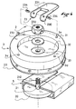
- FIG. 1 shows a snowboard 1 equipped with two position adjustment devices 2 according to the invention.
- Each device is intended to receive a fixation for the immobilization of a shoe (not shown).
- Different types of fasteners can adapt to such a device for retaining rigid shell shoes or soft type boots. It is therefore not in the spirit of present invention to be limited to the use of a particular type of fixation.
- each device comprises a plate central 3 connected to the board by a special mechanism which will described later.
- a base 4 whose main function is to support the shoe retaining means is shown in line dotted as an example.
- the base is secured to the plate and is oriented along a main axis O forming an angle of inclination ⁇ by relative to the longitudinal axis (I-I ').
- One of the objects of the invention is to ability to vary the angle of inclination ⁇ , at will, releasing the central plate 3 in rotation and providing a locking mechanism fast in the desired angular position.
- the snowboard also includes two portions of rails 5 arranged along the longitudinal axis (I-I ') and spaced from each other.
- the length of each rail portion and the spacing between them are parameters easily determined by a person skilled in the art to cover all, or at least most, of the usual settings used and wanted by users.
- Another object of the invention is therefore also to be able to vary the longitudinal position of the plate central 3 in relation to the board over the length of the rail portion planned, at the same time as the angular adjustment is obtained and without additional handling.
- each device it is preferable to provide for each device, a portion of rail distinct and separate so as to influence the free as little as possible bending of the board.
- each portion is not oriented strictly along the axis (I-I ') but on the contrary either slightly offset and parallel, or inclined with respect thereto.
- the adjusting device 2 comprises a central plate 3 in the form of a disc, provided with a surface lower 30 in contact with a friction means 22; himself in contact with the upper surface 10 of the board.
- An organ of slide 20 is housed inside the rail portion 5 and is connected to the central plate by a central rod 21 fixedly secured to the sliding member 20.
- the central plate 3 is provided with a upper receiving surface 31 intended to receive a base of fixing (not shown), a central housing 32; and inside the latter with a central bore 33 for the passage of the central rod 21.
- the central rod 21 is mounted free in vertical translation in the bore 33 of the plate.
- An actuating means 23 controls the central rod 21 in vertical translation.
- the central rod 21 includes a threaded portion 212 onto which is screwed a threaded adjusting means 232 such as a simple nut for example.
- a washer 233 is disposed between the means 232 and the board.
- the actuating means comprises a cam eccentric member 230 pivotally mounted on the adjusting means threaded 232 by two radial pins 234.
- the cam eccentric member is indirectly connected to the central rod by a pivot link and manually operable at by means of a lever 231 secured to the member to move the rod 21 in axial translation through the bore 33, upwards to reach the clamping position and vice versa, down to reach the position released.
- the threaded adjusting means 232 has the function of making it possible to adjust the clamping force in the clamping position of the plate.
- the central housing 32 has a sufficient depth relative to the surface 31 to contain the actuating means 23 without overshoot of lever 231 when the latter is in the retracted position corresponding to the clamping position of the plate.
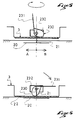
- the locked position of figure 6 is obtained by lowering the lever 231 in its retracted position. It drives in rotation the eccentric member 230 which bears on the central plate 3; this which moves the central rod 21 upwards and constrains the slide 20 to be reassembled in the rail portion.
- the organ eccentric exerts a tensile force on the rod and therefore on the slide, resting on the plate which compresses the means of friction 22 on the surface of the board.
- the tightening can be controlled by threaded adjusting means 232 before lowering the lift. By screwing, the cam is brought closer to the eccentric member of the surface of the plate along the central rod, and therefore the tightening is increased.
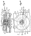
- Figures 7 and 8 illustrate a second embodiment of the invention. The only significant change from mode previous comes from the actuating means 23 which is different.
- a sliding member 20 is housed at inside the rail portion 5 and is connected to a central rod 21 of in solidarity.
- the central rod passes through the central bore 33 of the platinum. It is mounted freely in axial translation relative to the platinum by a sliding link. To allow transmission of vertical movement, the rod is blocked in rotation by a flat 211.
- the actuating means 23 has a lever 231 which controls in rotation of an annular ramp member 234 mounted by a pivot link sliding relative to the central rod 21 and which acts on one or more radial lugs 210 of the central rod to move the latter in axial translation upwards to reach the clamping position and, inversely downwards, to reach the released position.
- the central rod has two radially opposite lugs 210.
- the annular ramp member has, two ramp surfaces 234a for guiding the pins and which each have a gradual slope ending in position high by a radial recess 234b for blocking each lug in clamping position of the plate.
- the central plate 3 has a upper reception surface 31 and a central housing 32 of sufficient depth from the top surface to contain the member with an annular ramp without protruding either from it or from the end of the central rod relative to the upper surface of reception 31 when the upper blocking position is reached.
- the device comprises a second housing 34 formed under the plate, set back from the lower surface 30 of the plate in contact with the friction means, which communicates with the housing central 32 on the one hand and which opens out through an opening 34a on the side of the stage on the other hand.
- the lever meanwhile, has an arm 231a which connects the annular ramp member 234 through said housing and which extends out of the opening 34a by a lever 231b actuable in rotation.
- an elastic means such as one or more Belleville 24 washer (s), housed in the portion rail and which offers an elastic resistance to compression for keep the sliding member under pressure. More specifically, the 'Belleville' washer is simply mounted through the center rod and housed between the slide 20 and a support washer 25 whose width is chosen greater than the opening 50 of the rail.
- the clamping passage of the device in the released position is done simply by operating the lever 231b of the lever by about a quarter turn rotation.
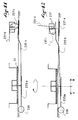
- Figures 9 and 10 detail another variant of the invention with an actuating lever offset relative to the plate; what has advantage of allowing adjustment without having to remove the shoe from retaining means directly or indirectly attached to the platinum.
- the device has an actuating means 23 which includes a transmission element 235 housed, at least in part, in the portion rail 5.
- the element is connected to the central rod 21 by a pivot link slippery. It has a first elongated portion 235a which ends by a support means 236 offset by a certain distance d1 with respect to the axis of the central rod.
- the support means 236 is in the form a cylindrical portion of width greater than the opening 40 of the rail.
- the actuating means has a second elongated portion 235b which extends on the opposite side to the first portion, and is connected by an offset clamping member 237, located at a distance d2 from the axis of the rod.
- the distance d1 of the first portion 235a is less than the distance d2 from the second portion 235b, so that the action of tightening of the offset clamping member 237 causes leverage which moves the central rod 21 in axial translation down to the clamping position of the plate.
- the transmission element 235 includes, between the two elongated portions 235a, 235b, a disc 235c support, through which the central rod passes.
- the 235c disc bears against the sliding member 20 to push it towards the bottom, by leverage generated during the clamping action of the offset clamping 237.
- Rod 237b is provided with a threaded portion on which is screwed a threaded adjusting means 237e.
- the eccentric member 237c is mounted swiveling directly on the threaded adjusting means by means of two radial pins 237f.
- the adjusting means 237e can be a hexagon nut for example. Its function is to allow the adjustment of the clamping force of the clamping means 237.
- the central rod 21 of the device is also provided with a portion threaded upper 212a. It is blocked in translation relative to the plate by an adjustable threaded element 212b, of the nut type for example. This element allows a backlash of the device.
- the threaded element takes place in a central housing 32 large enough to ability to handle it using a tool such as a key.
- Figure 11 shows the device in a configuration of locking.
- the lever 237d of the offset clamping member 237 is in retracted position; which has the effect of placing the cam of the organ eccentric 237c in support position on the end of the second elongated part 235b, which therefore moves downward and approximates the sliding member 237a which moves it towards the high by translational driving of the rod 237b.
- Support exercised down on the end of the second elongated portion is transmitted in an upward support of the support end 236 and in a more effort significant traction due to the leverage on the central rod which tends to bring the plate closer to the surface of the board and to compress the friction means 22.
- the lever In the unlocked position, the lever is in the high position; of so that the cam of the eccentric member 237c does not apply any more force tightening at the end of the second elongated portion 235b. Thereby, the downward traction force exerted on the slide disappears which frees the device in translation, and the plate which no longer exerts compression on the friction means is released, in turn, rotation.
- the entire device including the offset clamping member can be moved in translation in the rail portion in the direction wanted A or B.
- the friction means plays a role important since its function is to create between the lower surface of the plate and the upper surface of the board, an interface which when subjected to a compressive force, participates in immobilization of the rotating plate by friction effect.
- Such a means can consist of a disc of material chosen from those with compressibility and elasticity properties important. Among the materials likely to be suitable; we can particularly mention natural and artificial rubbers, some plastics, cork and felt. Of course, the disc constituting the friction means can be glued or screwed onto the surface bottom of the deck or on the top surface of the board so to facilitate the movement of the device in the rail portion.
- the plate has the shape of a disc provided at least four threaded holes 3a, 3b, 3c, 3d forming a quadrilateral for receiving a suitable mounting base ( Figures 3 and 4).
- the holes are separated two by two by a distance of 4 cm to meet the usual snowboard standard.
- the plate can take other forms than that of a disk.
- it can be an elongated plate of shape substantially identical to the sole of a shoe for reception direct from a snowboard binding of the 'hull' type or other.
- each rail portion is made up of a profiled element 6 having a substantially transverse profile rectangular.
- the profiled element also comprises lateral anchoring edges 67, 68 which extend the bottom wall and extend outwards, so to improve the strength of the anchor in the structure of the board.
Landscapes
- Clamps And Clips (AREA)
- Braking Arrangements (AREA)
- Footwear And Its Accessory, Manufacturing Method And Apparatuses (AREA)
- Sheet Holders (AREA)
- Pile Receivers (AREA)
- Binders And Loading Units For Sheaves (AREA)
- Portable Nailing Machines And Staplers (AREA)
Abstract
Description
Dispositif de réglage de la position d'une fixation sur une planche de glisse, en particulier de snowboard et planche de glisse adaptée à un tel dispositif.Device for adjusting the position of a binding on a plank gliding, in particular snowboard and gliding board adapted to such device.
La présente invention concerne un dispositif de réglage de la position d'une fixation sur une planche de glisse. Elle se rapporte plus particulièrement à un dispositif adapté pour une planche du type 'Snowboard'.The present invention relates to a position adjustment device of a fixation on a gliding board. It relates more particularly to a device suitable for a board of the type 'Snowboard'.
L'invention concerne aussi une planche de snowboard équipée selon le dispositif.The invention also relates to a snowboard equipped with device.
La pratique du snowboard se fait à l'aide d'une planche allongée, dont l'extrémité avant, au moins, est relevée pour former la spatule. Les deux chaussures de l'utilisateur sont immobilisées sur la planche par des éléments de retenue adaptés. Les positions adoptées pour la pratique de ce sport sont très variables en fonction des disciplines pratiquées, du niveau ou des habitudes de l'utilisateur, ou encore en fonction de sa morphologie Par exemple, pour la pratique de certaines disciplines orientées vers la recherche de la réalisation de figures, telle que le "free style" ou de la pratique "hors limite" telle que le "free ride", les pieds sont très écartés l'un de l'autre et sont très inclinés par rapport à l'axe longitudinal du snowboard dans une position sensiblement transversale, généralement non parallèles entre eux. Sur certaines planches totalement symétriques par rapport à l'axe transversal médian, les surfeurs adoptent une position de pieds dite en "canard" pour permettre la pratique indifféremment dans un sens ou dans un autre.Snowboarding is done using an elongated board, including the front end, at least, is raised to form the tip. The two user's shoes are immobilized on the board by suitable retaining elements. The positions adopted for the practice of this sport varies greatly depending on the discipline practiced, level or habits of the user, or depending on its morphology For example, for the practice of certain disciplines oriented towards the research of the realization of figures, such as "free style" or "out of bounds" practice such as "free ride ", the feet are very far apart and are very inclined by relation to the longitudinal axis of the snowboard in a position substantially transverse, generally not parallel to each other. Sure some boards completely symmetrical about the axis transverse median, the surfers adopt a position of feet called in "duck" to allow the practice indifferently in one direction or In another.
Au contraire, pour la pratique de disciplines de slalom ou de vitesse, les pieds sont moins écartés l'un de l'autre et se rapprochent, en inclinaison, de l'axe longitudinal médian.On the contrary, for the practice of slalom or speed disciplines, the feet are less spaced from each other and move closer together, inclination, of the median longitudinal axis.
Pour répondre à cette diversité de réglage, les systèmes actuels ne donnent pas entière satisfaction. L'un des plus répandu consiste à prévoir, sur le surf plusieurs rangées de trous filetés pour le passage de vis servant à immobiliser une platine généralement circulaire ; la platine maintenant elle-même une embase de fixation dans une position angulaire déterminée. Le brevet AT 1387/92 divulgue un système de réglage de ce type pour le support d'une fixation de snowboard. Selon ce dispositif, le choix des positions reste limité, notamment selon la direction longitudinale de la planche. De même, le réglage nécessite le recours à un outil tel qu'un tournevis et rend donc la manipulation longue et fastidieuse, et donc généralement impossible sur le terrain. Ces dispositifs ne sont pas non plus adaptés pour la location où la facilité et la rapidité du réglage sont prépondérantes.To respond to this diversity of adjustment, current systems do not not entirely satisfactory. One of the most common is provide several rows of threaded holes on the board for the passage of screws used to immobilize a generally circular plate; the plate itself holding a mounting base in a position angular determined. Patent AT 1387/92 discloses a system of adjustment of this type for the support of a snowboard binding. According to what device, the choice of positions remains limited, in particular according to the longitudinal direction of the board. Similarly, the adjustment requires the use a tool such as a screwdriver and therefore makes handling long and tedious, and therefore generally impossible in the field. These devices are not no longer suitable for rental where ease and speed of adjustment are paramount.
Le document DE-U-295 01 515 décrit un système de réglage de la position d'un dispositif de retenue d'une chaussure sur une planche. Le système de réglage fait coopérer des surfaces de contact ayant des creux et des bosses qui s'emboítent mutuellement les uns dans les autres pour s'opposer à des mouvements de rotation réciproques. Le système selon ce document permet un réglage pas à pas de la position, ce qui réduit le choix de possibilités de réglage.Document DE-U-295 01 515 describes a system for adjusting the position of a device for retaining a shoe on a board. The adjustment system brings together contact surfaces having recesses and bumps which interlock with each other in the others to oppose reciprocal rotational movements. The system according to this document allows step-by-step position adjustment, reducing the choice of setting.
Un des buts de la présente invention est donc de proposer un dispositif de réglage de la position d'une fixation qui apporte réellement un large choix de possibilité de réglage en particulier en orientation angulaire et en position longitudinale tout en restant facilement et rapidement manoeuvrable sans disposer d'outils particuliers.One of the aims of the present invention is therefore to propose a device for adjusting the position of a fixing which really brings a wide choice of adjustment possibilities in particularly in angular orientation and in longitudinal position while remaining easily and quickly maneuverable without having special tools.
Un autre but de l'invention est de proposer un dispositif qui s'adapte, en particulier en snowboard, à la plupart des systèmes actuels d'embase de fixation qui utilise le standard usuel 4x4 en servant ainsi d'interface de réglage entre le snowboard et l'embase.Another object of the invention is to propose a device which adapts, in particular in snowboard, to most current mounting base systems that use the usual standard 4x4 thus serving as an adjustment interface between the snowboard and the base.
La présente invention concerne aussi une planche de snowboard particulièrement adaptée pour recevoir le dispositif de réglage de position selon l'invention.The present invention also relates to a snowboard particularly adapted to receive the position adjustment device according to the invention.
Un des buts est donc aussi de proposer une planche de snowboard avec dispositif de réglage intégré qui s'adapte à la plupart des systèmes actuels d'embase de fixation utilisés. En plus, la planche offre une plage d'ajustement continu en position longitudinale permettant d'obtenir une adaptation aux différentes disciplines pratiquées en snowboard.One of the goals is therefore also to offer a snowboard with a integrated adjustment that adapts to most current mounting base systems used. In more, the board offers a range of continuous adjustment in longitudinal position allowing to obtain an adaptation to the different disciplines practiced in snowboarding.
Un autre but de l'invention est aussi de proposer une planche de snowboard qui possède une grande résistance à l'arrachement des fixations dans les conditions d'utilisation les plus dures.Another object of the invention is also to propose a snowboard which has a high resistance to tearing of the fasteners under the conditions of use the harder.
Pour répondre à ces objets ainsi qu'à d'autres, la présente invention se présente comme un dispositif de réglage de la position d'une fixation sur une planche de glisse destiné à coopérer dans une portion de rail ménagée dans la planche, caractérisé en ce qu'il comprend :
- une platine centrale reposant sur la planche pour recevoir directement, ou indirectement par l'intermédiaire d'une embase, un dispositif de retenue d'une chaussure ;
- un organe de coulissement logé à l'intérieur de la portion de rail et une tige centrale qui relie l'organe de coulissement à la platine ;
- un moyen de friction disposé entre la platine centrale et la surface de la planche ;
- un moyen d'actionnement qui commande la tige centrale en translation pour modifier la position verticale relative de l'organe de coulissement à l'intérieur de la portion de rail ; entre une position libérée de la platine en rotation et en translation le long de la portion de rail et une position de serrage au cours de laquelle la surface inférieure de la platine comprime le moyen de friction contre la face supérieure de la planche.
- a central plate resting on the board for receiving directly, or indirectly via a base, a device for retaining a shoe;
- a sliding member housed inside the rail portion and a central rod which connects the sliding member to the plate;
- friction means arranged between the central plate and the surface of the board;
- an actuating means which controls the central rod in translation to modify the relative vertical position of the sliding member inside the rail portion; between a position freed from the plate in rotation and in translation along the rail portion and a clamping position during which the lower surface of the plate compresses the friction means against the upper face of the board.
Différents modes de réalisation illustrent l'invention qui sera mieux comprise en se référant à la description détaillée suivante, ainsi qu'aux dessins qui s'y rattachent dont :
- la figure 1 est une vue générale en élévation d'une planche de snowboard avec dispositif de réglage intégré selon l'invention ;
- la figure 2 est une vue en coupe longitudinale selon A-A du dispositif de la figure 1 selon un premier mode de réalisation ;
- la figure 3 est une vue en élévation détaillée du dispositif de la figure 2;
- la figure 4 est une vue en perspective éclatée du dispositif des figures 2 et 3 ;
- la figure 5 est une vue schématique du principe de fonctionnement du dispositif des figures 2 à 4 avant serrage ;
- la figure 6 est une vue schématique similaire à celle de la figure 5 après serrage ;
- la figure 7 est une vue en coupe A-A selon une variante de l'invention ;
- la figure 8 est une vue en élévation détaillée de la variante de la figure 7 ;
- la figure 9 est une vue en coupe A-A d'une seconde variante de l'invention ;
- la figure 10 est une vue de dessus de la variante de la figure 9 ;
- la figure 11 est une vue schématique du principe de fonctionnement de la variante des figures 9 et 10 avant serrage ;
- la figure 12 est une vue schématique similaire à celle de la figure 11 après serrage ;
- la figure 13 est une vue en coupe transversale de la planche de la figure 1 selon la ligne B-B.
- Figure 1 is a general elevational view of a snowboard with integrated adjustment device according to the invention;
- Figure 2 is a longitudinal sectional view along AA of the device of Figure 1 according to a first embodiment;
- Figure 3 is a detailed elevational view of the device of Figure 2;
- Figure 4 is an exploded perspective view of the device of Figures 2 and 3;
- Figure 5 is a schematic view of the operating principle of the device of Figures 2 to 4 before tightening;
- Figure 6 is a schematic view similar to that of Figure 5 after tightening;
- Figure 7 is a sectional view AA according to a variant of the invention;
- Figure 8 is a detailed elevational view of the variant of Figure 7;
- Figure 9 is a sectional view AA of a second variant of the invention;
- Figure 10 is a top view of the variant of Figure 9;
- Figure 11 is a schematic view of the operating principle of the variant of Figures 9 and 10 before tightening;
- Figure 12 is a schematic view similar to that of Figure 11 after tightening;
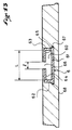
- Figure 13 is a cross-sectional view of the board of Figure 1 along line BB.
La figure 1 montre une planche de snowboard 1 équipée de deux
dispositifs de réglage de position 2 selon l'invention. Chaque dispositif
est destiné à recevoir une fixation pour l'immobilisation d'une
chaussure (non représentée). Différents types de fixations peuvent
s'adapter à un tel dispositif pour retenir des chaussures à coque rigide
ou des bottes du type souple. Il n'est donc pas dans l'esprit de la
présente invention de se limiter à l'usage d'un type particulier de
fixation. Figure 1 shows a
Dans le mode représenté, chaque dispositif comprend une platine
centrale 3 reliée à la planche par un mécanisme particulier qui sera
décrit plus loin. Une embase 4 dont la fonction principale est de
supporter le moyen de retenue de la chaussure est représentée en trait
pointillé à titre d'exemple. L'embase est solidaire de la platine et
s'oriente selon un axe principal O formant un angle d'inclinaison α par
rapport à l'axe longitudinal (I-I'). L'un des objets de l'invention est de
pouvoir faire varier l'angle d'inclinaison α, à volonté, en libérant la
platine centrale 3 en rotation et en prévoyant un mécanisme de blocage
rapide dans la position angulaire désirée.In the mode shown, each device comprises a plate
central 3 connected to the board by a special mechanism which will
described later. A
La planche de snowboard comprend aussi deux portions de rails 5
disposés selon l'axe longitudinal (I-I') et espacées l'une de l'autre. La
longueur de chaque portion de rail et l'espacement entre eux sont des
paramètres facilement déterminables par l'homme de l'art pour couvrir
l'ensemble, ou tout au moins la plupart, des réglages usuels utilisés et
recherchés par les utilisateurs. Un autre objet de l'invention est donc
aussi de pouvoir faire varier la position longitudinale de la platine
centrale 3 par rapport à la planche sur la longueur de portion de rail
prévue, en même temps que le réglage angulaire est obtenu et sans
manipulation supplémentaire.The snowboard also includes two portions of
Il est préférable de prévoir pour chaque dispositif, une portion de rail distincte et séparée de façon à influencer le moins possible la libre flexion de la planche. En revanche, on peut envisager que chaque portion ne soit pas orientée strictement selon l'axe (I-I') mais au contraire soit légèrement décalée et parallèle, ou inclinée par rapport à celui-ci.It is preferable to provide for each device, a portion of rail distinct and separate so as to influence the free as little as possible bending of the board. However, we can consider that each portion is not oriented strictly along the axis (I-I ') but on the contrary either slightly offset and parallel, or inclined with respect thereto.
Selon le premier mode des figures 2 à 4, le dispositif de réglage 2
comprend une platine centrale 3 en forme de disque, munie d'une surface
inférieure 30 en contact avec un moyen de friction 22 ; lui-même en
contact avec la surface supérieure 10 de la planche. Un organe de
coulissement 20 est logé à l'intérieur de la portion de rail 5 et est relié
à la platine centrale par une tige centrale 21 solidaire fixement de
l'organe de coulissement 20. La platine centrale 3 est munie d'une
surface supérieure de réception 31 destinée à recevoir une embase de
fixation (non représentée), d'un logement central 32 ; et à l'intérieur de
celui-ci d'un alésage central 33 pour le passage de la tige centrale 21.
La tige centrale 21 est montée libre en translation verticale dans
l'alésage 33 de la platine.According to the first mode of Figures 2 to 4, the adjusting
Un moyen d'actionnement 23 commande la tige centrale 21 en
translation verticale. La tige centrale 21 comprend une portion filetée
212 sur laquelle est vissé un moyen de réglage fileté 232 tel qu'un
simple écrou par exemple. Une rondelle 233 est disposée entre le moyen
de réglage 232 et la platine. Le moyen d'actionnement comprend un
organe d'excentrique à came 230 monté pivotant sur le moyen de réglage
fileté 232 par deux goupilles radiales 234.An actuating means 23 controls the
Dans ce mode, l'organe excentrique à came est relié indirectement à
la tige centrale par une liaison pivot et actionnable manuellement au
moyen d'un levier 231 solidaire de l'organe pour déplacer la tige 21 en
translation axiale à travers l'alésage 33, vers le haut pour atteindre la
position de serrage et inversement, vers le bas pour atteindre la
position libérée.In this mode, the cam eccentric member is indirectly connected to
the central rod by a pivot link and manually operable at
by means of a
Le moyen de réglage fileté 232 a pour fonction de permettre d'ajuster l'effort de serrage dans la position de serrage de la platine.The threaded adjusting means 232 has the function of making it possible to adjust the clamping force in the clamping position of the plate.
Le logement central 32 a une profondeur suffisante par rapport à la
surface 31 pour contenir le moyen d'actionnement 23 sans dépassement
du levier 231 lorsque celui-ci se trouve en position escamotée
correspondant à la position de serrage de la platine.The
Le fonctionnement du dispositif est le suivant : en position
déverrouillée, représentée à la figure 5, le levier 231 est relevé, de
sorte que l'organe d'excentrique à came qui lui est solidaire, se trouve
dégagé de la surface de la platine centrale 3. La platine étant montée
par une liaison pivot glissant sur la tige 21 peut alors être orientée
dans la position angulaire désirée. De même, sans effort de serrage,
l'organe de coulissement, ou coulisseau 20, est libéré en translation
dans la portion de rail, permettant aussi de déplacer l'ensemble du
dispositif dans le sens choisi A ou B.The operation of the device is as follows: in position
unlocked, shown in Figure 5, the
La position verrouillée de la figure 6 est obtenue en abaissant le
levier 231 dans sa position escamotée. Celui-ci entraíne en rotation
l'organe d'excentrique 230 qui prend appui sur la platine centrale 3 ; ce
qui déplace la tige centrale 21 vers le haut et contraint le coulisseau
20 à remonter dans la portion de rail. En position de serrage, l'organe
d'excentrique exerce un effort de traction sur la tige et donc sur le
coulisseau, en s'appuyant sur la platine qui comprime le moyen de
friction 22 sur la surface de la planche. Dans cette configuration, le
déplacement longitudinal du coulisseau dans le rail et le déplacement
angulaire de la platine ne sont plus permis. Le serrage peut être
contrôlé par le moyen de réglage fileté 232 avant d'abaisser le lever.
En vissant, on rapproche la came de l'organe d'excentrique de la surface
de la platine le long de la tige centrale, et on augmente donc le serrage. The locked position of figure 6 is obtained by lowering the
Les figures 7 et 8 illustrent un second mode de réalisation de l'invention. Le seul changement important par rapport au mode précédent provient du moyen d'actionnement 23 qui est différent.Figures 7 and 8 illustrate a second embodiment of the invention. The only significant change from mode previous comes from the actuating means 23 which is different.
On retrouve une platine centrale 3 en forme de disque en contact avec
un moyen de friction 22. Un organe de coulissement 20 est logé à
l'intérieur de la portion de rail 5 et est relié à une tige centrale 21 de
manière solidaire. La tige centrale traverse l'alésage central 33 de la
platine. Elle est montée libre en translation axiale par rapport à la
platine par une liaison glissière. Pour permettre une transmission du
mouvement vertical, la tige est bloquée en rotation par un méplat 211.There is a
Le moyen d'actionnement 23 présente un levier 231 qui commande en
rotation un organe à rampe annulaire 234 monté par une liaison pivot
glissant par rapport à la tige centrale 21 et qui agit sur un ou plusieurs
ergots radiaux 210 de la tige centrale pour déplacer celle-ci en
translation axiale vers le haut pour atteindre la position de serrage et,
inversement vers le bas, pour atteindre la position libérée.The actuating means 23 has a
Comme le montre la figure 8, la tige centrale est munie de deux ergots 210 radialement opposés. L'organe à rampe annulaire présente, quant à lui, deux surfaces de rampe 234a pour le guidage des ergots et qui présentent chacune une pente progressive se terminant en position haute par un creux radial 234b pour le blocage de chaque ergot en position de serrage de la platine.As shown in Figure 8, the central rod has two radially opposite lugs 210. The annular ramp member has, two ramp surfaces 234a for guiding the pins and which each have a gradual slope ending in position high by a radial recess 234b for blocking each lug in clamping position of the plate.
Comme dans le mode précédent, la platine centrale 3 présente une
surface supérieure de réception 31 et un logement central 32 de
profondeur suffisante par rapport à la surface supérieure, pour contenir
l'organe à rampe annulaire sans dépassement, ni de celui-ci, ni de
l'extrémité de la tige centrale par rapport à la surface supérieure de
réception 31 lorsque la position haute de blocage est atteinte.As in the previous mode, the
Le dispositif comprend un second logement 34 ménagé sous la
platine, en retrait par rapport à la surface inférieure 30 de la platine en
contact avec le moyen de friction, qui communique avec le logement
central 32 d'une part et qui est débouchant par une ouverture 34a sur le
côté de la platine d'autre part. Le levier, quant à lui, est muni d'un bras
231a qui relie l'organe à rampe annulaire 234 à travers ledit logement
et qui se prolonge hors de l'ouverture 34a par une manette 231b
actionnable en rotation.The device comprises a
Le dispositif n'étant pas réglable, on prévoit un moyen élastique,
telle qu'une ou plusieurs rondelle(s) Belleville 24, logé dans la portion
de rail et qui oppose une résistance élastique à la compression pour
maintenir l'organe de coulissement en pression. Plus précisément, la
rondelle 'Belleville' est simplement montée à travers la tige centrale et
logée entre le coulisseau 20 et une rondelle d'appui 25 dont la largeur
est choisie supérieure à l'ouverture 50 du rail.The device not being adjustable, an elastic means is provided,
such as one or
Le passage de serrage du dispositif à la position libérée, et
inversement, se fait simplement en actionnant la manette 231b du
levier par une rotation d'un quart de tour environ.The clamping passage of the device in the released position, and
conversely, is done simply by operating the
Les figures 9 et 10 détaillent une autre variante de l'invention avec un levier d'actionnement décalé par rapport à la platine ; ce qui a pour avantage de permettre un réglage sans devoir dégager la chaussure des moyens de retenue solidaires directement ou indirectement de la platine.Figures 9 and 10 detail another variant of the invention with an actuating lever offset relative to the plate; what has advantage of allowing adjustment without having to remove the shoe from retaining means directly or indirectly attached to the platinum.
Le dispositif possède un moyen d'actionnement 23 qui comprend un
élément de transmission 235 logé, en partie au moins, dans la portion
de rail 5. L'élément est relié à la tige centrale 21 par une liaison pivot
glissante. Il présente une première portion allongée 235a qui se termine
par un moyen d'appui 236 décalé d'une certaine distance d1 par rapport à
l'axe de la tige centrale. Le moyen d'appui 236 se présente sous la forme
d'une partie cylindrique de largeur supérieure à l'ouverture 40 du rail.
Le moyen d'actionnement présente une seconde portion allongée 235b
qui se prolonge du côté opposé à la première portion, et est reliée par
un organe de serrage décalé 237, situé à une distance d2 de l'axe de la
tige. La distance d1 de la première portion 235a est inférieure à la
distance d2 de la seconde portion 235b, de telle sorte que l'action de
serrage de l'organe de serrage décalé 237 provoque un effet de levier
qui déplace la tige centrale 21 en translation axiale vers le bas jusqu'à
la position de serrage de la platine.The device has an actuating means 23 which includes a
Pour améliorer l'effet de levier engendré, l'élément de transmission
235 comprend, entre les deux portions allongées 235a, 235b, un disque
d'appui 235c, au travers duquel passe la tige centrale. Le disque 235c
prend appui contre l'organe de coulissement 20 pour le repousser vers le
bas, par effet de levier engendré lors de l'action de serrage du moyen de
serrage décalé 237.To improve the leverage generated, the
Le moyen de serrage décalé 237 comprend :
- un second organe de coulissement ou coulisseau 237a logé à l'intérieur de la portion de rail ;
- une tige 237b fixée à l'organe de coulissement 237a et se prolongeant en dehors du rail et au travers de la seconde portion allongée 235b, de façon libre en translation ;
- un organe d'excentrique à came 237c relié à la tige par une liaison pivot et actionnable au moyen d'un levier 237d solidaire dudit organe pour déplacer la tige en translation axiale vers le haut pour atteindre la position de serrage, et inversement, vers le bas pour atteindre la position libérée.
- a second sliding member or
slide 237a housed inside the rail portion; - a rod 237b fixed to the sliding
member 237a and extending outside the rail and through the second elongated portion 235b, so as to be free in translation; - a cam
eccentric member 237c connected to the rod by a pivot link and actuable by means of alever 237d secured to said member to move the rod in axial translation upward to reach the clamping position, and conversely, towards the down to reach the released position.
La tige 237b est munie d'une portion filetée sur laquelle est vissée
un moyen de réglage fileté 237e. L'organe d'excentrique 237c est monté
pivotant directement sur le moyen de réglage fileté au moyen de deux
goupilles radiales 237f.Rod 237b is provided with a threaded portion on which is screwed
a threaded adjusting means 237e. The
Le moyen de réglage 237e peut être un écrou à six pans par exemple. Il a pour fonction de permettre l'ajustement de l'effort de serrage du moyen de serrage 237.The adjusting means 237e can be a hexagon nut for example. Its function is to allow the adjustment of the clamping force of the clamping means 237.
La tige centrale 21 du dispositif est munie aussi d'une portion
supérieure filetée 212a. Elle est bloquée en translation par rapport à la
platine par un élément fileté réglable 212b, du type écrou par exemple.
Cet élément permet un rattrapage de jeu du dispositif. L'élément fileté
prend place dans un logement central 32 suffisamment large pour
pouvoir le manipuler au moyen d'un outil tel qu'une clef.The
Le principe de fonctionnement est illustré par les figures schématiques 11 et 12.The operating principle is illustrated by the figures schematics 11 and 12.
La figure 11 montre le dispositif dans une configuration de
verrouillage. Le lever 237d de l'organe de serrage décalé 237 est en
position escamotée ; ce qui a pour effet de placer la came de l'organe
d'excentrique 237c en position d'appui sur l'extrémité de la seconde
partie allongée 235b, qui de ce fait se déplace vers le bas et se
rapproche de l'organe de coulissement 237a qui se déplace lui vers le
haut par entraínement en translation de la tige 237b. L'appui exercé
vers le bas sur l'extrémité de la seconde portion allongée se transmet
en un appui vers le haut de l'extrémité d'appui 236 et en un effort plus
important de traction du à l'effet de levier sur la tige centrale qui tend
à rapprocher la platine de la surface de la planche et à comprimer le
moyen de friction 22.Figure 11 shows the device in a configuration of
locking. The
En position de déverrouillage, le levier est en position haute ; de
sorte que la came de l'organe d'excentrique 237c n'applique plus d'effort
de serrage à l'extrémité de la seconde portion allongée 235b. De ce fait,
l'effort en traction vers le bas exercé sur le coulisseau disparaít ce qui
libère le dispositif en translation, et la platine qui n'exerce plus de
compression sur le moyen de friction est libérée, quant à elle, en
rotation. L'ensemble du dispositif y compris l'organe de serrage décalé
peut être déplacé en translation dans la portion de rail dans la direction
voulue A ou B.In the unlocked position, the lever is in the high position; of
so that the cam of the
Dans tous les modes représentés, le moyen de friction joue un rôle important puisqu'il a pour fonction de créer entre la surface inférieure de la platine et la surface supérieure de la planche, une interface qui lorsqu'elle est soumise à un effort de compression, participe à l'immobilisation de la platine en rotation par effet de friction.In all the modes represented, the friction means plays a role important since its function is to create between the lower surface of the plate and the upper surface of the board, an interface which when subjected to a compressive force, participates in immobilization of the rotating plate by friction effect.
Un tel moyen peut être constitué d'un disque en matériau choisi parmi ceux possédant des propriétés de compressibilité et d'élasticité importantes. Parmi les matériaux susceptibles de convenir ; on peut citer tout particulièrement les caoutchoucs naturels et artificiels, certains plastiques, le liège et le feutre. Bien entendu, le disque constituant le moyen de friction peut être collé ou vissé sur la surface inférieure de la platine ou sur la surface supérieure de la planche afin de faciliter le déplacement du dispositif dans la portion de rail.Such a means can consist of a disc of material chosen from those with compressibility and elasticity properties important. Among the materials likely to be suitable; we can particularly mention natural and artificial rubbers, some plastics, cork and felt. Of course, the disc constituting the friction means can be glued or screwed onto the surface bottom of the deck or on the top surface of the board so to facilitate the movement of the device in the rail portion.
Dans les exemples illustrés, la platine a la forme d'un disque muni
d'au moins quatre trous filetés 3a, 3b, 3c, 3d formant un quadrilatère
pour la réception d'une embase de fixation adaptée (figure 3 et 4).In the examples illustrated, the plate has the shape of a disc provided
at least four threaded
De préférence, les trous sont séparés deux à deux d'une distance de 4 cm pour répondre au standard usuel du snowboard.Preferably, the holes are separated two by two by a distance of 4 cm to meet the usual snowboard standard.
Bien entendu, la platine peut prendre d'autres formes que celle d'un disque. Par exemple, il peut s'agir d'une plaque allongée de forme sensiblement identique à la semelle d'une chaussure pour la réception directe d'une fixation de snowboard du type 'coque' ou autre.Of course, the plate can take other forms than that of a disk. For example, it can be an elongated plate of shape substantially identical to the sole of a shoe for reception direct from a snowboard binding of the 'hull' type or other.
Comme le montre la figure 13, chaque portion de rail est constituée
d'un élément profilé 6 ayant un profil transversal sensiblement
rectangulaire.As shown in Figure 13, each rail portion is made up
of a profiled
Il comprend un canal 60 délimité par une paroi de fond 61, deux
parois latérales 62, 63 reliées à la paroi de fond et deux bords
supérieurs 64, 65 qui s'opposent pour former une ouverture 66 de
largeur l inférieure à la plus grande largeur L du canal. Au lieu d'une
forme rectangulaire, le profil peut être choisi trapézoïdal, par exemple.
L'élément profilé comprend aussi des bords latéraux d'ancrage 67, 68
qui prolongent la paroi de fond et s'étendent vers l'extérieur, afin
d'améliorer la résistance de l'ancrage dans la structure de la planche.It includes a channel 60 delimited by a bottom wall 61, two
Bien entendu, la présente invention n'est pas limitée aux modes de réalisation qui ont été explicitement décrits, mais elle en inclut les diverses variantes et généralisation contenues dans le domaine des revendications ci-après.Of course, the present invention is not limited to the modes of which have been explicitly described, but it includes the various variants and generalizations contained in the field of claims below.
Claims (19)
- Device for adjusting the position of a binding on a gliding board adapted to cooperate with a rail portion (5) provided in the board, comprising:a central plate (3) resting on the board to receive a boot retaining device, directly, or indirectly through a base;a sliding member (20) housed within the rail portion (5) and a central stud (21) which connects the sliding member (20) to the plate (3);an actuation means (23) which controls the central stud (21) in translation in order to modify the relative vertical position of the sliding member (20) within the rail portion (5); between a released position of the plate in rotation and in translation along the rail portion and a tightening position,
characterized in that a compressible friction means (22) is arranged between the central plate (3) and the upper surface (10) of the board to ensure, by friction resulting from its compression against said upper surface (10), the immobilization of the plate in rotation and in translation along the rail portion in the tightening position of the central plate (3). - Adjusting device according to claim 1, characterized in that the actuation means (23) has an eccentric cam member (230) connected to the central stud (21) by a pivot linkage and manually actuated by means of a lever (231) affixed to said member to displace the stud (21) upwardly in axial translation to reach the tightening position, and inversely downwardly to reach the released position.
- Adjusting device according to claim 2, characterized in that the actuation means comprises a threaded adjusting means (232) on which the eccentric cam member (230) is pivotally mounted; the threaded adjusting means (232) being screwed into an adjustable position on a complementary threaded portion (212) of the central stud (21) to allow adjusting the tightening force in the tightening position of the plate (3).
- Adjusting device according to claim 2 or 3, characterized in that the central plate (3) has an upper receiving surface (31) and a central housing (32) having sufficient depth with respect to said surface (31) to hold the action means (23) without extending past the lever (231) when the latter is in the retracted position corresponding to the tightening position of the plate.
- Adjusting device according to claim 1, characterized in that the actuation means (23) has a lever (231) which controls in rotation an annular ramp member (234) mounted by a sliding pivot linkage with respect to the central stud (21) and which acts on one or more radial lugs (210) of the central stud (21) to displace the latter upwardly in axial translation to reach the tightening position, and inversely downwardly to reach the released position.
- Adjusting device according to claim 5, characterized in that the central stud (21) is equipped with two radially opposed logs (210), and in that the annular ramp member (234) has two ramp surfaces (234a) each having a progressive slant ending in a raised position by a radial hollow (234b) for blocking each lug in the tightening position of the plate.
- Device according to claim 6, characterized in that the central plate (3) has an upper receiving surface (31) and a central housing (32) having a sufficient depth with respect to said surface, in order to hold the annular ramp member (234) without extending past the latter or the end of the central stud (21) with respect to the upper receiving surface (31) when the raised blocking position is reached.
- Adjusting device according to claim 5, 6, or 7, characterized in that a second housing (34) is provided under the plate, set back with respect to the lower surface (30) of the plate in contact with the friction means (22), which communicates with the central housing (32), on the one had, and which opens out with an opening on the side of the plate, on the other hand; the lever (231) of the actuation means (23) being equipped with one arm (231a) connecting the annular ramp member (234) through said housing (32) and extending beyond the opening (34a) by a handle (231b) which can be actuated in rotation.
- Adjusting device according to any of claims 5-8, characterized in that an elastic means (24) is housed in the rail portion (5) which opposes an elastic resistance to the compression in order to maintain the sliding member (21) under pressure.
- Adjusting device according to claim 1, characterized in that the actuation means (23) comprises a transmission element (235) housed, at least in part, in the rail portion (5) connected to the central stud (21) by a sliding pivot linkage, having a first elongated portion (235a) which ends by a support means (236) offset by a certain distance d1 with respect to the axis of the central stud; a second elongated portion (235b) extending on the side opposite to the first portion and connected by an offset tightening member (237) located at a distance d2 from the axis of the stud (21), with d1<d2, such that the tightening action causes a lever effect that displaces the stud in a downward axial translation until the tightening position of the plate.
- Adjusting device according to claim 10, characterized in that the transmission element (235) comprises, between the two elongated portions (235a, 235b), a support disk (235c) through which the central stud (21) passes; said disk taking support against the sliding member (20) to push it downwardly, by the lever effect generated during the tightening action of the offset tightening means (237).
- Adjusting device according to claim 10 or 11, characterized in that the offset tightening means (237) comprises:a second sliding member (237a) housed within the rail portion (5);a stud (237b) attached to the sliding member (237a) and extending outside of the rail and through the second elongated portion (235b), freely in translation;an eccentric cam member (237c) directly or indirectly connected to the stud (237b) by a pivot linkage and manually actuated by means of a lever (237d) affixed to said member in order to displace the stud (21) upwardly in axial translation to reach the tightening position, and inversely downwardly to reach the released position.
- Adjusting device according to claim 12, characterized in that the offset tightening means (237) comprises a threaded adjusting means (237e) on which the eccentric cam member (237c) is pivotally mounted; the threaded adjusting means (237e) being screwed in an adjustable position on a threaded portion of the stud (237b) to allow adjusting the tightening force of the tightening means.
- Adjusting device according to any of claims 10-13, characterized in that the central stud (21) is quipped with a threaded upper portion (212a), blocked in translation with respect to the central plate by an adjustable threaded element (212b) to allow backlash elimination for the device.
- Adjusting device according to any of the preceding claims, characterized in that the friction means (22) is constituted of an element made of a deformable and elastic material selected from the natural and artificial rubbers, certain plastics, cork and felt.
- Adjusting device according to any of the preceding claims, characterized in that the central plate (3) has the shape of a disk equipped with at least four threaded holes forming a quadrangle for receiving an adapted binding base.
- Snowboard equipped with an adjusting device according to any of claims 1-16, characterized in that it comprises two rail portions (5) arranged substantially along the longitudinal axis (I-I') and spaced apart.
- Snowboard according to claim 17, characterized in that each rail portion (5) is constituted of a shaped element (6) having a substantially rectangular or trapezoidal section which comprises a channel (60) demarcated by a bottom wall (61), two lateral walls (62, 63) connected to the bottom wall (61) and two upper edges (64, 65) inwardly opposing one another to form an opening (66) having a width (l) lesser than the greatest width (L) of the channel (60).
- Snowboard according to claim 18, characterized in that the shaped element (6) comprises lateral anchoring edges (67, 68) which extend the bottom wall (61) and extend outwardly.
Applications Claiming Priority (3)
| Application Number | Priority Date | Filing Date | Title |
|---|---|---|---|
| FR9509055A FR2736842B1 (en) | 1995-07-21 | 1995-07-21 | SNOWBOARD SUITABLE FOR SNOW SURFING PRACTICE. |
| FR9509055 | 1995-07-21 | ||
| PCT/FR1996/000926 WO1997003733A1 (en) | 1995-07-21 | 1996-06-17 | Device for adjusting the position of a binding on a snowboard |
Publications (2)
| Publication Number | Publication Date |
|---|---|
| EP0840640A1 EP0840640A1 (en) | 1998-05-13 |
| EP0840640B1 true EP0840640B1 (en) | 1999-03-24 |
Family
ID=9481381
Family Applications (1)
| Application Number | Title | Priority Date | Filing Date |
|---|---|---|---|
| EP96922934A Expired - Lifetime EP0840640B1 (en) | 1995-07-21 | 1996-06-17 | Device for adjusting the position of a binding on a snowboard |
Country Status (6)
| Country | Link |
|---|---|
| EP (1) | EP0840640B1 (en) |
| JP (1) | JPH11509440A (en) |
| AT (1) | ATE177966T1 (en) |
| DE (1) | DE69601878D1 (en) |
| FR (1) | FR2736842B1 (en) |
| WO (1) | WO1997003733A1 (en) |
Cited By (2)
| Publication number | Priority date | Publication date | Assignee | Title |
|---|---|---|---|---|
| DE10343887B3 (en) * | 2003-09-19 | 2004-12-09 | Goodwell International Ltd., Tortola | Snowboarding binding for a snowboard comprises a base plate, a pin plate, a base plate, a retaining plate, and a clamping plate |
| US7063346B2 (en) | 2003-03-25 | 2006-06-20 | Goodwell International Ltd. | Snowboard binding |
Families Citing this family (26)
| Publication number | Priority date | Publication date | Assignee | Title |
|---|---|---|---|---|
| US6786502B2 (en) * | 1997-07-28 | 2004-09-07 | Stephen R. Carlson | Longitudinally adjustable mount for a snowboard binding |
| US6283482B1 (en) * | 1998-12-07 | 2001-09-04 | The Burton Corporation | Binding with a tool-free selectively adjustable leg support member |
| FR2791268B1 (en) * | 1999-03-25 | 2001-04-27 | Rossignol Sa | SNOW SURF PROVIDED WITH LONGITUDINAL GROOVES FOR RECEIVING BINDING MECHANISMS |
| DE19924240A1 (en) * | 1999-05-27 | 2000-11-30 | Head Sport Ag | Snowboard |
| DE19924229A1 (en) * | 1999-05-27 | 2000-11-30 | Head Sport Ag | Snowboard |
| US6364323B1 (en) | 1999-12-07 | 2002-04-02 | The Burton Corporation | Tool-free adjustment system for a leg support member of a binding |
| FR2802109B1 (en) | 1999-12-13 | 2002-01-25 | Emery Sa | CONNECTION DEVICE BETWEEN A SHOE FIXATION AND A SLIDING BOARD |
| DE50005017D1 (en) * | 2000-02-04 | 2004-02-19 | Tyrolia Technology Gmbh Schwec | Adjustment device for a snowboard binding and a snowboard binding |
| US20020111094A1 (en) * | 2000-09-14 | 2002-08-15 | Jensen Kenneth Val | Water sports boot binding camlock screw |
| IT1316560B1 (en) * | 2000-12-28 | 2003-04-22 | Benetton Spa | ANGULAR ADJUSTMENT DEVICE, PARTICULARLY FOR A DASNOWBOARD ATTACK. |
| ITTV20010008U1 (en) * | 2001-01-30 | 2002-07-30 | Benetton Spa | SAFETY DEVICE PARTICULARLY FOR SKI BINDINGS |
| GB0105318D0 (en) * | 2001-03-05 | 2001-04-18 | Williams Christopher I | Snowboard binding attachment system |
| FR2832319B1 (en) * | 2001-11-21 | 2004-10-22 | Salomon Sa | SNOW SNOWBOARD, AND ASSEMBLY COMPRISING THE SNOWBOARD AND TWO DEVICES FOR RETAINING A SHOE ON THE BOARD |
| FR2834909B1 (en) | 2002-01-18 | 2004-04-09 | Emery Sa | IMPROVEMENT FOR A DEVICE FOR RETAINING A SHOE ON A SNOWBOARD OF THE SURF TYPE |
| US7300070B2 (en) | 2004-05-10 | 2007-11-27 | Jean-Francois Pelchat | Binding mounting system for recreational board |
| WO2007034080A1 (en) * | 2005-09-22 | 2007-03-29 | Gilibert Rene-Pierre | Device for retaining a shoe on a gliding board |
| FR2894836B1 (en) | 2005-12-16 | 2008-02-22 | Salomon Sa | BACKGROUND SKI SET AND DOWNHOLE SKI FIXING DEVICE |
| FR2899121B1 (en) * | 2006-03-29 | 2008-07-04 | Salomon Sa | BACKGROUND SKI SET AND DOWNHOLE SKI FIXING DEVICE |
| DE602007003983D1 (en) * | 2006-07-07 | 2010-02-04 | Burton Corp | GLIDEBOARD BINDING |
| FR2908666B1 (en) * | 2006-11-17 | 2009-03-06 | Salomon Sa | DEVICE FOR HOSTING A FOOT OR SHOE ON A SPORT MACHINE |
| FR2912317B1 (en) | 2007-02-13 | 2009-05-08 | Salomon Sa | ASSEMBLY COMPRISING A DEVICE FOR THE SOLIDARIZATION OF A PLATINUM. |
| US8128117B2 (en) | 2007-06-14 | 2012-03-06 | Flow Sports, Inc. | Tool-free adjustable binding for sports board |
| US9016714B2 (en) | 2009-04-30 | 2015-04-28 | Jf Pelchat Inc. | Binding system for recreational board |
| WO2010124382A1 (en) | 2009-04-30 | 2010-11-04 | Pelchat Jean-Francois | Binding system for recreational board |
| FR3010323B1 (en) * | 2013-09-06 | 2017-07-21 | Rossignol Sa | SLIDING BOARD AND METHOD FOR MANUFACTURING THE SAME |
| RU199640U1 (en) * | 2020-03-23 | 2020-09-11 | Роман Владимирович Шамов | Ski Bindings Body Installer |
Family Cites Families (4)
| Publication number | Priority date | Publication date | Assignee | Title |
|---|---|---|---|---|
| FR2575660A1 (en) * | 1985-01-09 | 1986-07-11 | Bunand Fabrice | SNOWBOARD OR "SURF" WITH AN ADJUSTABLE FRONT CALIPER AND DESOLIDARIZABLE MINI-SKI |
| EP0365611A1 (en) * | 1988-03-17 | 1990-05-02 | Aitec Ag | Snow glider |
| EP0351298A3 (en) * | 1988-07-14 | 1990-08-22 | Societe Emery | Binding for a monoski |
| CH688540A5 (en) * | 1994-02-04 | 1997-11-14 | Urs P Meyer | Fastening device for bonds on snowboards and skis. |
-
1995
- 1995-07-21 FR FR9509055A patent/FR2736842B1/en not_active Expired - Fee Related
-
1996
- 1996-06-17 AT AT96922934T patent/ATE177966T1/en not_active IP Right Cessation
- 1996-06-17 WO PCT/FR1996/000926 patent/WO1997003733A1/en active IP Right Grant
- 1996-06-17 DE DE69601878T patent/DE69601878D1/en not_active Expired - Lifetime
- 1996-06-17 JP JP9506341A patent/JPH11509440A/en not_active Ceased
- 1996-06-17 EP EP96922934A patent/EP0840640B1/en not_active Expired - Lifetime
Cited By (5)
| Publication number | Priority date | Publication date | Assignee | Title |
|---|---|---|---|---|
| US7063346B2 (en) | 2003-03-25 | 2006-06-20 | Goodwell International Ltd. | Snowboard binding |
| DE10313342B4 (en) * | 2003-03-25 | 2007-06-28 | Goodwell International Ltd., Tortola | snowboard binding |
| DE10343887B3 (en) * | 2003-09-19 | 2004-12-09 | Goodwell International Ltd., Tortola | Snowboarding binding for a snowboard comprises a base plate, a pin plate, a base plate, a retaining plate, and a clamping plate |
| EP1516653A1 (en) | 2003-09-19 | 2005-03-23 | Goodwell International Limited | Snowboard binding |
| US7390010B2 (en) | 2003-09-19 | 2008-06-24 | Goodwell International Ltd. | Snowboard binding |
Also Published As
| Publication number | Publication date |
|---|---|
| WO1997003733A1 (en) | 1997-02-06 |
| ATE177966T1 (en) | 1999-04-15 |
| JPH11509440A (en) | 1999-08-24 |
| FR2736842A1 (en) | 1997-01-24 |
| DE69601878D1 (en) | 1999-04-29 |
| FR2736842B1 (en) | 1997-09-26 |
| EP0840640A1 (en) | 1998-05-13 |
Similar Documents
| Publication | Publication Date | Title |
|---|---|---|
| EP0840640B1 (en) | Device for adjusting the position of a binding on a snowboard | |
| EP1563876B1 (en) | Cross-country ski | |
| WO1998007479A1 (en) | Device for fixing a boot onto a sporting good | |
| FR2556687A1 (en) | DEVICE FOR FIXING A SHOE ON A BICYCLE PEDAL | |
| FR2634721A1 (en) | DEVICE FOR FIXING A SHOE ON A BICYCLE PEDAL | |
| EP1103290B1 (en) | Snowboard binding | |
| EP1329246B1 (en) | Improved binding of a boot to a snowboard | |
| EP0838248B1 (en) | Holding device for a boot on a snowboard | |
| FR2583272A1 (en) | ALPINE SKI SHOE | |
| EP1095675B1 (en) | Binding system for snowboard | |
| EP1108452B1 (en) | Interface device for engaging a boot to a snowboard | |
| EP0933101A1 (en) | Snowboard binding | |
| EP1234604B1 (en) | Interface for a snowboard | |
| WO1991009654A1 (en) | Ski-mounted device for supporting the front portion of the sole of a ski boot | |
| FR2817163A1 (en) | SHOE RETAINING ASSEMBLY ON A BOARD | |
| FR2745192A1 (en) | DEVICE FOR RETAINING A SHOE ON A SNOWBOARD. | |
| EP0389384B1 (en) | Ski boot | |
| EP1106216B1 (en) | Interface on a snowboard | |
| EP0332546B1 (en) | Shoe-binding on a cross-country-ski | |
| FR2755029A1 (en) | DEVICE FOR ADJUSTING THE POSITION OF A FASTENING ON A SLIDING BOARD, IN PARTICULAR A SNOWBOARD SURFING | |
| WO1990011805A1 (en) | Device for safety bindings for snow-surfing | |
| FR2518188A1 (en) | Support strap for foot - is pivoted on movable surfboard with detent to return to rest position | |
| FR2834908A1 (en) | Snowboard boot fastening has pivot body made with central cavity to receive base and screw to engage with it | |
| FR2803533A1 (en) | SUPPORT DEVICE FOR THE FRONT OF A SKI SHOE ON A SKI | |
| EP1159990A1 (en) | Interface for a snowboard |
Legal Events
| Date | Code | Title | Description |
|---|---|---|---|
| PUAI | Public reference made under article 153(3) epc to a published international application that has entered the european phase |
Free format text: ORIGINAL CODE: 0009012 |
|
| GRAG | Despatch of communication of intention to grant |
Free format text: ORIGINAL CODE: EPIDOS AGRA |
|
| 17P | Request for examination filed |
Effective date: 19971223 |
|
| AK | Designated contracting states |
Kind code of ref document: A1 Designated state(s): AT CH DE FR LI |
|
| 17Q | First examination report despatched |
Effective date: 19980512 |
|
| GRAG | Despatch of communication of intention to grant |
Free format text: ORIGINAL CODE: EPIDOS AGRA |
|
| GRAH | Despatch of communication of intention to grant a patent |
Free format text: ORIGINAL CODE: EPIDOS IGRA |
|
| GRAH | Despatch of communication of intention to grant a patent |
Free format text: ORIGINAL CODE: EPIDOS IGRA |
|
| GRAA | (expected) grant |
Free format text: ORIGINAL CODE: 0009210 |
|
| AK | Designated contracting states |
Kind code of ref document: B1 Designated state(s): AT CH DE FR LI |
|
| PG25 | Lapsed in a contracting state [announced via postgrant information from national office to epo] |
Ref country code: FR Free format text: THE PATENT HAS BEEN ANNULLED BY A DECISION OF A NATIONAL AUTHORITY Effective date: 19990324 Ref country code: AT Free format text: LAPSE BECAUSE OF FAILURE TO SUBMIT A TRANSLATION OF THE DESCRIPTION OR TO PAY THE FEE WITHIN THE PRESCRIBED TIME-LIMIT Effective date: 19990324 |
|
| REF | Corresponds to: |
Ref document number: 177966 Country of ref document: AT Date of ref document: 19990415 Kind code of ref document: T |
|
| REG | Reference to a national code |
Ref country code: CH Ref legal event code: EP |
|
| REF | Corresponds to: |
Ref document number: 69601878 Country of ref document: DE Date of ref document: 19990429 |
|
| PG25 | Lapsed in a contracting state [announced via postgrant information from national office to epo] |
Ref country code: DE Free format text: LAPSE BECAUSE OF FAILURE TO SUBMIT A TRANSLATION OF THE DESCRIPTION OR TO PAY THE FEE WITHIN THE PRESCRIBED TIME-LIMIT Effective date: 19990625 |
|
| PLBE | No opposition filed within time limit |
Free format text: ORIGINAL CODE: 0009261 |
|
| STAA | Information on the status of an ep patent application or granted ep patent |
Free format text: STATUS: NO OPPOSITION FILED WITHIN TIME LIMIT |
|
| 26N | No opposition filed | ||
| PG25 | Lapsed in a contracting state [announced via postgrant information from national office to epo] |
Ref country code: LI Free format text: LAPSE BECAUSE OF NON-PAYMENT OF DUE FEES Effective date: 20000630 Ref country code: CH Free format text: LAPSE BECAUSE OF NON-PAYMENT OF DUE FEES Effective date: 20000630 |
|
| REG | Reference to a national code |
Ref country code: FR Ref legal event code: ST |
|
| REG | Reference to a national code |
Ref country code: CH Ref legal event code: PL |